Table of Contents
Advertisement
Quick Links
Advertisement
Table of Contents

Related Manuals for Tech Controllers EU-L-X WiFi

Summary of Contents for Tech Controllers EU-L-X WiFi
- Page 1 EU-L-X WiFi...
-
Page 2: Table Of Contents
TABLE OF CONTENTS Safety ....................................3 System description ................................4 III. How to install ................................... 4 First startup ..................................9 Main screen description ..............................10 Controller functions ............................... 12 Operation mode ................................12 Zones .................................... 12 Controller settings ................................ 14 Fitter’s Menu ................................ -
Page 3: Safety
I. SAFETY Before using the device for the first time the user should read the following regulations carefully. Not obeying the rules included in this manual may lead to personal injuries or controller damage. The user’s manual should be stored in a safe place for further reference. -
Page 4: System Description
II. SYSTEM DESCRIPTION The EU-L-X WiFi controller is part of a heating/cooling control system that enables an expansion of the control of an existing thermal installation by the introduction of heat zoning. The primary function is to maintain a preset temperature in each zone. - Page 6 WARNING Danger of injury or death due to electric shock on live connections. Before working on the controller, disconnect its power supply and secure it against accidental switching on. CAUTION Incorrect wiring may damage the controller. An illustrative diagram showing how to connect and communicate with the remaining equipment:...
- Page 7 Installation of the electrolytic capacitor In order to reduce the phenomenon of temperature spikes read from the zone sensor, a 220uF/25V low impedance electrolytic capacitor, connected in parallel with the sensor cable, should be installed. When installing the capacitor, always pay particular attention to its polarity. The ground of the element marked with a white strip is screwed into the right terminal of the sensor connector, as seen from the front of the controller, and depicted in attached images.
- Page 8 Connection between the controller and the regulators When connecting regulators to the first controller, terminate the operation (switch the jumper in the ON position) in the controller and the last of the regulators. When connecting regulators to a controller located in the middle of the transmission line, terminate (switch the jumper to the ON position) in the first and last regulator.
-
Page 9: First Startup
Step 4. Configure temperature sensors, room regulators In order for the EU-L-X WiFi controller to support a given zone, it must receive information about the current temperature. The simplest way is to use a wired or wireless temperature sensor (e.g. EU-C-7p, EU-C-mini, EU-CL-mini, EU-C-8r). However, if you wish to be able to change the set temperature value directly from the zone, you can use room regulators, e.g. -
Page 10: Main Screen Description
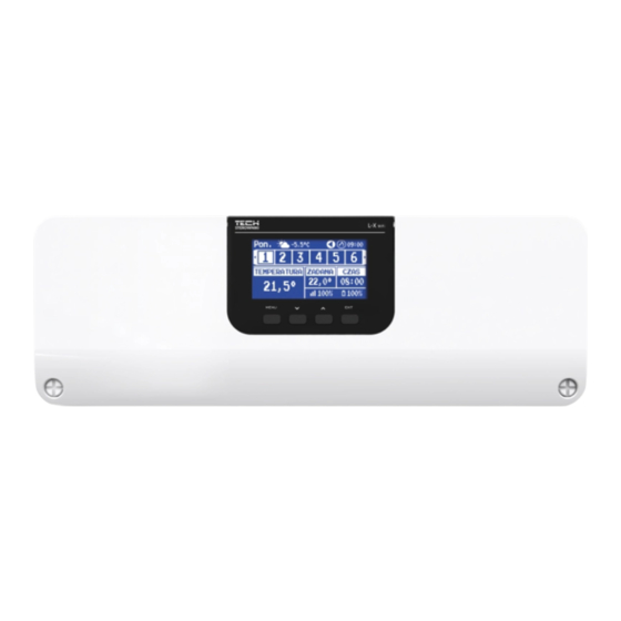
V. MAIN SCREEN DESCRIPTION The control is carried out by means of buttons located under the display. Controller display. 1. MENU button - enters the controller menu, confirming the settings. button - used to browse the menu functions or decrease the value of the edited parameters. This button also switches the operation parameters between the zones. - Page 11 5. Current time 6. Information about the operating mode/schedule in the respective zone local schedule constant temperature G-1….G-5 global schedule 1-5 02:08 time-limited 7. Signal strength and battery status of the room sensor information 8. Preset temperature in a given zone 9.
-
Page 12: Controller Functions
VI. CONTROLLER FUNCTIONS OPERATION MODE This function enables activation of the selected operating mode. ➢ Normal mode – the preset temperature depends on the set schedule ➢ Holiday mode – the set temperature depends on the settings of this mode Menu →... - Page 13 Schedule editing Menu → Zones → Zone… → Operating mode → Schedule… → Edit 1. Days on which the above settings apply 2. Temperature set outside the time intervals 3. Set temperatures for time intervals 4. Time intervals To configure a schedule: •...
-
Page 14: Controller Settings
CONTROLLER SETTINGS ➢ Time settings - the current time and date can be automatically downloaded from the network if the Internet module is connected and the automatic mode is enabled. It is also possible for the user to manually set the time and date if the automatic mode does not operate correctly. - Page 15 4.1.5. SETTINGS ➢ Weather control - the option to turn the weather control on/off. CAUTION Weather control works only if in the Menu → Fitter’s menu → External sensor, Weather control option was checked. ➢ Heating – the function enables/disables the heating function. There is also a selection of a schedule that will be valid for the zone during heating and for editing of a separate constant temperature.
- Page 16 4.1.6. ACTUATORS ➢ Settings • SIGMA - the function enables seamless control of the electric actuator. The user can set the minimum and maximum openings of the valve – this means that the degree of opening and closing of the valve will never exceed these values.
- Page 17 4.1.7. WINDOW SENSORS ➢ Settings • On - the function enables the activation of window sensors in a given zone (window sensor registration required). • Delay Time - This function allows you to set the delay time. After the preset delay time, the main controller responds to the opening of the window and blocks heating or cooling in the respective zone.
-
Page 18: Additional Contacts
➢ Operation mode • Off – Selecting this option disables the floor heating mode, i.e. Floor Protection Comfort Mode are not active. • Floor protection – This function is used to keep the floor temperature below the set maximum temperature to protect the system from overheating. -
Page 19: Mixing Valve
4.3. MIXING VALVE The EU-L-X WiFi controller can operate an additional valve using a valve module (e.g. i-1m). This valve has RS communication, but it is necessary to carry out the registration process, which will require you to quote the module number located in the rear of its housing, or in the software information screen). - Page 20 Example: Valve preset temperature: 50°C Hysteresis: 2°C Valve stop: 50°C Valve opening: 48°C Valve closing: 52°C When the set temperature is 50°C and the hysteresis is 2°C, the valve will stop in one position when the temperature reaches 50°C, when the temperature drops to 48°C, it will start to open and when it reaches 52°C, the valve will start to close in order to lower the temperature.
- Page 21 Heating curve - this is the curve according to which the set temperature of the controller is determined on the basis of the external temperature. In order for the valve to operate properly, the set temperature (downstream the valve) is set for four intermediate external temperatures: -20°C, -10°C, 0°C and 10°C. There is a separate heating curve for the Cooling mode.
- Page 22 ➢ Proportionality coefficient – The proportionality coefficient is used to determine the valve stroke. The closer to the set temperature, the smaller the stroke. If this coefficient is high, the valve will reach a similar opening faster, but it will be less precise. The percentage of the unit opening is calculated using the following formula: (set temperature –...
- Page 23 • Pump anti-stop - When enabled, the valve pump will turn on every 10 days for 2 minutes. This prevents water from fouling the installation outside the heating season. • Closing below temperature threshold - When this function is activated (check the Enabled option), the valve will remain closed until the boiler sensor reaches the pump switching temperature.
-
Page 24: Internet Module
MODE 2 - in this mode, it is possible to program the temperature deviations in detail for all working days (Monday – Friday) and for the weekend (Saturday – Sunday). To do this: → Select the option: Set Mode 2 →... -
Page 25: Manual Mode
CAUTION This function is only available when an external sensor has been registered in the EU-L-X WiFi controller. You can connect an external temperature sensor to the EU-L-X WiFi controller, which allows you to switch on the weather control, by: ➢... -
Page 26: Potential-Free Contact
4.9. PUMP The EU-L-X WiFi controller controls the operation of the pump – it turns on the pump (after counting down the delay time) when any of the zones is underheated and when the floor pump option is enabled in the respective zone. When all zones are heated (the set temperature is reached), the controller switches off the pump. -
Page 27: Factory Settings
➢ Bypass – an option needed in the absence of a buffer, providing the heat pump with an appropriate heat capacity. It relies on sequential opening of subsequent zones every specified time. • Floor pump – activate/deactivate floor pump • Cycle time –... - Page 28 - Inappropriate valve on the radiator - The valve got stuck ERROR #3 - Inappropriate valve on the - Inspect the valve operation radiator - Replace the valve on the radiator - Too little stroke (movement) of - Check the valve stroke the valve - No range ERROR #4...
-
Page 29: Software Update
VIII. SOFTWARE UPDATE To upload new software, disconnect the controller from the network. Insert the USB flash drive containing the new software into the USB port. Then connect the controller to the network while holding down the EXIT button. Hold down the EXIT button until you hear a single beep marking the start of new software uploading. - Page 30 EU DECLARATION OF CONFORMITY Hereby, we declare under our sole responsibility that EU-L-X WiFi manufactured by TECH STEROWNIKI, head‐quartered in Wieprz Biała Droga 31, 34‐122 Wieprz, is compliant with Directive 2014/53/EU of the European parliament and of the Council of 16 April 2014 on the harmonisation of the laws of the Member States relating to the making available on the market of radio equipment, Directive 2009/125/EC establishing a framework for the setting of ecodesign requirements for energy‐related products as well as the regulation...
Need help?
Do you have a question about the EU-L-X WiFi and is the answer not in the manual?
Questions and answers