Table of Contents
Advertisement
Quick Links
Advertisement
Table of Contents

Related Manuals for Miltenyi Biotec UltraMicroscope II

Summary of Contents for Miltenyi Biotec UltraMicroscope II
- Page 1 UltraMicroscope II Imaging System User manual...
- Page 2 UltraMicroscope II Imaging System may make copies solely for purposes of training personnel in the use and servicing of the unit within their business or organization. Maximal care has been taken by Miltenyi Biotec in the preparation of this user manual.
- Page 3 User manual Original instructions Issued: 2022-11 213443.01 Distributed by Manufactured by Miltenyi Biotec B.V. & Co. KG LaVision BioTec GmbH - a Miltenyi Biotec Company Friedrich-Ebert-Straße 68 Astastraße 14 51429 Bergisch Gladbach 33617 Bielefeld Germany Germany Phone +49 2204 8306-0...
- Page 4 Before using the UltraMicroscope II Imaging System, read the chapter Important safety information and all other information contained in this user manual, including any safety and operating instructions. Pay special attention to all warnings displayed on the instrument.
-
Page 5: Table Of Contents
Content 1 Important safety information 2 Introduction 2.1 The UltraMicroscope II Imaging System 2.2 Intended use 2.3 Instrument description 2.3.1 Front view Zoom Body configuration 2.3.2 Rear view Zoom Body configuration 2.3.3 Front view Super Plan configuration 2.3.4 Rear view Super Plan configuration 2.3.5 Detail view of electronic interface 3 Installation 3.1 Components Zoom Body configuration... - Page 6 6.3 Setting the light sheet path 6.4 Adjusting the lateral light sheets on the right-hand side 6.5 Adjusting the central light sheet on the left-hand side 6.6 Adjusting the lateral light sheets on the left-hand side 7 Setting up an experiment 7.1 Placing the sample 7.2 Capturing a single-color z-stack 7.2.1 Aligning the sample...
-
Page 7: Important Safety Information
• If it is necessary to cut the power supply, unplug the cable from the power outlet and contact an authorized Miltenyi Biotec service provider or Miltenyi Biotec Technical Support. • Check the instrument before each use for visible damage. • Do not use the instrument if it has been dropped or is damaged. Contact Miltenyi Biotec Technical Support immediately. - Page 8 Hazard levels Signal words are used to warn against hazardous situations and property damages. The following signal words are used in this user manual. or WARNING! indicates a hazardous situation that, if not avoided, could result in death or serious injury.
- Page 9 • Inspect the safety labels and safety markings regularly and replace them if they are not legible or identifiable from a safe viewing distance. • Contact Miltenyi Biotec for replacement labels. Figure 1.1: Hazard areas and safety symbols on the top side of the UltraMicroscope II Imaging System Electrical and thermal hazards ELECTRICAL HAZARD Electric shock, short circuit, overheating, fire, and explosion may lead to death or serious injury.
- Page 10 • Only use the power supply provided. If you have questions about the type of power source to use, contact the Miltenyi Biotec Technical Support or your local electricity supplier. Liquids inside the instrument Liquids inside the instrument can cause short circuits.
- Page 11 • If parts of the instrument are damaged, unplug and do not use the instrument until damaged parts are replaced. Contact Miltenyi Biotec Technical Support, if necessary. • Follow the instructions in the data sheet for each consumable.
- Page 12 Heavy instrument • Only use tables that support a weight of 250 kg. • Do not install the instrument yourself. • Only trained Miltenyi Biotec personnel or personnel authorized by Miltenyi Biotec is allowed to install the instrument. ERGONOMIC HAZARD Risk of tearing or straining muscles.
- Page 13 Transportation The instrument should be transported with care in packaging specified by Miltenyi Biotec. Internal damage can occur if the instrument is subjected to excessive vibration or if it is dropped. If the instrument needs to be shipped back to the manufacturer for service, contact Miltenyi Biotec for instructions and packaging materials.
-
Page 15: Introduction
The Super Plan Module can be mounted directly to the focusing unit of existing systems. The UltraMicroscope II Imaging System can be upgraded with an in vivo sample cuvette, which allows setting and maintaining of a constant immersion medium temperature and CO₂/O₂ atmosphere within the cuvette. -
Page 16: Instrument Description
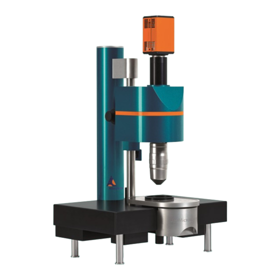
For the Super Plan configuration, there are two laser configurations and two camera configurations available. There are three different objectives and four dipping caps available. This guarantees a higher image quality. 2.3.1 Front view Zoom Body configuration Figure 2.1: Front view of the UltraMicroscope II Imaging System Zoom Body configuration Camera Objective lens Zoom knob... -
Page 17: Rear View Zoom Body Configuration
Figure 2.2: Rear view of the UltraMicroscope II Imaging System Zoom Body configuration Cable duct Type label Cable duct Electronic interface 2.3.3 Front view Super Plan configuration Figure 2.3: Front view of the UltraMicroscope II Imaging System Super Plan configuration with position numbers Camera Light sheet forming unit Focusing unit Power switch Objective lens Cover plate... -
Page 18: Rear View Super Plan Configuration
2.3.4 Rear view Super Plan configuration Figure 2.4: Rear view of the UltraMicroscope II Imaging System Super Plan configuration Cable duct Type label Controller connection I/O ports Cable duct... -
Page 19: Detail View Of Electronic Interface
2.3.5 Detail view of electronic interface Figure 2.5: Detail view of the I/O ports and power switch Power supply Camera trigger Jog wheel PC connection Detection unit Power switch Figure 2.6: Detail view of the coupling box Laser fibre (1) Optional: Laser fibre (2) -
Page 21: Installation
Installation Components Zoom Body configuration The Beam Combiner and the White Light Laser configuration are delivered with lasers, objective lenses, and emission filters, as specified when ordering the instrument. Additional accessories and consumables developed specifically for the system are available separately. Refer to Table 3.2 and Table 3.5. For details, visit www.miltenyibiotec.com or contact your local sales representative. -
Page 22: Accessories Zoom Body Configuration
150-000-527 Cuvette for UltraMicroscope II Imaging System 150-000-529 Table 3.2: Optional accessories available for the UltraMicroscope II Imaging System Components Super Plan configuration The Beam Combiner and the White Light Laser configuration are delivered with lasers, objective lenses, and emission filters, as specified when ordering the instrument. Additional accessories and consumables developed specifically for the system are available separately. -
Page 23: Accessories Super Plan Configuration
Alignment tool for UltraMicroscope II Imaging System 150-000-520 Sample holder set for UltraMicroscope II Imaging System 150-000-527 Cuvette for UltraMicroscope II Imaging System 150-001-731 Table 3.4: Optional accessories available for the UltraMicroscope II Imaging System Consumables Consumables Order no. MACS Clearing Kit 130-126-719... -
Page 24: Unpacking And Installation
Protect the instrument from shock and vibration. Do not place vibrating devices, such as vortex mixers, on the same table as the instrument. This could impair the quality of the results. Only Miltenyi Biotec service personnel is allowed to unpack and install the instrument. Contact Miltenyi Biotec Technical Support for further information. -
Page 25: Operation
Operation Switching on the instrument 1 Ensure that all components are connected to the power supply. 2 Switch on the external laser module. The key switch is located on the laser module, refer to manufacturer documentation. 3 Switch on the instrument. The power switch is located on the right-hand side of the instrument, refer to Instrument description on page 14. - Page 26 Name Function Location Rayleigh ROI Switches on the light sheet focus in Live window the live window Show crosshair Switches on the crosshair in the live Live window window Select left light sheet Activates the light sheet on the left- Settings 1 window hand side Select both light sheets...
-
Page 27: Preparing The Instrument
Preparing the instrument Preparing the instrument BIOLOGICAL HAZARD Contamination or infection may lead to death or serious injury depending on the material used. • Take care when handling samples and reagents. • Immediately replace the waste bottle after unmounting and fasten the bottle closure to the new bottle. •... -
Page 28: Setting The Parameters For The Alignment
3 Fill the cuvette up to the notch (2) on the side with the selected imaging solution. 4 Place the cuvette securely on its holders again by holding the piston. NOTICE! Be careful not to spill any imaging solution. 5 Lower the piston carefully until the bottom of the microscope chamber is reached. 6 Fasten the cover plate by tightening the screw. - Page 29 5 Set Optics > sheet NA to the maximum. 6 Set Optics > sheet width to 20%. 7 Select the Measurement tab, and select the imaging solution used in the cuvette under Liquid. 8 Set the exposure time to a value between 100 and 200 ms in the Camera view. 9 Select the objective lens, such as Olympus 2×...
-
Page 31: Laser Alignment
Laser alignment Light sheet alignment To generate high-contrast images with the best z-resolutions, all light sheets must be perfectly aligned to the same z-plane. A set of adjustable precision screws on the left-hand and the right-hand side of the instrument can be used to align the individual beams creating the light sheet. -
Page 32: Placing The Alignment Tool
Placing the alignment tool 1 Attach the alignment tool with the sample holder to the sample holder frame. 2 Place the sample holder frame into the cuvette. Setting the light sheet path LASER RADIATION Direct exposure to laser beam may lead to eye injury. •... - Page 33 4 Check by eye that the alignment tool is in a centered position, and move it into the light sheets by using the jog wheel. The light sheets from the right-hand side should pass the pinhole and form thin lines on the other side.
- Page 34 9 Select the Advanced tab. Always start with the central light sheet on the right-hand side. It is the reference light sheet that cannot be adjusted by the user. Click Laser beam adjustment > Right > 1 to activate the central beam.
- Page 35 If it is not possible to align the light sheet by lowering or raising the alignment tool, the actual position of the horizontal focus does not match with the position displayed in the ImSpector software. Align the central light sheet as well as possible before adjusting the horizontal focus. Adjusting the horizontal focus 1 Select the Advanced tab on the bottom of the Settings 1 window.
-
Page 36: Adjusting The Lateral Light Sheets On The Right-Hand Side
After the settings have been saved, the alignment tool must not be moved again. It is highly recommended to block the third button from the left of the jog wheel. Adjusting the lateral light sheets on the right-hand side To adjust the lateral light sheets on the right-hand side, the horizontal focus must not be changed. 1 Click Laser beam adjustment >... -
Page 37: Adjusting The Lateral Light Sheets On The Left-Hand Side
4 Align the central light sheet of the left side to the pinhole by using the adjustment screw Z1 on the left- hand side. 5 Move the slider Sheetmotor Calibration in the Settings 1 window until only one light sheet passes the pinhole. -
Page 39: Setting Up An Experiment
Setting up an experiment Placing the sample 1 Fix the sample to the sample holder of the sample holder frame. 2 Attach the sample holder to the sample holder frame. 3 Place the sample holder frame into the cuvette. NOTICE! Ensure not to drop any medium into the microscope chamber. Capturing a single-color z-stack 7.2.1 Aligning the sample... - Page 40 3 Select Measurement Mode > Acquisition for measuring a z-stack. 4 Select xyz-Table Z in the Devices list. 5 Click the Autosave button at the end of the row under AS. It will turn green. 6 Click the Autosave Settings button to select the storage location. 7 Select the Measurement tab in the Settings 1 window, and select the imaging solution used in the cuvette.
-
Page 41: Optimizing The Measurement Settings
11 Click the Start live preview button in the Measurement Wizard window to start the live preview. 12 Lower the objective lens. 13 Click the Show crosshair button on the right side of the live window to activate the crosshair. 14 Use the jog wheel to move the sample inside the cuvette until the surface of the sample is visible in the center of the crosshair. -
Page 42: Capturing An Image
5 Optional: Move the slider under Optics > sheet width to change the sheet width of the light sheet. A lower sheet width will result in more light being focused on a smaller region of the sample. The field of view needs to be adjusted. -
Page 43: Capturing A Multi-Color Z-Stack
Capturing a multi-color z-stack 1 Select Measurement Mode > Multi Color Acquisition in the Measurement Wizard window. 2 Select xyz-Table Z and UltraII Filter in the Devices list. 3 Click the Autosave button at the end of the row under AS. It will turn green. 4 Select the correct excitation and emission wavelengths for your sample under Filter for Measurement in the Settings 1 window. -
Page 44: Capturing A Mosaic Image
Capturing a mosaic image 1 Select Measurement Mode > Mosaic Acquisition in the Measurement Wizard. 2 Click the Mosaic tab in the xyz-Table Visual XY window. 3 Double-click the green square representing the field of view. The square will turn gray. 4 Click and drag the black dots at the edges to create a mosaic. - Page 45 5 Enter a percentage value to set an Overlap. 6 To start the measurement, proceed as described under Capturing an image on page 40...
-
Page 47: Maintenance
Maintenance Servicing Service the instrument every 12 months. Contact Miltenyi Biotec for support. Cleaning the instrument Use only small amounts of suitable cleaning agents on a soft cloth to wipe the instrument. 1 Unplug the instrument. 2 To disinfect, wipe accessible surfaces with 70% ethanol or isopropanol. -
Page 49: Technical Data And Specifications
Technical data and specifications Specifications The safety of the instrument may be compromised if used outside its specifications. UltraMicroscope II Imaging System specifications General information Zoom Body configuration Super Plan configuration Dimensions (w × d × h) 54 cm × 82 cm × 65 cm 54 cm ×... - Page 50 Thickness 4–24 μm Width 1–20 mm Numerical aperture 0.0135–0.135 Focus positioning Dynamic Table 9.1: UltraMicroscope II Imaging System specifications Camera specifications Detector 4.2 MP sCMOS camera 5.5 MP sCMOS camera Active pixels (w × h) 2048 × 2048 2560 × 2160 Pixel size 6.5 μm ×...
-
Page 51: Eu Declaration Of Conformity
EU Declaration of Conformity This declaration of conformity is issued under the sole responsibility of the manufacturer: LaVision BioTec GmbH - a Miltenyi Biotec Company Astastraße 14 33617 Bielefeld Germany Description: Laboratory equipment Product name: UltraMicroscope II We hereby declare that the product conforms to the requirements of the following directives:... -
Page 52: Uk Declaration Of Conformity
UK Declaration of Conformity This declaration of conformity is issued under the sole responsibility of the manufacturer: LaVision BioTec GmbH - a Miltenyi Biotec Company Astastraße 14 33617 Bielefeld Germany Description: Laboratory equipment Product name: UltraMicroscope II We hereby declare that the product conforms to the requirements of the following directives:... -
Page 53: Technical Support
Technical support For technical support, contact your local Miltenyi Biotec representative or Miltenyi Biotec Technical Support at Miltenyi Biotec headquarters: Miltenyi Biotec B.V. & Co. KG Friedrich-Ebert-Straße 68 51429 Bergisch Gladbach Germany Phone: +49 2204 8306 3803 technicalsupport@miltenyi.com Visit www.miltenyibiotec.com for local Miltenyi Biotec Technical Support contact information. -
Page 55: Legal Notes
Miltenyi Biotec group which supplied the product in effect at the date of purchase. Those terms and conditions of sale may vary by country and region. Nothing in this document should be construed as constituting an additional warranty. -
Page 56: Trademarks
Miltenyi Biotec’s warranty does not cover products sold AS IS or WITH ALL FAULTS, or which had its serial number defaced, altered, or removed, or any consumables or parts identified as being supplied by a third party. Miltenyi Biotec must be informed promptly if a claim is made under this limited warranty. If a material or... - Page 58 Miltenyi Biotec provides products and services worldwide. Visit www.miltenyibiotec.com/local to find your nearest Miltenyi Biotec contact. Unless otherwise specifically indicated, Miltenyi Biotec products and services are for research use only and not for therapeutic or diagnostic use. MACS and the Miltenyi Biotec logo are either registered trademarks or trademarks of Miltenyi Biotec and/or its affiliates in various countries worldwide.
Need help?
Do you have a question about the UltraMicroscope II and is the answer not in the manual?
Questions and answers