Table of Contents
Advertisement
Quick Links
Advertisement
Table of Contents
Troubleshooting

Related Manuals for IMO i3N Series


Summary of Contents for IMO i3N Series
- Page 1 User Manual For i N Series Controllers Think inside the box...
-
Page 2: Preface
PREFACE This manual explains how to use the I3N Controller. Copyright© IMO Precision Controls Ltd all rights reserved. No part of this publication may be reproduced, transmitted, transcribed, stored in a retrieval system, or translated into any language or computer language, in any form by any means, electronic, mechanical, magnetic, optical, chemical, manual or otherwise, without the prior agreement and written permission of IMO Precision Controls Ltd. -
Page 3: Limited Warranty And Limitation Of Liability
LIMITED WARRANTY AND LIMITATION OF LIABILITY IMO, warrants to the original purchaser that the I3N controller module manufactured by IMO is free from defects in material and workmanship under normal use and service. The obligation of IMO under this warranty shall be limited to the repair or exchange of any part or parts which may prove defective under... -
Page 4: Table Of Contents
I3N100/08D12-SEHF Power Wiring ..................19 Register Definitions ........................20 Useful %S and %SR registers ..................... 21 Resource Limits ......................... 29 Register Map for I3N Series ...................... 30 CHAPTER 6: i3 CONFIGURATOR CONFIGURATION ................31 Overview ........................... 31 I3 configurator Status Bar ......................31 Establishing Communications .................... - Page 5 Battery Life ..........................49 Lithium Battery Safety ......................49 Battery Charging Status ......................50 Battery Charging State ......................50 Battery Status in System Registers ................... 50 Overview ........................... 51 MJ1 Serial Port Pinout ......................51 i3 configurator Programming via Serial Port ................53 Ladder-Controlled Serial Communication ................
- Page 6 15.1 Firmware Updates ......................... 83 15.2 Backup Battery ........................83 CHAPTER 16: MODBUS COMMUNICATIONS ..................84 16.1 Modbus Overview ......................... 84 16.2 Modbus Slave Overview ......................84 16.3 Modbus Master Overview ..................... 85 16.4 Modbus Addressing Table for I3N Units ................86 CHAPTER 17: TROUBLESHOOTING / TECHNICAL SUPPORT ..............
-
Page 7: Safety Warnings And Guidelines
CHAPTER 1: SAFETY / COMPLIANCE Safety Warnings and Guidelines When found on the product, the following symbols specify: Warning – Consult user documentation. Warning – Electrical Shock Hazard. WARNING – EXPLOSION HAZARD – Do not disconnect equipment unless power has been switched off or the area is known to be non-hazardous. -
Page 8: Grounding
Before each use, inspect all cables for breaks or cracks in the insulation. Replace immediately if defective Grounding Grounding is covered in various chapters within this manual. Compliance To check for compliance and updates, visit the IMO website. IMO: https://imopc.com... -
Page 9: Chapter 2: Introduction
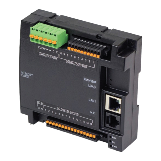
CHAPTER 2: INTRODUCTION General Overview of a I3N100/14004-SEHF & I3N100/08D12-SEHF I3N I/O Connectors Recessed Buttons -Run/Stop -Load RJ-45 Ports LED Lights -Run -PWR I/O Connectors Figure 02.1 – Overview of the I3N... - Page 10 2.2.1 Where to Find Information about the I3N a) Datasheet - The datasheet is the first document to refer to for key information related to specific I3N models. The datasheets are available on the IMO website and contain pin-outs and other model specific information.
-
Page 11: Connectivity To The I3N
Connectivity to the I3N The I3N has excellent capabilities for connecting to a variety of devices. The diagram below shows some examples of devices that can be used with the I3N. Other Control Other i3 Devices Devices Smart I/O Serial Drives PLCs Bar Code Readers... -
Page 12: Features Of I3N
Features of I3N The I3N are industrial control devices with built in I/O. They combine control, I/O, and networking into a single, integrated package. Unique features of the I3N include: Advanced control capabilities including floating point, multiple auto tuning PID loops, and string handling capabilities Removable media for storage of programs, data logging, and on-site updating iCAN networking for communication with remote I/O, other controllers, or PCs... -
Page 13: Useful Documents And References
Useful Documents and References Visit our website to obtain user documentation, supplemental documents, certificates, and other documentation. IMO: https://imopc.com Opening I3 configurator Help File After opening the i3 configurator Help file, either use the Contest, Index or Search tabs to located information. -
Page 14: Chapter 3: Mechanical Installation
NOTE: The datasheet is the first document to refer to for information related to I3N models such as pin- outs, I/O and general specification, and other key installation information. Visit the IMO websites to obtain datasheets, user documentation, and updates. -
Page 15: I3N Installation
I3N Installation These I3N modules are suitable for use in the Class I, Division 2, Groups A, B, C and D Hazardous Locations only. The operating temperature range is -10˚C to +60˚C. WARNING - EXPLOSION HAZARD - DO NOT DISCONNECT EQUIPMENT UNLESS POWER HAS BEEN SWITCHED OFF OR THE AREA IS KNOWN TO BE NON-HAZRDOUS. - Page 16 3.3.1 Temperature / Ventilation Ensure that the DIN Rail layout design allows for adequate ventilation and maintains the specified ambient temperature range. Consider the impact on the design if operating at the extreme ends of the ambient temperature range. For example, if it is determined that a cooling device is required, allow adequate space and clearances for the device in the panel box or on the panel door if DIN rail is mounted inside.
-
Page 17: Chapter 4: Electrical Installation
Ideally, a ground resistance measurement from equipment to earth ground is 0Ω. In reality, it typically is higher. The U.S. National Electrical Code (NEC) states the resistance to ground shall not exceed 25Ω. IMO recommends less than 15Ω resistance from our equipment to ground. Resistance greater than 25Ω can... -
Page 18: How To Test For Good Ground
How to Test for Good Ground In order to test ground resistance, a Ground Resistance Tester must be used. A typical Ground Resistance Meter Kit contains a meter, two or three wire leads, and two ground rods. Instructions are supplied for either a two-point or three-point ground test. -
Page 19: I3N100/14004-Sehf Power Wiring
I3N100/14004-SEHF Power Wiring To power up the I3N100/14004-SEHF, supply 10-30VDC to the V1+ and V- connections on the Power & Input connector. See image below. OPTION: Attach ferrite core with a minimum of two turns of the DC+ and DC- signals from the DC supply that is powering the controllers. -
Page 20: Register Definitions
CHAPTER 5: REGISTERS Register Definitions When programming the I3N, data is stored in memory that is segmented into different types. This memory in the controller is referred to as registers. Different groups of registers are defined as either bits or words (16 bits). -
Page 21: Useful %S And %Sr Registers
Useful %S and %SR registers For additional information on system bits and registers, refer to the i3 configurator Help file. Table 5.2– Common %S Register Definitions Register Description Indicate First Scan Network is OK 10mS timebase 100mS timebase 1 second timebase I/O is OK Always ON Always OFF... - Page 22 Table 5.3 – %SR Registers – Master %SR Table Default Min-Max Program Display Register Description Name Values (Read/Write) (Read/Write) 24= License Details *Excludes I3N Units. %SR4 SELF_TST Self-Test Results Read Only Read Only %SR4.1 Self-Test Results – BIOS Error Read Only Read Only %SR4.2 Self-Test Results –...
- Page 23 Table 5.3 – %SR Registers – Master %SR Table Default Min-Max Program Display Register Description Name Values (Read/Write) (Read/Write) CANOpen Mode 1 to 127 Network Baud Rate 0=125KB 1= 250kB 0 to 4 %SR30 Read Only Read/Write 2= 5000KB 3= 1MB 4=50K Network Required 0= Network not required...
- Page 24 Table 5.3 – %SR Registers – Master %SR Table Default Min-Max Program Display Register Description Name Values (Read/Write) (Read/Write) %SR52 Watchdog-Tripped Error Count Read Only Read Only %SR53-54 Reserved %SR55.13 Self-Test: Battery Low or Missing Read Only Read Only Key Currently Pressed No key = 0 (No key pressed since power- F1 = 1 F2= 2...
- Page 25 Table 5.3 – %SR Registers – Master %SR Table Default Min-Max Program Display Register Description Name Values (Read/Write) (Read/Write) *Excludes I3N Units USER_LEDS %SR58 User LEDs Read/Write Read/Write Engine Build Number (Only last three %SR59 Read Only Read Only numbers displayed) Build Option Build Test = 0 0 to 2...
- Page 26 Table 5.3 – %SR Registers – Master %SR Table Default Min-Max Program Display Register Description Name Values (Read/Write) (Read/Write) MJ1 Termination Enable %SR152.3* Read / Write Read / Write *i3AX/BX, I3N2414 Only MJ1 Biasing *i3HX %SR152.4* Read / Write Read / Write CAN Termination Enable *i3CL &...
- Page 27 Table 5.3 – %SR Registers – Master %SR Table Default Min-Max Program Display Register Description Name Values (Read/Write) (Read/Write) %SR172 Y-Coordinate Touched Read Only Read Only %SR173 System-Function Disable, 0 to 1 Read / Write Read / Write %SR174 Removable Media Protect Read/Write Read/Write %SR174.1...
- Page 28 Table 5.3 – %SR Registers – Master %SR Table Default Min-Max Program Display Register Description Name Values (Read/Write) (Read/Write) *i3HX – Frequency in MHz Battery Charge Temp High %SR195 Read Only Read Only *i3HX – in degree centigrade Charging State 0=Waiting 1=Normal Charging 2=Hot Charge...
-
Page 29: Resource Limits
Table 5.3 – %SR Registers – Master %SR Table Default Min-Max Program Display Register Description Name Values (Read/Write) (Read/Write) Expiration Date of I3RMI License, license detail. %SR220-222 Read Only Read Only (i3AX/BX, i3CL, & i3EL use %SR101 & %SR108-112 for I3RMI License Details) Resource Limits Table 5.4 –... -
Page 30: Register Map For I3N Series
Register Map for I3N Series Table 5.5—I3N Series Register Map I3N Model REGISTER DESCRIPTION TYPE %I1 to %I14 Digital Inputs I3N100/14004- %I15 Reserved SEHF %I16 %Q Fault Status %Q1 to %Q10 Digital Outputs %I1 to %I8 Digital Inputs %I9 to %I15... -
Page 31: Chapter 6: I3 Configurator Configuration
CHAPTER 6: i3 CONFIGURATOR CONFIGURATION Overview I3N hardware is programmed with a Windows based PC application called i3 configurator. This application can be used to program, configure, monitor, and debug all aspects of the I3N unit. Please see the online help provided with i3 configurator for additional details. -
Page 32: Establishing Communications
Establishing Communications The I3N can communicate with i3 configurator using serial port communications via MJ1 Port, Ethernet, and CAN (iCAN). For I3N, use i3 configurator Version 9.90 SP5 or later. Connect a PC (Personal Computer running a Windows Microsoft operating system) serial port to the MJ1 port on the I3N. - Page 33 The PC will detect a new device has been plugged into the USB port. Now that the I3N is plugged in, go to i3 configurator Controller Connection Wizard. If you are just opening i3 configurator, Connection Wizard usually opens by default. Select USB and click Next >>.
- Page 34 If the Connection Wizard does not pop up upon opening I3 configurator, then select Controller (in the i3 configurator tool bar) Connection Wizard, choose your connection method. If you are connecting for the first time, we suggest connecting via USB. Figure 6.3 –...
- Page 35 An alternate way to select the COM setting is to go to i3 configurator Tools Application Settings Communication choose port. Figure 6.4 – i3 configurator: Alternative Connection Method Screenshot Figure 6.5 – Add Target Screenshot in the i3 configurator NOTE: The following fields, Target Name, Connection Medium, Connected Device, and Connection Settings, need to be filled for communication configuration if i3 configurator Connection Wizard was not used.
- Page 36 Select this option to communicate over Ethernet. Provide the IP address of the device and select the mode: Built in/ ETN Ethernet mode. Select i3 M GPRS mode if communication with I3N series controller on GPRS is required and the device has GSM modem installed in I3N series controller.
- Page 37 If communication is established, the target indicator will show the mode of the controller Target: yy(R) as shown in the status section above in this chapter, section I3 configurator Status Bar. If the controller is not communicating, ensure the target ID is set correctly. The Target ID allows directing communications to a particular unit when multiple units are connected via an iCAN network.
- Page 38 11.3.2 Communicating via On Board Ethernet Port From the factory, the I3N i3 is set to the IP Address 192.168.254.128. To obtain Ethernet communications between I3 configurator and the I3N I3 using a single Ethernet cable between a PC and the I3N, or through an unmanaged Ethernet Switch, the PC will also need to be manually configured as follows (may require Administrator access on PC): 1.
- Page 40 To configure the Ethernet settings of the I3N using i3 configurator, go to Controller Hardware Configuration. If not already done, select the correct connected controller, or use the Auto Config button to automatically recognize a controller that is already successfully connected to I3 configurator. Below the main controller configuration, under Network Ports, find LAN1 and click on the Config button to the right of the greyed-out ETN300.
-
Page 41: Hardware Configuration
System button to automatically detect the connected I3N model. 3. If the I3N is not connected: a. Select I3N Series from the Series dropdown. b. Confirm the I3N module in the Device Type dropdown. c. Select the model to be used from the Model # dropdown. - Page 42 Click the Local I/O tab to access the configuration for the I/O. From here, the I/O map and addresses may be viewed. These addresses may not be changed and no other program configurations, such as remote I/O, should overlap these addresses. 6.
- Page 43 8. Configure the Digital Outputs to be in the desired state when the I3N is put into STOP mode, such as when a program is being loaded. a. By default, outputs will turn ‘OFF’. b. Outputs may be set to turn ‘ON’. c.
-
Page 44: Scaling Analog Inputs
Scaling Analog Inputs To access the Advanced Math Scaling function, select Tools Project Toolbox. This will open a side bar, and then select Advanced Math Scale. - Page 45 Example 1: The i3 configurator Scale function, found in the Advanced Math functions, allows for very easy conversion of the raw input value into a meaningful reading. For example, a pressure transducer may be specified as a 4-20mA signal to signify a 0-2000 psi pressure reading. With the analog channel set to the 4.20mA range, the raw analog input value, which is in INT format ranges from 0 to 4mA to 32000 for 20mA.
-
Page 46: Chapter 7: General I/O
NOTE: Each I3N unit is sent with a datasheet in the box. The datasheet is the first document to refer to for model-specific information related to I3N models for key installation information. Visit the IMO websites to obtain datasheets, user documentation, and updates. -
Page 47: Digital Inputs
Digital Inputs NOTE: The digital inputs on the I3N are designed for low-voltage DC inputs. The inputs are designed to support both positive and negative input modes. The mode is set by a configuration parameter in I3 configurator. All the inputs on the unit must be configured to the same mode. Positive Logic vs. -
Page 48: Analog Inputs
Analog Inputs The analog inputs on certain I3N models allow voltage or current measurement from a variety of devices. Analog inputs may read 0-20 mA current only or may also read 0-10VDC. Refer to the datasheet specific to the I3N model being used. The analog inputs have a digital filter that can be used to filter electrical noise that may be unavoidable in some installations. -
Page 49: Chapter 8: Back-Up Battery
The battery is UL recognized and comes from quality suppliers. The i3 has safety circuitry built into the charging IC and additional external protection including fusing. These circuits were closely evaluated by UL and IMO engineering for use in hazardous environments. -
Page 50: Battery Charging Status
Battery Charging Status Viewed in the System Menu under “View Battery Status” Waiting The charging system is waiting for voltages and temperatures to stabilize. Battery Charging The battery is charging. Battery Full Shows at the end of a charge cycle. Remains in this state until the battery is steadily discharging. -
Page 51: Overview
CHAPTER 9: SERIAL COMMUNICATIONS Overview All I3N models provide at least one serial port. On all models, the 8-pin modular connector labeled MJ1 is for serial communications and contains a RS232 port (MJ1). On I3N100/14004-SEHF and I3N100/08D12- SEHF models, the same connector also contains a 2-wire RS485 port (MJ2). By default, MJ1 can be connected to the COM port of a PC running i3 configurator, for controller programming. - Page 52 9.2.2 I3N100/08D12-SEHF MJ1 and MJ2 Pins MJ1: RS-232 w/full handshaking / MJ2: RS-485 half-duplex. I3N100/08D12-SEHF: MJ1 and MJ2 Pins MJ1 Pins MJ2 Pins Signal Direction Signal Direction Ground Ground +5V (60mA Max) +5V (60mA Max) RX- / TX- IN / OUT RX+ / TX+ IN / OUT...
-
Page 53: I3 Configurator Programming Via Serial Port
i3 configurator Programming via Serial Port The MJ1 serial port supports iCAN Programming Protocol. If a PC COM port is connected to the MJ1 serial port, i3 configurator can access the I3N for programming and monitoring. Programming can also be done via the CAN connection or Ethernet. -
Page 54: Chapter 10: Can Communications
CHAPTER 10: CAN COMMUNICATIONS NOTE: For additional CAN information, refer to the CAN Networks manual on the IMO website. 10.1 Overview All I3N models provide CAN networking options, which are implemented with CL and CH connections at the terminal. They are like the module shown below. The CAN connection is terminated (120Ω resistor) at each end of the network wiring for proper functionality. -
Page 55: Can Port Wiring
10.3 CAN Port Wiring The CN L and CN H communication wires must be terminated with a 120 Ω resistor. 10.3.1 I3N100/14004-SEHF CAN Port Wiring CAN communications are provided via three connectors on the CAN connector: CAN_LOW (CL), CAN_HIGH (CH), and V- (C). If iCAN expansion I/O is to be used, a 24VDC power source will be required on the iCAN bus in order to power the expansion I/O modules. - Page 56 10.3.2 I3N100/08D12-SEHF CAN Port Wiring Figure 10.5 – I3N100/08D12-SEHF CAN Port Wiring The CAN port is provided via three connections on the CAN, Power, and Analog connector: CAN_LOW (CL), CAN_HIGH (CH), and V- (C). If iCAN expansion I/O is to be used, a 24VDC power source will be required on the iCAN bus in order to power the expansion I/O modules.
-
Page 57: I3 Configurator Programming Via Can
10.4 i3 configurator Programming via CAN The CAN port supports iCAN Programming Protocol. If a PC has a CAN interface installed (via PCI card or USB), and the PC CAN port is connected to the I3N CAN port, i3 configurator can access the I3N for programming and monitoring. -
Page 58: Chapter 11: Ethernet Communication
11.2 MAC Address MAC Address: The I3N MAC Address is found in System Registers %SR35-36. All IMO controllers hold 00-E0 in the first two segments. Therefore, the first two segments of the MAC Address are not represented in System Registers. -
Page 59: Ethernet Module Protocols And Features
Ethernet Global Data SRTP Slave (90-30 Service Service Request Transfer Protocol Request) ICAN TCP Server IMO iCAN over Ethernet (for I3 configurator to I3 programming) Modbus Slave Modbus over Ethernet Ethernet / IP ODVA CIP over Ethernet FTP (File Server) -
Page 60: Ethernet Module Configuration
11.6 Ethernet Module Configuration NOTE: The following configuration is required for all applications regardless of the protocols used. Additional configuration procedures must be performed for each protocol used. To configure the Ethernet Module, use i3 configurator Programming Software to perform the following steps: On the main i3 configurator screen, select the Controller menu and its Hardware Configure sub-menu to open the Hardware Configuration dialog (Figure 11.1). - Page 61 Click the Config button to the right of LAN1 revealing the Ethernet Module Configuration dialog as shown in Figure 11.2. Figure 11.2 – Ethernet Module Configuration Configure the Ethernet Module parameters as follows: IP Address: Enter the static IP Address for the Ethernet Module being configured. NOTE: IP Addresses are entered as four numbers, each ranging from 0 to 255.
- Page 62 Table 11.3 - Ethernet Status Word Register Format High Byte Low Byte Dup Spd Link TCP Connections Status Values Status Bit(s) Status Indication Minimum Maximum Reserved Always 0 Link Duplex (Auto-Negotiated) 0 = Half Duplex 1 = Full Duplex Link Speed (Auto-Negotiated) 0 = 10MHz 1 = 100MHz Receive State...
-
Page 63: Ethernet Configuration - Ip Parameters
11.7 Ethernet Configuration – IP Parameters For primary operation, the IP address, Net Mask, and Gateway should be set in the LAN config of the i3 configurator Hardware Configuration. There are options to get IP parameters from the LAN Config or to get parameters from registers. -
Page 64: Chapter 12: Downloadable Communication Protocols
CHAPTER 12: DOWNLOADABLE COMMUNICATION PROTOCOLS 12.1 Overview Through loadable protocol device drivers, certain models of the i3 family can provide the ability to exchange data with remote devices such as variable-frequency drives, PLCs, and remote I/O devices. This feature greatly expands the i3 ’s control capability with negligible effect on the i3 ’s ladder scan time. Remote devices that communicate serially must do so under certain rules of data transfer known as a protocol. - Page 65 Each entry can be configured for one of two types of initiating a transaction: Polled and Triggered. Polled type entries initiate a transaction with the remote device on every transaction scan. Triggered type entries only initiate a transaction when a corresponding local (i3) binary trigger register is set. Once a triggered type of transaction completes, the protocol device driver resets the local (i3) binary register to indicate completion.
-
Page 66: Protocol Config
12.2 Protocol Config After opening i3 configurator, choose Program Protocol Config, and select the port drop-down box to select a protocol device driver. All protocol device drivers currently loaded in i3 configurator are displayed in the dropdown selection. Some i3 models can be limited in the number of ports or number of protocol device drivers that can be selected. -
Page 67: Network Configuration
11.3 Network Configuration Network Configuration provides the required parameters to configure the network. Each protocol is different and may not require all the Network Config field. Please refer to the table below for the options in the Network Config field. - Page 68 Table 11.1 – Network Protocols Baud Rate, Data Bits, Stop Bits, These field define the bit level transfer over the serial port. Parity None – No handshake lines are used Handshake Multidrop Full – Rx remains active while Tx is occurring. Multidrop Half –...
-
Page 69: Device List And Device Configuration
12.4 Device List and Device Configuration Device List The Device List is reached from the Device button on the Protocol Config screen and provides a list of the configured devices on the Network. Devices must be created and exist in this list before corresponding Scan List entries can be created for this device. - Page 70 Device Configuration This configuration is reached from the Device List when adding or modifying an existing device.
-
Page 71: Scan List
12.5 Scan List This can be accessed from the Scan List button on the Protocol Config screen or the Mapping button on the Device List screen and provides a Scan List of the Data Mapping entries. To transfer data between the I3 and remote target, a Scan List must be created that defines each transaction. -
Page 72: Data Mapping Configuration (Scan List Entry)
12.6 Data Mapping Configuration (Scan List Entry) Update Type This field specifies the direction and what triggers the transfer of data between the i3 and target device for a mapping entry. Polled Read On every transaction scan, a read-only target device register(s) transaction occurs. Polled Read/Write On every transaction scan, a read target device register transaction occurs unless a local register value has changed. - Page 73 Polled Read/Write/Init On every transaction scan, a read target device register transaction occurs unless a local register value has changed. The write transaction only updates those local registers that have changed in value. If several non-consecutive local registers (contained in a single mapping entry) change value between transaction scans, it takes several consecutive scans to write each changed register.
-
Page 74: Chapter 13: Removable Media
CHAPTER 13: REMOVABLE MEDIA 13.1 Overview All I3N models provide a Removable Media slot, labeled Memory Card, which supports standard microSD flash memory cards. microSD cards can be used to save and load applications, to capture graphics screens and to log data for later retrieval. Figure 13.1 –... -
Page 75: Using Removable Media To Log Data
13.4 Using Removable Media to Log Data Using Read and Write Removable Media function blocks, an application ladder program can read and write I3N register data in the form of comma-delimited files, with a .CSV extension. These files are compatible with standard database and spreadsheet PC programs. In addition, an application ladder program can use Rename and Delete Removable Media function blocks to rename and delete files. -
Page 76: Filenames Used With The Removable Media (Rm) Function Blocks
13.7 Filenames used with the Removable Media (RM) Function Blocks The RM function blocks support the flash with a DOS/Windows standard FAT-16 file system. All names must be limited to the “8.3” format where the filename contains eight characters a period then a three- character extension. -
Page 77: System Registers Used With Rm
13.8 System Registers used with RM Table 13.3 – RM System Registers %SR174 Removable Write a 1 to prohibit read/write access to the removable media card. Media Protect Write a zero (0) to allow access. %SR175 Status This shows the current status of the RM interface. %SR176 Free Space This 32-bit register shows the free space on the RM card in bytes. -
Page 78: Chapter 14: Fail-Safe System
CHAPTER 14: FAIL-SAFE SYSTEM 14.1 Overview The Fail-Safe System is a set of features that allow an application to continue running in the event of certain types of "soft" failures. These "soft" failures include: Battery power loss • Battery-Backed Register RAM or Application flash corruption due to, for example, an excessive •... -
Page 79: Backup / Restore Data
14.3 Backup / Restore Data Backup I3 Data: When initiated, this will allow the user to manually copy battery-backed RAM contents on to the onboard flash memory of the i3. This will have the effect of backing up all the registers and controller settings (Network ID, etc.) that would otherwise be lost due to a battery failure. - Page 80 The i3 follows the following sequence in execution of Automatic Restore: Figure 14.1 – Flow Chart for Automatic Restore...
-
Page 81: Autoload
14.4 Autoload This option allows the user to specify whether the i3 automatically loads the application AUTOLOAD.PGM located in Removable Media. When the Autoload setting is enabled (set to YES), it can be automatically initiated at power-up. The automatic initiation will happen only in the following two cases: •... -
Page 82: Autorun
The i3 follows the following sequence in execution of Autoload: Figure 14.2 – Flow Chart for Autoload 14.5 Autorun This option, when enabled (YES), allows the user to automatically place the I3 into RUN mode after the Autoload operation or automatic Restore Data operation. When the Autorun setting is disabled (NO), the I3 remains in the IDLE mode after a Restore Data or Autoload operation. -
Page 83: Chapter 15: Maintenance
NOTE: The battery is adhered to the unit and not replaceable. If the battery fails, please contact IMO Technical Support for further instructions. Do not attempt to disassemble the unit as the lithium battery may explode or catch fire if mishandled. -
Page 84: Chapter 16: Modbus Communications
CHAPTER 16: MODBUS COMMUNICATIONS 16.1 Modbus Overview For complete Modbus instructions, please refer to the Help file in I3 configurator. Modbus (serial) and Modbus TCP/Modbus UDP (Ethernet) are popular, de-facto standard protocols that allow industrial devices from multiple manufacturers to easily share data in real-time. For Modbus serial communications, the I3N can act as either a Master or a Slave. -
Page 85: Modbus Master Overview
Modbus addressing style for each slave on the network, a minimum of address conversion is required. Also, if the slave is another IMO product (i.e. another I3N or an i3), the “Native Addressing” option can be selected (i.e. %R1, %M17, etc.), and this skips the conversion to Modbus style altogether. -
Page 86: Modbus Addressing Table For I3N Units
16.4 Modbus Addressing Table for I3N Units To access I3N registers, a Modbus Master must be configured with the appropriate register type and offset. This is usually accomplished with one of two methods: 1. The first method uses Traditional Modbus References, in which the high digit represents the register type, and the lower digits represent the register offset (starting with Register 1 for each type). -
Page 87: Chapter 17: Troubleshooting / Technical Support
CHAPTER 17: TROUBLESHOOTING / TECHNICAL SUPPORT Chapter 17 provides commonly requested troubleshooting information and checklists for the following topics. Connecting to the I3N controller Local controller and local I/O ICAN Network Removable media If this information is not enough, please contact Technical Support at the locations indicated at the end of this chapter. -
Page 88: Switch - Normal Functionality
17.3 Switch - Normal Functionality Load switch Used for firmware updated, as noted in previous section Run/Stop switch After boot-up, pressing the RUN/STOP switch for three (3) seconds toggles the I3N between RUN and STOP modes. Switch – Erase Program Function Load and Run/Stop After boot-up, pressing both Load and Run/Stop switches for three (3) seconds performs an “Erase All”... -
Page 89: Connecting To The I3N
17.5 Connecting to the I3N i3 configurator connects to the local controller automatically when the serial connection is made. The status bar below shows an example of a successful connection. This status bar is in the bottom right-hand corner of the i3 configurator window. In general, the Target number should match the Local number. - Page 90 3. Ensure that a cable with proper pinout is being used between PC and controller port MJ1. 4. Check that a Loaded Protocol or ladder is not actively using MJ1. 5. Successful communications with USB-to-serial adapters vary. If in doubt, IMO offers a USB to serial adapter.
-
Page 91: Ican Network
17.7 iCAN Network For complete information on setting up an iCAN network, refer to CAN Networks tutorial by visiting the IMO websites. 17.7.1 ICAN Network Troubleshooting Checklist 1. Use the proper Belden wire type or equivalent for the network. 2. The I3N does not provide 24VDC to the network. An external voltage source must be used. -
Page 92: Removable Media - Basic Troubleshooting
17.8 Removable Media - Basic Troubleshooting Table 17.5 – Removable Media Troubleshooting Description Action I3N does not read media card. Attempt to reformat microSD card on PC Make sure the project file is saved as a .pgm file and not a .csp file. -
Page 93: Technical Support Contacts
17.9 Technical Support Contacts For manual updates and assistance, contact Technical Support at the following locations: UNITED KINGDOM: The Interchange Frobisher Way, Hatfield Hertfordshire AL10 9TG t: +44 (0) 1707 414 444 f: +44 (0) 1707 414 445 e: automation@imopc.com... - Page 94 416 639 0709 IMO South Africa Email: sales-ca@imopc.com IMO Pacific Web: www.imopc.com IMO Automation LLC IMO South Africa (Pty) Ltd IMO Pacific Pty Ltd Steeplechase Industrial Park Unit 12A, Longclaw Drive Unit 9, Dillington Pass Suite E, 5845 Steeplechase Blvd...
Need help?
Do you have a question about the i3N Series and is the answer not in the manual?
Questions and answers