Advertisement
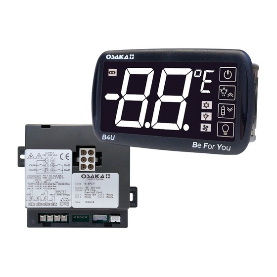
B4U
Display + Power Unit
INTUITIVE CONTROL PANEL
FOR REFRIGERATION
USER MANUAL - v1
INTRODUCTION
This manual contains the information necessary
for the correct installation and instruction for
use and maintenance of the product, it is
recommended that you read it carefully and
keep it.
This publication is the exclusive property of
SOLUTIONS, which prohibits reproduction and disclosure, even
partial, unless expressly authorized.
OSAKA SOLUTIONS reserves the right to make aesthetic and
functional changes at any time and without prior notice.
In order to avoid that an irregular operation of the B4U or
malfunction can create dangerous situations or damage to
people or things or animals, it is recalled that the installation
must comply with and take into account the attached security
systems, necessary to guarantee said security.
OSAKA SOLUTIONS and its legal representatives do not
assume any responsibility for damages to people, things or
animals derived from improper handling, improper use,
incorrect use or, in any case, non-compliance with the
characteristics of the B4U.
INDEX
5.8.1
5.8.2
5.8.3
5.8.4
5.8.5
5.10.1 TEMPERATURE ALARM
5.10.2 DIGITAL INPUT ALARM
5.10.3 DOOR OPEN ALARM
5.10.4 VOLTAGE CONTROL ALARM
5.12.1 PARAMETER CONFIGURATION BY "KEY USB" "
5.12.2 VIEWING THROUGH X2
5.12.3 RS485 COMMUNICATION WITH "KEY TTL"
OSAKA
1 - DESCRIPTION B4U
1.1 - GENERAL DESCRIPTION
The B4U model is an intuitive control panel that combines the Display
B4U (Display) plus the Power Unit B4U (power unit). It has a digital
microprocessor that can be used for temperature control in
refrigeration applications. It is prepared for the ON / OFF control and
defrost control, at intervals of time, to reach the temperature or for
the continuous operation of the compressor through the compressor
stop, electrical resistance or gas inversion / hot cycle.
The B4U has special functions to optimize defrost and functions that
can be used to achieve energy savings in the system.
The B4U has up to 4 relay outputs and 5 configurable inputs, of which
3 are for NTC temperature probes and 2 are digital for voltage-free
contacts.
OSAKA
- USER MANUAL - B4U - v2 - PAG. 1
1
DESCRIPTION B4U
1.1
GENERAL DESCRIPTION
1.2
DESCRIPTION DISPLAY B4U + POWER UNIT B4U
2
PROGRAMMING
2.1
QUICK CONFIGURATION OF THE SET POINT
"NORMAL"
2.2
STANDARD PARAMETER PROGRAMMING
2.3
PARAMETER PROTECTION THROUGH PASSWORD.
2.4
PARAMETER PROGRAMMING LEVELS
2.5
RESET THE FACTORY SETTINGS OF THE
PARAMETERS
2.6
KEYBOARD LOCK FUNCTION
2.7
VISUALIZATION OF THE VARIABLES
3
USE WARNINGS
3.1
PERMITTED USE
4
INSTALLATION WARNINGS
4.1
MECHANICAL ASSEMBLY
4.2
ELECTRICAL CONNECTION
5
FUNCTIONING
5.1
ON / STAND-BY FUNCTION
"NORMAL", "ECONOMIC" AND "TURBO" OPERATING
5.2
MODES
5.3
PROBE INPUTS AND DISPLAY CONFIGURATION
5.4
DIGITAL INPUTS CONFIGURATION
5.5
CONFIGURATION OF THE OUTPUTS AND BUZZER
5.6
TEMPERATURE REGULATION
5.7
COMPRESSOR PROTECTION AND START DELAY
FUNCTION
5.8
DEFROST CONTROL
AUTOMATIC DEFROST
MANUAL DEFROST
DEFROST END
INTERVAL AND DURATION OF DEFROST IN CASE OF
EVAPORATOR PROBE ERROR
DISPLAY LOCK IN DEFROST
5.9
EVAPORATOR FAN CONTROL
5.10
ALARM FUNCTIONS
KEYBOARD OPERATION "ON / OFF" AND "LIGHT"
5.11
5.12
ACCESSORIES
6
PROGRAMMABLE PARAMETERS TABLE
7
PROBLEMS, MAINTENANCE AND WARRANTY
7.1
SIGNALING
7.2
CLEANING
7.3
WARRANTY AND REPAIR
7.4
DISPOSAL
8
TECHNICAL DATA
8.1
FEATURES
ELECTRICAL
8.2
FEATURESMECHANICAL
8.3
FEATURESFUNCTIONAL
Advertisement
Table of Contents

Related Manuals for Osaka B4U

Summary of Contents for Osaka B4U
- Page 1 B4U. The B4U has up to 4 relay outputs and 5 configurable inputs, of which 3 are for NTC temperature probes and 2 are digital for voltage-free contacts.
- Page 2 11 - Unit of Measure Led: Indicates the temperature measurement unit in use. POWER UNIT B4U 1 - ON / OFF key: Pressing for 1 second turns the B4U on / off (Stand-by). Pressing for 5 seconds together with the LIGHT key (4), allows access to the parameter programming mode.
- Page 3 Once the desired value has been selected, press the LIGHT button password value that we programmed and press the LIGHT key to or wait 3 seconds for the B4U to activate the new set value and return confirm. to the normal operating screen.
- Page 4 A 90 x 44 mm hole must be made and the DISPLAY B4U must be Therefore if we do not press any key during the time "It"the B4U will inserted, fixing it with the special supports provided.
-
Page 5: Operation
Going from the Stand-By state to the ON state is exactly the same as turning on the B4U with the power supply. In case of power failure, the B4U returns to the function that was just before the power supply interruption. - Page 6 - Exiting ECONOMIC mode (only if "HC" = C3) increase (parameter "du") and for the decrease (parameter "dd") and - Every time the B4U is started (only if "HC" = C3 and Pr1 greater thus avoid showing a rapid change in temperature.
-
Page 7: Digital Input Configuration
Note: In the event that the digital input is configured for this type of = 3 - Activation by LIGHT key or digital input even when the B4U is function, the unit will consider the contacts as if they were in parallel in Stand-By. -
Page 8: Temperature Regulation
In this case, the regulation Set point for the "ot" output will be "SP", The B4U temperature control is ON / OFF and acts on the outputs "SE", "SH" while for the "HE" output it is through the Set "SH". -
Page 9: Defrost Control
"dE". During this delay phase we will display od alternating to the normal If you want to perform a defrost at each start-up of the B4U, program programmed display. the parameter "Sd" = oF. This will make a defrost immediately upon The “od”... -
Page 10: Manual Defrost
5 seconds, if the conditions are correct, the DEF to the shortest time programmed in the parameter relative to probe LED will light up and the B4U will carry out a defrost cycle. error conditions. To interrupt a defrost cycle in progress, press and hold the UP / These functions are available when the evaporator probes are used, DEFROST key for about 5 seconds. -
Page 11: Evaporator Fan Control
These parameters are: "1P" and "2P" - are the delay times of the temperature alarms at the start of the B4U, which if there are alarms at start-up, they will wait for the time programmed in these parameters to pass. - Page 12 By pressing the ON / OFF button for at least 1 second it is possible to change the state of the B4U from on to off and vice versa. By pressing the LIGHT button for at least 1 second it is possible to Or through the values ["SP"...
- Page 13 The X2 remote display device can be connected to the Power Unit CU Display offset ÷ 30 ° C / ° F B4U using a special cable that can have a maximum length of 10 meters. The X2 device, powered directly by the B4U, shows the Use of Pr2 input: temperature measured by the Pr1 probe through a 2 ½...
- Page 14 - 99 ÷ -9.9 ÷ 9.9 Defrost end temperature / 10 ÷ 99 ° C / ° (evaporator1) oF / -01 ÷ -59 Fd Fan delay after defrost (sec) ÷ 01 ÷ 99 (min) OSAKA - USER MANUAL - B4U - v2 - PAG. 14...
- Page 15 Au1 = Switching on the Temperature alarm type 2: 1/2/3/4/5/6/7/8/9 HE / 2d / L1 / L2 lights through the LIGHT see “1y” / -d / A2 button on the front OSAKA - USER MANUAL - B4U - v2 - PAG. 15...
- Page 16 7.3 - WARRANTY AND REPAIRS operating parameters with oF ÷ 99 This B4U has a warranty in the form of repair or replacement, for subdivisions into folders manufacturing defects in materials, within 12 months from the date Device address for of purchase.
-
Page 17: Mechanical Characteristics
B4U Display Connections: removable mini connectors. Power Unit B4U connections (power supply and outputs): removable 6-pole AMP MATE-N-LOK .250 "removable connector Connection Display B4U - Power Unit B4U: 3 m MAX. Through the cable with removable mini-connectors. Pollution degree: 2 Ambient operating temperature: 0…...
Need help?
Do you have a question about the B4U and is the answer not in the manual?
Questions and answers