Worcester W 125 FL Installation & Servicing Instructions Manual
Flueless singlepoint water heater with atmosphere - sensing device
Hide thumbs
Also See for W 125 FL:
- Installation and servicing instructions (29 pages) ,
- User instructions (17 pages)
Table of Contents
Advertisement
Quick Links
INSTALLATION AND
SERVICING INSTRUCTIONS
For your safety - if you smell gas:
1. Turn off the appliance
2. Open all windows and doors
This appliance conforms to European Standard EN 26.
It is the law that all gas appliances are installed by competent persons.
The following instructions should be read carefully as the manufacturer cannot be held responsible for any
damage to property, persons or animals caused by incorrect installation or operation of the appliance.
It is recommended that the appliance be serviced annually by a competent person or the local Gas Region.
The Users Instructions should be handed to the user and the function and operation of the appliance
explained.
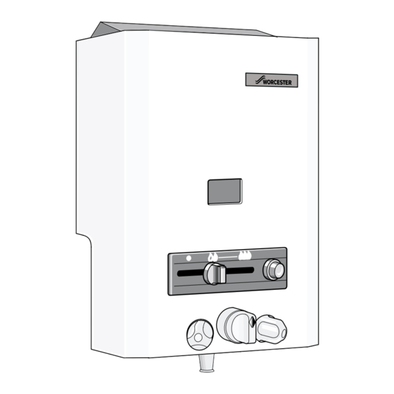
W 125 FL
Flueless Singlepoint Water Heater
with Atmosphere - Sensing Device
G.C. Nº 52-311-022
3. Do not operate any electrical switches
4. Extinguish all naked flames
5. Contact the local Gas Region immediately
Advertisement
Table of Contents

Subscribe to Our Youtube Channel
Related Manuals for Worcester W 125 FL


Summary of Contents for Worcester W 125 FL
- Page 1 W 125 FL Flueless Singlepoint Water Heater with Atmosphere - Sensing Device INSTALLATION AND SERVICING INSTRUCTIONS G.C. Nº 52-311-022 For your safety - if you smell gas: 3. Do not operate any electrical switches 1. Turn off the appliance 4. Extinguish all naked flames 2.
-
Page 2: Table Of Contents
To ensure that the installation will perform to the SAFETY FEATURES highest standards, the system and components should The Worcester W 125 is fitted with an atmosphere-Sensing conform to any other relevant British Standards in addition Device which must not be altered in any way. - Page 3 Appliance water flow diagram. Natural Gas Fig. 2 L.P.G. 14 Pilot gas pipe 30 Hot water outlet 44 Pilot gas filter 17 Large poppet valve 31 Volumetric water governor 47 Burner pressure test point 18 Small poppet valve 32 Temperature selector 49 Burner injector 19 Cross-ignition bolt 35 Gas inlet pipe...
- Page 4 Dimensions (in mm) Fig. 3 1 Flue gas deflector 6/2 Hot water tap 2 Observation window 7 Temperature selector 3 Front cover 8 Piezo ignitor 4 Output slide control 9 Water valve assembly 5 Water outlet 11 Gas valve assembly 6/1 Cold water tap 12 Heat exchanger...
-
Page 5: Technical Data
Technical Data Table 1 - GENERAL Natural Gas Minimum rated output (Pmin) 4.4 kW 4.4 kW Maximum rated output (Pn) 8.7 kW 8.7 kW Rated input (Qn) 10.4 kW 10.4 kW Gas rate (maximum) 0.8 kg/h 1.1 m Number of injectors Injector diameter (mm) 0.70 Pilot injector marking... -
Page 6: Gas Supply
Gas supply The appliance requires 1.1 m /hr of gas. The gas meter and supply pipes must be capable of supplying this quantity of gas in addition to the demand from any other appliances being served. Refer to BS 6891 for further information. The meter governor should deliver a dynamic pressure of 20 mbar (8 in w.g.) at the appliance. -
Page 7: Inspection And Service
d) Turn on the gas service cock. Re-light the appliance as described above. Turn the e) Move the gas control slide to the ignition position. See temperature control to maximum. fig. 6. i) Operate the appliance for at least two minutes, then check that the burner pressure is as stated in Technical Data –... -
Page 8: Replacement Of Parts
Take care not to damage the two ‘O’ ring seals. Replacement of Parts Unscrew the large heat exchanger retaining screw, located at the rear of the combustion chamber just The law requires that any service work must be carried above the burner blades, and lift clear the heat out by a competent person such as British Gas or other exchanger assembly. - Page 9 supply at the inlet cock. Open the taps to release any remaining water pressure and drain the appliance. c) Remove the water discharge pipe. d) Undo the union connection on the water isolating cock. e) Pull out the retaining clips at the inlet and outlet connections on the water control body, and spring out the copper inlet and outlet pipes from the control body.
-
Page 10: Spare Parts
Spare Parts Fig. 10... -
Page 11: Fault Finding
Parts List Description Propane Natural Gas Front Cover 8 705 411 730 8 702 000 219 Temp. Control Knob Flue gas Deflector 8 705 505 249 Heating Body 8 705 406 248 8 708 120 239 8 708 120 352 Main Burner Assembly 8 708 202 130 8 708 202 157... - Page 12 Worcester Heat Systems Limited, Cotswold Way, Warndon, Worcester WR4 9SW. Telephone: (01905) 754624. Fax: (01905) 754619 This booklet is accurate at the date of printing but will be superseded and should be disregarded if specifications and/or appearances are changed in the interests of continued improvement.
Need help?
Do you have a question about the W 125 FL and is the answer not in the manual?
Questions and answers