Table of Contents
Advertisement
Quick Links
Mounting and operating instructions
C O N T O I L
Table of contents
direct fuel consumption
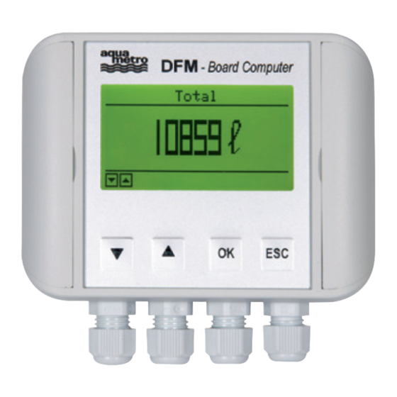
Board Computer (DFM 8D / 8S / 20S / 25S)
- For User ... daily information (User Mode)
- TRIP
- For Managers ... more and deeper information (Manager Mode)
- Configuration
(Information about Sensor Type, RL Sensor, User Reset)
(information about Total, TRIP, Current l/h, Op. Hours)
(information about Total, TRIP, Current l/h, Op. Hours)
(results from Supply Line minus Return Line)
®
D F M
2
3
4
5
7
8
9
10
11
For Service Peoples ... parameter setting (Service Mode)
- The Board Computer (DFM-BC) is running, but no value from
the Sensors.
18
20
20
21
23
25
26
28
28
Advertisement
Table of Contents

Subscribe to Our Youtube Channel
Related Manuals for aqua metro CONTOIL DFM


Summary of Contents for aqua metro CONTOIL DFM
-
Page 1: Table Of Contents
Mounting and operating instructions C O N T O I L ® D F M Table of contents For Service Peoples … parameter setting (Service Mode) - Entering the Service Mode - Entry Code Safety instructions - Configuration (Sensor Type, Return Line Sensor, User Reset, AUX) - Designed use - Supply Line (Total, TRIP, Current) - Installation, commissioning and operation... -
Page 2: Safety Instructions
Safety instructions Designed use This unit is designed for acquisition, calculation, displaying and sending datas. Resulting from incorrect use or from use other than that de- signated, can suspend the operational safety of the devices. The manufacturer accepts no liability for damages being produced from this. Installation, commissioning and operation Installation, connection to the electricity supply, commissioning and maintenance of the device must be carried out by trained, qualified spe- cialists authorised to perform such works. -
Page 3: Configuration Overview
Configuration overview Schematic of a configuration Tank Engine Mechanical injection pump Fine filter Preliminary Pump filter Fleet Manager Battery The 2 sensor meter are just an example. They can be changed with a compact one. Installation Advices • The sensors have to be always protected by a fuel filter. The max. mesh size depends on the sensor size. The original truck filter is ide- al for all sensor sizes. -
Page 4: How To Connect The
How connect the... Before you start with the electrical connection of the system, you must have done a correct installation of the delive- red components. This installation must be done by an authorized and certified company/person. Please be aware: an incorrect installation may destroy the DFM-System and damage your vehicle. In this case, Aqua- metro will deny all responsibilities. -
Page 5: Single Flow-Sensors To The Board Computer
11. Set the <SL KF> and the <SL app>. a. Starting from the previous position, press many time the down-arrow, until you reach the menu point “Supply configuration”. b. Press <OK> at the menu point “SL KF”. Enter the value for the <SL KF> using the arrow keys. This value is prin- ted on the type plate of the flow meter. - Page 6 Return-Line Sensor DFM-Sensor - cable colors DFM-BC - positions on the connector Black Brown Yellow Green Not used White Not used 5. To ensure a proper function, the cable, described in the procedure below, must be connected direct to the vehicle battery.
-
Page 7: Single Flow-Sensors To The Board Computer For
13. Set the time a. Move with the down-arrow key to the line “Time”. b. On the line “Time”, press <OK>. Modify the time by using the down-arrow or the up-arrow. Move from left to right with the <OK> key and from right to left with the <ESC> key. c. -
Page 8: Board Computer (Dfm-Bc) To A Fleet Manager Or
9. Input Value and Output Value Change the “Input Value” by doing the following: a. Press the down-arrow b. On the “Input” line press <OK> c. The field “Input xxxx.x ml” will by highlighted. d. Press the down-arrow or the up-arrow to adjust the “Input Value” according to the table “Sensor Type” e. -
Page 9: Gps Tracking System
1. With the DFM-BC in front of you, open the side-wings of the box and unscrew the 4 screws. Put the upper part of the DFM-System gently by side. Be CAREFULL. The upper part is connected to the base part with a flat cable. 2. -
Page 10: Startup (Commissioning)
Setting of the DFM-BC Start with the settings of the DFM-BC by doing the following: 1. Take the DFM-BC. If it is off, press one of the 4 Keys on the front to reactivate it. Go to the menu point <Service>. Press <OK> and enter the Service-Code Standard service code is: 1111 2. -
Page 11: Operating Instruction For The Board Computer (Dfm-Bc)
9. Go to the <Supply Configuration> a. Check the <SL KF>. Is it the right one? b. If not, go back to the section <How to connect …> and take the appropriate corrections. 10. Go to the <Return Configuration> a. Check the <RL KF>. Is it the right one? b. -
Page 12: Consumption
Consumption This picture shows the current consumption of the Engine in l/h. Previous screen Next screen The next two screens (Info Mode and Service Mode) are explained in the section For Managers and For Service People. Display Test Press OK to start the Display test. Previous screen Next screen This will start the Display test. -
Page 13: Supply Line
Supply Line (information about Total, TRIP, Current l/h, Op. Hours) Total: amount of liter that has flew through this sensor since the commissioning TRIP: amount of liter since the last reset (it functions like a daily counter) Current: actually flow rate in l/h Op. -
Page 14: Config Log Entry
Config Log Entry The DFM-BC has the ability to store all configuration changes which happened. If the allowed entries are exceeded, the oldest one will be deleted. This screen shows you, when the last configuration change was recorded. Press OK to enter the Config Log. Config Log This screen shows you, with data and time stamp, the last stored configuration change in a readable way. -
Page 15: Entering The Service Mode
Entering the Service Mode Press OK to enter the Service mode Entry Code After entering the Service Mode, a code is requested Enter the 4 digit code and press OK Use the arrow key to change values. • The standard service code is: 1111. •... -
Page 16: Supply Line (Total, Trip, Current)
Supply Line (Total, TRIP, Current) Move the bar over the line you would like to change parameters. Press OK. The changeable field will be highlighted for changing. This action will be followed by security questions. Answer the question with YES or NO until the value will be changed. Total: Reset of the total amount of the fuel which is passed through the supply line since commissio- ning. -
Page 17: Error Log Entry
Error Log Entry Press OK to enter the error log Read the stored Error Messages (Error Log) With the arrow and the arrow you can scroll through the messages Each message has a data and time stamp. After the last message is reached the first message will be showed. -
Page 18: Factory Data
Factory data No changes are possible. The displayed information is needed for updates or internal use. Error condition Error Messages If an error has occurred and it has consequence for the following digital readouts Total or TRIP or the Consumption than the Board Computer (DFM-BC) will show the following on the display: ...and after 5 seconds... -
Page 19: Description Of The Error Messages
Description of the Error Messages In any case, if an error occurs look at the Error Log to define what exactly happened and at what time. To check the installation is also a recommended approach for founding faults. The following messages will be displayed if an error occurs: S>0 &R=0 Supply line Sensor has a flow rate. -
Page 20: Higher Performance Results (With Application Optimization)
Higher Performance Results (with application optimization) High Performance Results means, to adapt the system to the different condition you can face during your daily work. This can be: 1. High ambient temperatures. 2. Low ambient temperatures. 3. Different temperatures between supply line and return line of the fuel system. 4. -
Page 21: Electrical Connections And Specifications
Electrical Connections and Specifications For the DFM-8D Explanation of the wires: Black Input voltage 12-24 VDC from the DFM-BC or from another source. If you use another source, make sure the voltage is stable and filtered Brown Ground (take the same ground like the 12-24 VDC source). Yellow “Supply Line Right”... - Page 22 Pin 11: Signal for the external device Connect here the Analog/Digital cable from the Fleet-Manager or GPS-Tracking-System. Attention: the signal is a pull down transistor, that means, whenever a signal should be generated, this line will go to ground (Open Drain). Pin 12: Ground for the external device.
-
Page 23: Electrical Scheme Of The Dfm Systems
Electrical scheme of the DFM Systems DFM-BC to DFM 8D DFM-BC DFM 8D 18598 l Battery Batt . - Black Batt .+ Brown Yellow Green White DFM-BC to DFM 8S / 20S / 25S for differential consumption Supply Line Red and White DFM-BC are not used Black... - Page 24 DFM-BC to DFM 8S / 20S / 25S for direct consumption Red and White Supply Line DFM-BC are not used 18598 l Black Brown Yellow Battery Green Batt . - Batt .+ DFM-BC to Fleet Manager or GPS-Tracking System DFM-BC 18598 l Battery Flow Meter...
-
Page 25: Specification And Technical Data
DFM-BC to VZF(A) for differential consumption DFM-BC Supply Line Terminal strip VZF(A) inside VZF(A) 18598 l Battery Return Line Terminal strip VZF(A) inside VZF(A) Batt. - Batt.+ Fleet- Input - Manager Interface Input + Specification and Technical Data Flow sensors DN 8 DN 20 DN 25... -
Page 26: Dimensions
Board Computer Power supply 12…24 VDC direct from vehicle battery Registration 100.000.000 litres Scale value Default for DN 8 = 80 pulses per liter Temperature Ambient –10 ... +70 °C, Protection class IP 54 according to IEC 60529 Electrical connection Power supply with cable 2 x 0.75 mm , 2 m supplied Cable outer diameter 5.0 mm... -
Page 27: Dfm-Bc
DFM-BC 90 mm 120 mm 99 mm 63 mm CONTOIL ®... -
Page 28: Ordering Information
Ordering Information Description Type Part. no. Diesel fuel flow sensor DN 8D (double) DFM8D 94465 Diesel fuel flow sensor DN 8S (single) DFM8S 94464 Diesel fuel flow sensor DN 20S (single) DFM20S 94466 Diesel fuel flow sensor DN 25S (single) DFM25S 94467 Board Computer...
Need help?
Do you have a question about the CONTOIL DFM and is the answer not in the manual?
Questions and answers