Table of Contents
Advertisement
Quick Links
smartsystem
SmartMonitor information
i
i
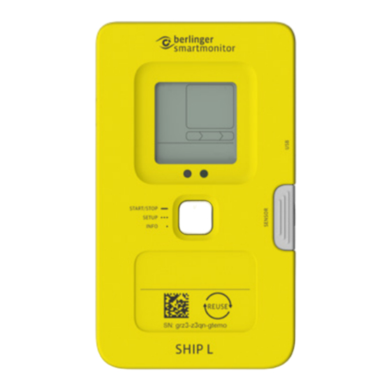
Device layout
11
10
9
8
7
Centered hook for mounting on device backside.
Device installation
1
Depending on the application, the SmartMoni-
tor is used with or without an external sensor.
If you require application advice, reach out to:
support@berlinger.com.
With external sensor
1. Position the external
sensor head inside (1) and
the SmartMonitor outside
(2) the temperature-con-
trolled box/container and
wait for the external sensor
to acclimatize.
Without external sensor
Position the
SmartMonitor inside
the temperature-
controlled box/
container and wait
for the device to
acclimatize.
To complete the configuration of the
SmartMonitor, proceed with step 2.
The screen is indicating that the configuration
download is initiated and all display icons are
loading. This might take several seconds.
If the display indicates MANUAL, automatic
download was not successful.
12
1
2
3
4
5
6
2. Remove the grey
cap on the right side
of the SmartMonitor.
While the device is
establishing connection
to SmartView, the tick in
the cloud symbol ( ) is
blinking and the cellular
symbol ( ) is static.
Once the download is
successfully completed,
the configuration policy
name of your desired
configuration policy is
displayed.
Learn More
User Manual SmartMonitor
For more information scan the QR code
or visit www.berlinger.com/user-manual-smartmonitor.
QUICK INFO
SmartMonitor SHIP L
SmartMonitor SHIP M
1
Display
2
USB-plug
3
LED
Removeable cap
4
5
Device use
6
Device type
Available icons on device display
Battery charging
Battery status
Cloud status
Warning
symbol
USB
Bluetooth
Warning: Do not
apply force!
4. Once correctly
applied, tighten the
connector by screw-
ing clockwise.
How to configure your
2
device
Automatic configuration
1. Short-press the multifunctional button to
"wake up" the SmartMonitor from sleep mode.
The SmartMonitor must be fully charged upon
Manual configuration
If the device cannot connect to SmartView to
download the configuration, it is required to
manually download the configuration file to
the device via USB.
Follow the instructions in the user manual to
set up the configuration manually.
Need help with Manual configuration?
See user manual
7
Serial number
8
GTIN barcode
Multifunctional button
9
10
Light sensor
11
Humidity sensor
12
Sensor socket (M5)
Cellular connection
Alarm status
Measurement
status
7-digit text field
3. Align the sensor
plug with the sensor
socket. Ensure the
Berlinger eye is
facing the same
direction as the
SmartMonitor
display. Now, plug
the external sensor
into the sensor
socket.
2. To configure the device
with the desired config-
uration, triple push the
multifunctional button in
quick succession.
This will initiate cloud syn-
chronization to download
the configuration.
device start.
«How to configure your
12
device»
Advertisement
Table of Contents

Related Manuals for berlinger SmartMonitor SHIP L

Summary of Contents for berlinger SmartMonitor SHIP L
- Page 1 QUICK INFO SmartMonitor SHIP L SmartMonitor SHIP M SmartMonitor information Display Serial number GTIN barcode USB-plug Device layout Multifunctional button Removeable cap Light sensor Device use Humidity sensor Device type Sensor socket (M5) Available icons on device display Cellular connection...
- Page 2 SmartView and symbol is blinking. the restart procedure has been completed, the SmartMonitor SHIP L is ready for re-use. Log into SmartView and locate the device that you would like to re-start under the tab “Moni- All data has been uploaded toring”, “Devices”.
Need help?
Do you have a question about the SmartMonitor SHIP L and is the answer not in the manual?
Questions and answers