Hoval TopVent TP Operating Instructions Manual
Hide thumbs
Also See for TopVent TP:
- Operating instructions manual (48 pages) ,
- Operating instructions manual (56 pages)

Subscribe to Our Youtube Channel
Related Manuals for Hoval TopVent TP


Summary of Contents for Hoval TopVent TP
- Page 1 I n d o o r c l i m a t e s y s t e m s Hoval TopVent ® Operating instructions Original operating manual 4 218 024-en-04 Hoval | Responsibility for energy and environment...
-
Page 2: Table Of Contents
TopVent ® Content 1 Use 7 Transport and installation 1.1 Intended use ....3 7.1 Scope of delivery ....26 1.2 User group . -
Page 3: Use
TopVent ® 1 Use 1.1 Intended use TopVent ® TP units are recirculation units intended for heating and cooling spaces up to 25 m in height with decentralised heat pump. They have the following functions: ■ Heating and cooling with heat pump ■... -
Page 4: Safety
TopVent ® Safety 2 Safety 2.1 Symbols Caution This symbol warns against risk of injury. Please heed all instructions designated by this symbol to prevent injuries and/or death. Attention This symbol warns against property damage. Please heed the respective instructions to prevent risk of damage to the unit and its functions. Notice This symbol denotes information about the economic use of the equipment or special tips. -
Page 5: Construction And Operation
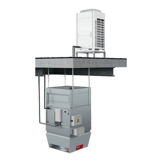
TopVent ® Construction and operation 3 Construction and operation 3.1 Construction The TopVent ® TP unit consists of the following components: ■ Recirculation unit ■ Heat pump system ■ Recirculation unit a Flat filter box (option) b Supplementary heater (option) c Heating/cooling section d Air-Injector ■... -
Page 6: Construction Variants
TopVent ® Construction and operation 3.2 Construction variants ■ Actuator Air-Injector ■ Condensate connection ■ Expansion valve ■ Condensing unit ■ Condenser/evaporator ■ Condensate separator ■ Fig. 2: TopVent TP with 1 heat pump system ® 4 218 024-en-04... - Page 7 TopVent ® Construction and operation ■ 2 condensing units ■ Condenser/evaporator with 2 circuits ■ 2 communication modules ■ 2 expansion valves Fig. 3: TopVent ® TP with 2 heat pump systems ■ Flat filter box ■ Access panel, electric heating coil connection ■...
-
Page 8: Function Diagrams
TopVent ® Construction and operation 3.3 Function diagrams TopVent ® TP with 1 heat pump system TopVent ® TP with 2 heat pump systems TP-6-K TP-9-K TP-9-M ■ ■ Extract air Extract air ■ ■ Air filter with differential pressure switch (optional) Air filter with differential pressure switch (optional) ■... - Page 9 TopVent ® Construction and operation TopVent ® TP with supplementary heater (electric heating coil) TopVent ® TP with supplementary heater (hot water) TP-6SK TP-9RK TP-6AK TP-9SK TP-9AK ■ ■ Extract air Extract air ■ ■ Air filter with differential pressure switch (required) Air filter with differential pressure switch (optional) ■...
-
Page 10: Operating Modes
TopVent ® Construction and operation 3.4 Operating modes The TopVent ® TP has the following operating modes: ■ Recirculation ■ Recirculation speed 1 ■ Standby The TopTronic ® C control system regulates these operating modes automatically for each control zone in accordance with the specifications in the calendar. The following points also apply: ■... -
Page 11: Type Code
TopVent ® Type code 4 Type code TP - 6 A K / ST . D1 / S . FK . LH . U- / Y . KP / TC . - . PH . RF Unit type TopVent ® Unit size 6 or 9 Heating section... - Page 12 TopVent ® Type code TP - 6 A K / ST . D1 / S . FK . LH . U- / Y . KP / TC . - . PH . RF Condensate pump without Condensate pump Control system TopTronic ®...
-
Page 13: Technical Data
TopVent ® Technical data 5 Technical data 5.1 Application limits Fresh air temperature heating mode min. °C max. °C Fresh air temperature cooling mode min. °C max. °C Extract air temperature max. °C Moisture content of extract air max. g/kg Supply air temperature max. -
Page 14: Electrical Connection
TopVent ® Technical data 5.2 Electrical connection TopVent ® Unit type TP…6K TP-9…K TP-9-M Supply voltage V AC 3 × 400 Permitted voltage tolerance ± 5 Frequency Connected load Current consumption max. Series fuse 13.0 Table 7: TopVent TP electrical connections ®... -
Page 15: Air Flow Rate
TopVent ® Technical data 5.3 Air flow rate Unit type TP-6 TP-9 Nominal air flow rate m³/h 6000 9000 Floor area covered m² Table 10: Air flow rate 5.4 Condensing unit technical data Rated heat output 31.5 Rated cooling capacity 28.0 COP value –... -
Page 16: Heat Output
TopVent ® Technical data 5.6 Heat output Type Δp room °C °C °C 6–K 22.0 15.8 28.9 7.77 – – – 32.1 13.5 33.9 8.45 – 295.0 33.9 13.2 34.8 8.58 12.1 – – 9–K 22.0 19.6 25.3 7.77 – –... -
Page 17: Dimensions And Weights
TopVent ® Technical data 5.8 Dimensions and weights TopVent ® TP with 1 heat pump system ■ Gas line connection (∅ 22.2 mm) Unit type TP-6-K TP-9-K ■ Liquid line connection (∅ 9.5 mm) 1100 ■ Condensate connection (G1" external) ■... - Page 18 TopVent ® Technical data TopVent ® TP with 2 heat pump systems ■ Gas line connection – circuit 1 (∅ 22.2 mm) Unit type TP-9-M ■ Gas line connection – circuit 2 (∅ 22.2 mm) 1100 ■ Liquid line connection – circuit 1 (∅ 9.5 mm) ■...
- Page 19 TopVent ® Technical data TopVent ® TP with supplementary heater (electric heating coil) and flat filter box ■ Access panel, electric heating coil Unit type TP-6SK TP-9RK ■ TP-9SK Gas line connection (∅ 22.2 mm) ■ 1100 Liquid line connection (∅ 9.5 mm) ■...
- Page 20 TopVent ® Technical data TopVent ® TP with supplementary heater (hot water) ■ Return Unit type TP-6AK TP-9AK ■ Flow 1100 ■ Gas line connection (∅ 22.2 mm) ■ Liquid line connection (∅ 9.5 mm) ■ Condensate connection (G1" external) ∅...
- Page 21 TopVent ® Technical data Condensing unit ■ Electrical connection box Unit type ERQ250 ■ Working medium circuit connection (front or bottom) Weight ■ Cable feedthroughs Table 16: Dimensions and weights of the Daikin ERQ250 condensing unit 4 218 024-en-04...
-
Page 22: Options
TopVent ® Options 6 Options 6.1 Suspension set A suspension set is available to make it easy to install the units on the ceiling. The set consists of 4 pairs of U-profiles made of magnesium zinc sheet and is height-adjustable up to 1300 mm. 6.2 Air filtration Caution Risk of fire due to dust in the air. -
Page 23: Paint Finish
TopVent ® Options Flat filter box A flat filter box with 4 pleated cell filters can be installed for the purpose of filtering the recirculation air. A pressure difference control device is installed for automatic monitoring of the filter. It shows when the filters have to be changed. Size 1100 Standard... -
Page 24: Hydraulic Assembly Diverting System
TopVent ® Options 6.5 Hydraulic assembly diverting system An assembly for the hydraulic diverting system is included in the delivery. It consists of the following components: ■ Automatic air vent ■ Coil screw joint ■ Control valve ■ Distributor circuit screw joint ■... -
Page 25: Pump Control
TopVent ® Options 6.9 Pump control Instead of the diverting system, a mixing or injection circuit can also be installed in the load circuit. Please note the following: ■ Not only the mixing valves but also the pumps in the load circuit are controlled directly by the unit control box. -
Page 26: Transport And Installation
TopVent ® Transport and installation 7 Transport and installation Caution Risk of injury from incorrect handling. Transport, assembly and installation work may only be performed by specialists. Observe safety and accident prevention regulations. 7.1 Scope of delivery The scope of delivery includes: ■... -
Page 27: Storage
TopVent ® Transport and installation Condensing unit ■ Lifting the condensing unit with a crane: – Use 2 straps at least 8 m in length. ■ Lifting the condensing unit with a forklift: – Transport to the installation site: Lift the unit under the pallet. –... - Page 28 TopVent ® Transport and installation Condensing unit ■ Comply with the minimum distances for free air entry: 0.6 m at the front side and 0.2 m to the left and right. ■ The outgoing air jet must be free to spread upwards unhindered. ■...
-
Page 29: Installation
TopVent ® Transport and installation 7.4 Installation Caution Risk of injury caused by falling load and improper handling. During installation: – Wear personal protective equipment. – Do not stand under suspended loads. – Use cranes or forklifts with sufficient load-bearing capacity. Preparation ■... - Page 30 TopVent ® Transport and installation Mounting the heat pump system ■ Transport the condensing unit to the installation site. ■ Place the unit on the prepared frame. ■ Fasten the unit with 4 M12 anchor bolts. ■ Follow the installation instructions included. Mounting the condensate drain pan The condensate drain pan for the condensing unit (optional) is supplied separately and must be mounted on the bottom of the unit at the building site:...
- Page 31 TopVent ® Transport and installation Mounting the protection hoods Protection hoods for the condensing unit (optional) are supplied in 3 parts, comprising 2 side panels and 1 cover panel. They must be fitted to the unit at the building site. The installation material is provided. Proceed as follows: ■...
-
Page 32: Refrigeration System Installation
TopVent ® Transport and installation 7.5 Refrigeration system installation The refrigerant pipes must be installed by a qualified refrigeration technician in line with the local regulations. Make sure that the following is available. Refrigerant pipes ■ Liquid line: ∅ 9.5 mm, annealed copper Gas line: ∅... - Page 33 TopVent ® Transport and installation ■ Install the gas temperature sensor: – Fasten the sensor to the gas line, as close as possible to the condenser/ evaporator. – Ensure that the connection between the sensor and the gas line provides good conductivity.
- Page 34 TopVent ® Transport and installation Refrigerant pipes for TopVent ® TP with 1 heat pump system ■ Gas line (∅ 22.2 mm) ■ Liquid line (∅ 9.5 mm) ■ Expansion valve (fitted at the factory) ■ Connection pipe (supplied loose) 5 m …...
-
Page 35: Hydraulic Installation
TopVent ® Transport and installation 7.6 Hydraulic installation Hydraulic installation of units with supplementary heater with hot water (optional) ■ Connect the heating coil according to the hydraulic circuit diagram. ■ Depending on local conditions, check whether compensators for linear expan- sion are required for the supply and return lines and/or articulated connections are required for the units. -
Page 36: Condensate Connection Topvent
TopVent ® Transport and installation 7.7 Condensate connection TopVent ® Condensate arising in cooling units must be removed via a condensate-proof line. ■ Install and insulate the supplied trap on the condensate connection of the unit. ■ Dimension the slope and cross-section of the condensate line so that no condensate backflow takes place. -
Page 37: Electrical Installation
TopVent ® Transport and installation 7.9 Electrical installation Caution Danger of electric shocks. The electrical installation must only be carried out by a qualified electrician. Please note the following: ■ Observe all relevant regulations (e.g. EN 60204-1). ■ Choose the dimensions of the cable cross sections in line with the applicable regulations. - Page 38 TopVent ® Transport and installation Electrical installation for TopVent ® TP with 1 heat pump system ■ Condensing unit main switch with auxiliary contact (NO contact, provided by the client) ■ Power supply for condensing unit ■ Communication TopVent ® ■...
- Page 39 TopVent ® Transport and installation ■ Gas temperature sensor ■ Condensate pump (option) ■ Expansion valve ■ Liquid temperature sensor ■ Actuator Air-Injector ■ Supply air temperature sensor ■ Unit control box ■ Fan (signals, power supply) ■ Communication module ■...
- Page 40 TopVent ® Transport and installation TopVent ® TP with supplementary heater (electric heating coil) ■ Connect the power supply: – Open the access panel for the electric heating coil connection. – Mount the cable feedthrough fastened inside it in the side wall. –...
- Page 41 TopVent ® Transport and installation Condensing unit ■ Install a leakage current protective circuit for the condensing unit power supply. ■ Install a main switch with auxiliary contact (NO contact, provided by the client) in view of the condensing unit. ■...
-
Page 42: Operation
TopVent ® Operation 8 Operation 8.1 Initial commissioning Attention Risk of damage to property as a result of performing initial commissioning on your own authority. Initial commissioning must be performed by the manufacturer’s customer service technicians . Checklist to prepare for commissioning: ■... -
Page 43: Maintenance And Repair
Following maintenance work, professionally reassemble all dismantled protec- tive devices. ■ Replacement parts must comply with the technical requirements of the unit Notice manufacturer. Hoval recommends the use of original spare parts. The condensing unit main switch is installed by the client. 9.2 Maintenance Maintenance schedule... -
Page 44: Repair
■ Dispose of the filters in accordance with local regulations. – The disposal of used filters depends on the contents. 9.3 Repair If required, contact Hoval customer service. Product service life Component Service life EC motor of the fan approx. -
Page 45: Dismantling
TopVent ® Dismantling 10 Dismantling Caution Risk of injury caused by falling load and improper handling. – Wear protective equipment (fall protection, helmet, safety shoes). – Do not stand under suspended loads. – Use cranes or helicopters with sufficient load-bearing capacity. –... - Page 46 4 218 024-en-04...
- Page 47 4 218 024-en-04...
- Page 48 TopVent ® Operating instructions International Hoval Aktiengesellschaft 9490 Vaduz Liechtenstein Tel. +423 399 24 00 info.klimatechnik@hoval.com www.hoval.com United Kingdom Hoval Ltd. Northgate, Newark Notts NG24 1JN Tel. 01636 672711 hoval@hoval.co.uk www.hoval.co.uk 4 218 024-en-04...
Need help?
Do you have a question about the TopVent TP and is the answer not in the manual?
Questions and answers