Table of Contents
Advertisement
Quick Links
Advertisement
Table of Contents

Related Manuals for Belimo 22PDP


Summary of Contents for Belimo 22PDP
- Page 1 Operating instructions 22PDP differential pressure sensor Edition 2022-04/A...
- Page 2 22PDP differential pressure sensor...
-
Page 3: Table Of Contents
Table of contents Page Introduction General 4 Warning instructions 4 Prior to installation 4 Mounting Mounting the housing 5 Installation Stainless steel pressure transmitters 6 Pressure transmitters 6 Pressure transmitter cables 7 Configuration 8 Warning notice 8 Wiring Port wiring 9 Starting mode Software Version Number... -
Page 4: Introduction
Ensure that the maximum connection or system pressure does not exceed the value specified as the highest pressure for the respective sensor. This corre- sponds, for example, to a maximum of 10 bar for the 22PDP-186 sensor model. Measurement inaccuracies could occur if the sensor is operated in the over- pressure range. -
Page 5: Mounting
22PDP differential pressure sensor / Mounting Mounting Mounting the housing The sensor is mounted on a vertical surface with the mounting plate provided. The grey mounting plate can be detached from the housing and can be used as a drilling template. The four fastening holes of the mounting plate enable fasten- ing with corresponding screws (is included in the scope of delivery). -
Page 6: Installation
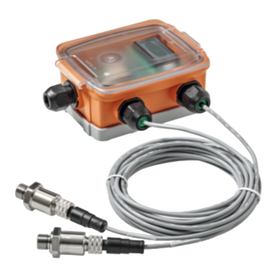
22PDP differential pressure sensor / Installation Installation Stainless steel pressure The two remote stainless steel pressure transmitters and the corresponding transmitters connecting cable ends are marked HIGH (connection for high pressure) and LOW (connection for low pressure). The output signal shows a positive value when the pressure applied at the HIGH connection is greater than that at the LOW connection. -
Page 7: Pressure Transmitter Cables
22PDP differential pressure sensor / Installation Pressure transmitter cables Prepare the G¼" pressure transmitter external thread with a suitable sealing material, e.g. Teflon tape, and screw the pressure transmitter hand-tight into the pipe to be monitored. Use a screw wrench of suitable size to tighten the pres- sure transmitter securely. -
Page 8: Configuration
22PDP differential pressure sensor / Installation Configuration Configuration is carried out to a large extent via the user menu settings in the LCD display and via the push buttons on the circuit board. For further informa- tion, consult the User menu section. -
Page 9: Wiring
22PDP differential pressure sensor / Wiring Wiring Port wiring To avoid electric shock or device damage, deactivate the 24 V AC/DC power supply until all of the connections to the device have been properly made. Use shielded cables with corresponding core cross-sections for all connections and do not route the device cables in the same conduit as the cables for supply- ing inductive loads, e.g. - Page 10 22PDP differential pressure sensor / Wiring Figure 10 In the event of a separate power supply, ensure that the grounding (DC) or supply common (AC) are connected from the sensor, the controller and the power supply. Subject to technical modifications...
-
Page 11: Starting Mode
22PDP differential pressure sensor / Starting mode Starting mode The device switches into starting mode when it is supplied with current. The LCD displays the current operating settings for 2 seconds. All of the information in the menu and in the display are in English. -
Page 12: User Menu
22PDP differential pressure sensor / User menu User menu The user menu can be entered at any time after starting mode by pressing the <MENU> button. Please note that the <ZERO> button function changes to an <UP> button function when a menu is active. -
Page 13: Pressure Range
22PDP differential pressure sensor / User menu 2. Pressure Range P Range 10 Bar The pressure range is set by default to the largest range (1) of the model. Use <DOWN> or <UP> to scroll through the four available model-specific ranges. -
Page 14: Output (Output Signal Direct/Reverse)
22PDP differential pressure sensor / User menu 5. Output Output (output signal direct/reverse) Direct The analogue output is set by default to direct (4...20 mA, 0...5 V or 0...10 V). <DOWN> or <UP> can be used to change this to reverse (20...4 mA, 5...0 V or 10...0 V). -
Page 15: Commissioning
22PD differential pressure sensor / Commissioning Commissioning Standard mode In standard mode, the device reads out the pressure transmitter and calculates the differential pressure depending on the selected range. The differential pres- sure is displayed on the LCD and is provided as current or voltage at the ana- logue output. - Page 16 Belimo Tested quality does indeed include everything. The “small” Belimo devices have a big impact on comfort, energy effi- ciency, safety, installation and maintenance. Short delivery times In short: Small devices, big impact.
Need help?
Do you have a question about the 22PDP and is the answer not in the manual?
Questions and answers