Table of Contents
Advertisement
Quick Links
SECTION 1 - GENERAL INFORMATION . . . . . . . . . . . . . . . . . . . . . . . . . . . . . . . . . . . . . . . - 1 -
1.1
INTRODUCTION . . . . . . . . . . . . . . . . . . . . . . . . . . . . . . . . . . . . . . . . . . . . . . . . . - 1 -
1.2
PRINCIPLE OF OPERATION . . . . . . . . . . . . . . . . . . . . . . . . . . . . . . . . . . . . . . . - 2 -
1.3
TECHNICAL SPECIFICATIONS . . . . . . . . . . . . . . . . . . . . . . . . . . . . . . . . . . . . . - 2 -
1.4
PRECAUTIONS . . . . . . . . . . . . . . . . . . . . . . . . . . . . . . . . . . . . . . . . . . . . . . . . . . - 2 -
SECTION 2 - INSTALLATION . . . . . . . . . . . . . . . . . . . . . . . . . . . . . . . . . . . . . . . . . . . . . . . . - 4 -
2.1
INTRODUCTION . . . . . . . . . . . . . . . . . . . . . . . . . . . . . . . . . . . . . . . . . . . . . . . . . - 4 -
2.2
RheoVac MONITOR INSTALLATION/SITE SELECTION . . . . . . . . . . . . . . . . - 4 -
2.2.1 Transducer Site Selection . . . . . . . . . . . . . . . . . . . . . . . . . . . . . . . . . . . . . - 4 -
2.2.2 Electronics Unit Site Selection . . . . . . . . . . . . . . . . . . . . . . . . . . . . . . . . . - 4 -
2.3
MOUNTING HARDWARE INSTALLATION . . . . . . . . . . . . . . . . . . . . . . . . . . - 6 -
2.4
TRANSDUCER INSTALLATION . . . . . . . . . . . . . . . . . . . . . . . . . . . . . . . . . . . . - 6 -
2.5
ELECTRICAL CONNECTIONS . . . . . . . . . . . . . . . . . . . . . . . . . . . . . . . . . . . . . - 8 -
2.6
RheoVac MONITOR GROUNDING . . . . . . . . . . . . . . . . . . . . . . . . . . . . . . . . . - 13 -
SECTION 3 - OPERATION . . . . . . . . . . . . . . . . . . . . . . . . . . . . . . . . . . . . . . . . . . . . . . . . . . - 15 -
3.1
GENERAL INFORMATION . . . . . . . . . . . . . . . . . . . . . . . . . . . . . . . . . . . . . . . - 15 -
3.2
SYSTEM START-UP . . . . . . . . . . . . . . . . . . . . . . . . . . . . . . . . . . . . . . . . . . . . . - 15 -
3.3
OUTPUT SIGNALS . . . . . . . . . . . . . . . . . . . . . . . . . . . . . . . . . . . . . . . . . . . . . . - 15 -
3.4
IBM-PC SOFTWARE . . . . . . . . . . . . . . . . . . . . . . . . . . . . . . . . . . . . . . . . . . . . . - 16 -
3.4.1 SOFTWARE INSTALLATION . . . . . . . . . . . . . . . . . . . . . . . . . . . . . . . - 17 -
3.4.2 SOFTWARE OPERATION . . . . . . . . . . . . . . . . . . . . . . . . . . . . . . . . . . - 17 -
3.4.3 DATA PROCESSING . . . . . . . . . . . . . . . . . . . . . . . . . . . . . . . . . . . . . . . - 18 -
3.5
CUSTOM SOFTWARE . . . . . . . . . . . . . . . . . . . . . . . . . . . . . . . . . . . . . . . . . . . - 19 -
SECTION 4 - MAINTENANCE . . . . . . . . . . . . . . . . . . . . . . . . . . . . . . . . . . . . . . . . . . . . . . . - 21 -
4.1
GENERAL MAINTENANCE . . . . . . . . . . . . . . . . . . . . . . . . . . . . . . . . . . . . . . . - 21 -
4.2
CALIBRATION . . . . . . . . . . . . . . . . . . . . . . . . . . . . . . . . . . . . . . . . . . . . . . . . . . - 21 -
4.3
SPARE PARTS . . . . . . . . . . . . . . . . . . . . . . . . . . . . . . . . . . . . . . . . . . . . . . . . . . - 21 -
4.4
TROUBLE SHOOTING . . . . . . . . . . . . . . . . . . . . . . . . . . . . . . . . . . . . . . . . . . . - 21 -
SECTION 5 - CUSTOMER SERVICE . . . . . . . . . . . . . . . . . . . . . . . . . . . . . . . . . . . . . . . . . - 25 -
5.1
QUESTION ON EXISTING HARDWARE . . . . . . . . . . . . . . . . . . . . . . . . . . . . - 25 -
5.2
TROUBLE SHOOTING . . . . . . . . . . . . . . . . . . . . . . . . . . . . . . . . . . . . . . . . . . . - 25 -
5.3
FACTORY AND FIELD SERVICE . . . . . . . . . . . . . . . . . . . . . . . . . . . . . . . . . . - 25 -
5.4
QUESTIONS ON NEW EQUIPMENT . . . . . . . . . . . . . . . . . . . . . . . . . . . . . . . . - 25 -
SECTION 6 - CUSTOM INFORMATION . . . . . . . . . . . . . . . . . . . . . . . . . . . . . . . . . . . . . . - 26 -
6.1
UNIT IDENTIFICATION . . . . . . . . . . . . . . . . . . . . . . . . . . . . . . . . . . . . . . . . . . - 26 -
6.2
CONFIGURATION . . . . . . . . . . . . . . . . . . . . . . . . . . . . . . . . . . . . . . . . . . . . . . . - 26 -
6.3
SPECIAL INSTRUCTIONS . . . . . . . . . . . . . . . . . . . . . . . . . . . . . . . . . . . . . . . . - 26 -
TABLE OF CONTENTS
©Intek, Inc. 1999
Manual no. RVAC Rev. D
I :\O F FI C E\W P M A N U A L \R H E O V AC \R H E O V AC . RV D
Advertisement
Table of Contents
Troubleshooting

Related Manuals for Intek RheoVac


Summary of Contents for Intek RheoVac
-
Page 1: Table Of Contents
ELECTRICAL CONNECTIONS ........- 8 - RheoVac MONITOR GROUNDING ....... . . - 13 - SECTION 3 —... - Page 2 WA RRANTY Intek, Inc. warrants each RheoVac product to be free from defects in material and workmanship under normal use and service, Intek's obligation under this warranty being limited to making good any part or parts thereof which shall, within one (1) year after delivery of such...
-
Page 3: Section 1 - General Information
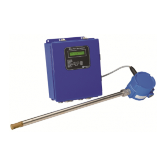
® *USPNs 5,485,754; 5,752,411 The RheoVac air in-leak monitor system consists of multiple sensors configured in a single probe head and an electronic signal conditioner and digital signal processor (DSP) unit. The sensing probe is installed in the vacuum line between the condenser and the exhauster. The RheoVac monitor is superior to all other methods in that it makes no assumptions about the dynamic condenser and vacuum line ®... -
Page 4: Principle Of Operation
1.2 PRINCIPLE OF OPERATION The principal features of the RheoVac monitor are shown in Figure 1. At the heart of the RheoVac monitor is the Rheotherm flow transducer which uses the same patented thermal sensing technique employed in all precision flow instruments manufactured by Intek. Two temperature sensor probes are used —... -
Page 5: Section 2 - Installation
Keep moisture out of the enclosures — once all service connections are made, make sure the enclosure lids are tightly closed and all gaskets are in place. Seal conduit lines at the instrument. SECTION 2 — INSTALLATION Figure 2 RheoVac Probe Insertion Recommendation - 3 -... -
Page 6: Introduction
2.1 INTRODUCTION These instructions cover installation of the RheoVac monitor in its standard configuration. Additional information pertaining to your unit is covered in SECTION 6 — CUSTOM INFORMATION. Carefully read these instructions prior to installing the equipment. 2.2 RheoVac MONITOR INSTALLATION/SITE SELECTION 2.2.1... - Page 7 - 5 -...
-
Page 8: Mounting Hardware Installation
Before installing the unit, note proper flow direction. This is important to instrument operation. Check serial number. If more than one RheoVac unit has been purchased, make sure the complete serial number of the transducer matches the complete serial number of the separate electronics unit. - Page 9 Figure 5 RheoVac Electronics Enclosure - 7 -...
-
Page 10: Electrical Connections
RS-422 should be used instead of RS-232 (See Figure 4). Inspect the header pin shunt (Figure 8) at JP14 (upper board) for the proper communication type. Consult Intek if the jumper is not configured correctly. Figure 7 Input Power Select Switch... - Page 11 RheoVac TEMPERATURE [°F] NOT USED RheoVac units have ten 4-20 mA outputs. These outputs can be configured collectively for either passive or active transmitter. The units are shipped from the factory with the output jumpers in the active position; i.e. the transmitter provides the current source. Figure 8 shows the locations of the 4-20 mA select jumper, JP13 of the lower board —...
- Page 12 - 10 -...
- Page 13 A separate external power switch is recommended to shut the equipment off during outages. When the vacuum system is on-line, do not turn off power to the RheoVac monitor unless you are preparing to take the probe out of the pipe.
- Page 14 Make wiring connections. Power should be off at this time. Refer to Figure 9 for RheoVac monitor wiring detail. Make power and transducer connections first on the lower circuit board.
- Page 15 Pulled high 2.6 RheoVac SYSTEM GROUNDING The RheoVac electrical system includes the RheoVac monitor and your data collecting inputs. In general, it is good practice to use a single point grounding scheme to terminate the system output circuit to a stable reference potential. Improper grounding may cause significant data noise, or in extreme cases, damage your equipment.
- Page 16 - 14 -...
-
Page 17: Section 3 - Operation
3.3 OUTPUT SIGNALS Standard on all RheoVac instruments are one 2 x 20 alpha numeric LED backlit display, ten 4-20 mA analog outputs, one 0-15V digital status port, and one serial communication port. Each process variable is a linear, fully temperature and pressure compensated value on any of these readable outputs. -
Page 18: Ibm-Pc Software
The best way to archive RheoVac data is with a dedicated PC or DCS serial channel. However, RheoVac software allows data from the last 24 hours to be downloaded to a PC file. This data is stored internally in the RheoVac instrument. -
Page 19: Software Operation
Install the software by inserting disk 1 into an IBM-PC compatible disk drive, select that drive, and click on the “Setup” icon. A folder, C:\RHEOVAC, will be created and seven files will be copied to this folder. The two executable files are: “uninst.exe” and “RVMain95.exe”. The others are drivers and configuration files and must remain in the RheoVac folder. -
Page 20: Data Processing
“.eep” file extension. RheoVac Air In-Leak Monitor - Use this choice to plot selected data on single or dual charts. This application can also be used to acquire data continuously into your computer system. The screen shown on page 20 appears when this choice is selected. -
Page 21: Custom Software
3.5 CUSTOM SOFTWA RE Custom software may be developed by the user to receive and archive RheoVac data into a computer system. The electronics has a serial data protocol of 9600 baud, no parity check, eight data bits and one stop bit (i.e., 9600,N,8,1). - Page 22 Figure 12 RheoVac Air In-leak Monitor IBM PC Display Menu for Plotting & Charting Data - 20 -...
-
Page 23: Section 4 - Maintenance
4.2 CALIBRATION The RheoVac air in-leak instrument is calibrated at the factory in a calibration system which replicates the condenser and vacuum line environment. The system is designed to calibrate the temperature, pressure, water vapor relative saturation and flow sensor under the gaseous fluid conditions found within the power plant vacuum line. - Page 24 TABLE VI. Trouble Shooting Guide OBSERVATION PROBA BLE CAUSE ACTION 1. Shorted cable connection 1. Check for short in cable due to moisture 'GENERAL FAU LT' or corrosion 'MODE 0' 2. Damaged flow sensor 2. * Contact factory 1. Improper cable hookup 1.
- Page 25 When using the RheoVac software on a PC, the software may give you a “Communication Error.” Use the following table to determine the source of this message and appropriate action. TABLE VI. Trouble Shooting Guide (software com munication erro rs)
- Page 26 TABLE VII. Field Check Readings JP4WIRE TRANSDUCER CABLE / WIRE EXPECTED RECORDED LABEL† VOLT AGE [V dc] VOLT AGE [V dc] SIGNAL DEFINITION Flow sensor common voltage sense < 1.0V Flow sensor current return 0.000V Flow sensor heated RTD voltage sense Range: 5 to 40mV Flow sensor heated RTD current source Range: .2 to .4V...
-
Page 27: Section 5 - Customer Service
QUESTIONS ON NEW EQUIPMENT For a new RheoVac Monitor application or any liquid or gas flow measurement need, contact the Intek technical sales department at the above phone/fax numbers. Our staff will be pleased to answer all questions and provide quotations. -
Page 28: Section 6 - Custom Information
SECTION 6 — CUSTOM INFORM ATION UNIT IDENTIFICATION Model no.: Serial no.: Customer identification: CONFIGURATION The marked (X) items denote the configuration of this unit, as originally shipped from the factory. Pipe Connection: Hot tap with 1½" MNPT connection Other Input Power: 115 Vac, 50/60 Hz 230 Vac, 50/60 Hz (switch)
Need help?
Do you have a question about the RheoVac and is the answer not in the manual?
Questions and answers