
Related Manuals for Benninca SAM

Summary of Contents for Benninca SAM
- Page 1 L854200333 09/2022 rev 1 UNIONE NAZIONALE COSTRUTTORI AUTOMATISMI PER CANCELLI, PORTE SERRANDE ED AFFINI...
- Page 3 37mm 37mm α ° A (mm) B (mm) C (mm) D (mm) 90° 90° 90° 90° 90° 90° 90° 90° 90° 120° 110° 100° 110° 100° 105°...
- Page 4 SAM.24 SAM.24 SAM.E24 SAM.E24 CP.SAM SAM.E24...
- Page 5 4xM10 max 4xM10 max 30 max. 30 max. 38,5 38,5 78,5 MIN.140 mm ∅ 8mm max.
- Page 7 SAM.24 (M2) 115-230V 50/60Hz CP.SAM 2x12V Battery (Optional) ESA:on ESA:off STAND-BY ���� ���� ���� ���� EXP.1 ���� ���� ���� LAMP LOCK AUX1 EXP.2 500 mA ENC.1 ENC.2 N.C.
- Page 8 MINV:OFF MINV:ON AUX1:0004 tst3:on RF.+ SUN PANEL SC-RF J1 Close DEFAULT 12/24 J1 Open BZ-W1-W2 CLOSE J2 DAS N.C. N.C. 12-24 Close LED 2 OPEN DAS 8K2 CH1 CH2 12/24V J2 DAS Open DAS N.C. USED...
- Page 9 AUX 1 500 mA PHOTOTEST - PHOT OP AUX1:0000 AUX1:0000 AUX1:0000 ���� AUX1 500 mA AUX1 PHOTO PHOTO PHOTO ���� AUX1:0003 AUX1:0003 AUX1:0004 24Vdc Max 500 mA LIGHT WARNING! tst1:on tst1:on tst1:on NO LED LAMP! II° CH RADIO AUX1:0001 AUX1:0001 AUX1:0001 24Vac 24Vac...
- Page 10 Display OFF Power ON Firmware Ver. (3s) v1. 0 0 8888 Diagnostic tped spd1 ibca spd2 sld1 PREL sld2 tdmo ltca tdmc tsm1 MBLK tsm2 tst1 pm01 tst2 pmc1 tst3 Pmo2 phcl PMC2 imot pso1 minv psc1 aopf pso2 psc2 blco blcc t2ch...
- Page 11 RADI PUSH PUSH PUSH STOP PUSH n tx PUSH 0025 PUSH Nman 0012 3456 MACI 2 Cycle AUTO PUSH OPEN/CLOSE RE-ENTER CODE 0000 9000 9C5a conf CODE Display OFF Legenda Premere il tasto (-) / Press key (-) / Die Taste (-) drücken Appuyez sur la touche (-) / Presionar la tecla (-) / Wcisnąć...
- Page 12 AVVERTENZE E’ vietato l’utilizzo del prodotto per scopi o con modalità non previste nel presente manuale. Usi non corretti possono essere causa di danni al prodotto e mettere in pericolo persone e cose. Si declina ogni responsabilità dall’inosservanza della buona tecnica nella costruzione dei cancelli, nonché...
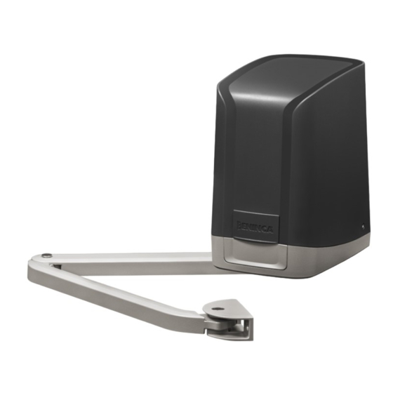
- Page 13 Automazione per la motorizzazione di ante dove gli ingombri fisici, pilastri o colonne di grandi dimensioni pregiudicano l’uso di attuatori tradizionali. SAM è dotato di braccio articolato che consente movimenti regolari e silenziosi, è di facile applicazione e, con il suo gradevole design, è in grado di soddisfare le aspettative più esigenti.
- Page 14 Rispettate la quota minima 140 mm indicata per evitare di installare il motoriduttore troppo vicino al suolo. Predisponete la canaletta per il passaggio dei cavi. il motoriduttore SAM è dotato di un pratico e innovativo passacavo in gomma per il passaggio dei cavi di collegamento.
- Page 15 - Richiudere lo sportellino scorrevole L. REGOLAZIONE FERMI ARRESTI MECCANICI - FIG.11 Entrambi i motoriduttori SAM sono forniti di un fermo meccanico regolabile, da installare come indicato in Fig. 11 per arrestare l'anta nella posizione di apertura desiderata. Si consiglia l'installazione dell'arresto meccanico di chiusura a terra, nel caso non fosse possibile è disponibile un fermo aggiuntivo (SAM.STOP) da utilizzare per arrestare anche il movimento di chiusura.
- Page 16 6) Mediante la logica MINV, selezionare il motore che deve iniziare la manovra per primo in apertura, vedi Fig.14. 7) Eseguire una procedura di autoset (vedi menu AUTOSET). L'impostazione di fabbrica prevede l'installazione del motore con centrale (SAM.E24) sull'anta di destra (come da Fig.13) con anta destra che parte per prima (Logica MINV:OFF)
- Page 17 3) Selezionare il tipo di motore utilizzato: ENC Motori con Encoder standard Motori con finecorsa elettromeccanici (Non utilizzabile su motoriduttori SAM). NLSU Motori senza finecorsa ed encoder (funzionamento a tempo automaticamente calcolato tra i fermi meccanici tramite rilevazio- ne amperometrica) 4) Premere OK per dare inizio alla fase di autoset.
- Page 18 Tempo ritardo chiusura Mot.1 tdmc 0-40-(3s) Regola il tempo di ritardo in chiusura del motore 1 rispetto al motore 2 Regola la fase di rallentamento in apertura e chiusura del motore M1. tsm1 1-99 (20%) Valore espresso in percentuale sull’intera corsa. Regola la fase di rallentamento in apertura e chiusura del motore M2.
- Page 19 Configura la modalità di funzionamento dell’Uscita AUX2: 0: uscita SCA (default) 1: uscita 2ch radio 2: uscita luce di cortesia (in base al tempo impostato dal parametro TLS). Vedi Fig.17 3: uscita luce di zona (sempre attiva con motore in movimento e durante il conteggio del TCA).
- Page 20 2s in direzione opposta per facilitare lo sgancio dell’elettroserratura. Off: Funzione disabilitata. Abilita o disabilita la funzione di blocco in apertura. blco On: Funzione blocco abilitato. Non utilizzare su motoriduttori SAM. (OFF) Off: Funzione blocco disabilitato. Abilita o disabilita la funzione di blocco in chiusura.
- Page 21 RADIO (RAD) MENU FUNZIONE Selezionando questa funzione la ricevente si pone in attesa (Push) di un codice trasmettitore da assegnare alla funzione passo-passo. Premere il tasto del trasmettitore che si intende assegnare a questa funzione. Se il codice è valido, viene memorizzato e viene visualizzato il messaggio OK Selezionando questa funzione la ricevente si pone in attesa (Push) di un codice trasmettitore da assegnare al secondo canale radio.
- Page 22 BATTERIA DI EMERGENZA La centrale CP.SAM comprende la scheda di alimentazione predisposta al collegamento in serie di due batterie 12V 2,1Ah DA.BT2 (opzionali) che consentono il funzionamento dell’automazione anche nel caso di temporanea assenza dell’alimentazione di rete.
- Page 23 MESSAGGI DI ERRORE Di seguito sono elencati alcuni messaggi che vengono visualizzati dal display in caso di anomalie di funzionamento: Amp1 Errore ostacolo motore 1/antischiacciamento Verificare presenza di ostacoli sulla corsa dell’anta motore 1 Amp2 Errore ostacolo motore 2/antischiacciamento Verificare presenza di ostacoli sulla corsa dell’anta motore 2 Verificare il corretto collegamento dell’encoder del motore 1 alla centra- ENC1 Errore encoder 1/rilevamento ostacolo...
- Page 24 WARNING The product shall not be used for purposes or in ways other than those for which the product is intended for and as described in this manual. Incorrect uses can damage the product and cause injuries and damages. The company shall not be deemed responsible for the non-compliance with a good manufacture technique of gates as well as for any deformation, which might occur during use.
- Page 25 Automation for the motorisation of gates where physical size, pillars or columns with large dimensions prejudice use of traditional actuators. SAM is equipped with an articulated arm that allows regular and silent movements. It is easily applied and, with its pleasant design, can meet the most demanding expectations.
- Page 26 - Close the sliding hatch L. ADJUSTMENT MECHANICAL STOPS - FIG.11 Both the SAM gearmotors are supplied with an adjustable mechanical stop, to install as indicated in Fig. 11 to stop the gate in the desired opening position. You are advised to install the mechanical stop on ground closure, if this is not possible an additional stop (SAM.STOP) is available to...
- Page 27 Pass the adequately channelled cables through the cable gland prepared in rubber P. For connection of the SAM.24 motor to the control panel, the section of the cable must meet the values indicated below: Distance between the SAM.24 motor and CP.SAM control panel...
- Page 28 6) Using MINV logic, select the motor which must start to move first in opening, see Fig.14. 7) Execute an autoreset procedure (see AUTOSET menu). The default setting includes installation of the motor with the control panel (SAM.E24) on the right gate (as in the Fig.13) with the right gate that starts first (MINV:OFF logic)
- Page 29 3) Select the type of motor used: ENC Motors with standard encoder Motors with electromechanical limit switch (Cannot be used on SAM gearmotors). NLSU Motors without limit switch and encoder (timed function automatically calculated between the mechanical stops via ampero- metric detection) 4) Press OK to start the autoset phase.
- Page 30 Adjusts the slowdown phase in the opening and closing of the M1 motor. tsm1 1-99 (20%) Value expressed as a percentage on the entire run. Adjusts the slowdown phase in the opening and closing of the M2 motor. tsm2 1-99 (20%) Value expressed as a percentage on the entire run.
- Page 31 * ATTENTION: FURTHER SETTING OF THESE PARAMETERS CAN BE DANGEROUS. COMPLY WITH LEGISLATION IN FORCE! With the motors without a limit switch and/or encoder, adjust the sensitivity of the sensor that causes stoppage during the slowdown phase. ** 1: minimum force/torque - 99: maximum force/torque. The control panel avails of two anti-crushing devices: the amperometric sensor (adjusted by parameters PMO1/2-PMC1/2-PSO1/2- PSC1/2) and the encoder (adjusted by the SEAV and SEAR parameters).
- Page 32 Off: Function disabled. Enables or disables the block in opening function. blco On: Block function enabled. Do not use on SAM gearmotors. (OFF) Off: Block function disabled. Enables or disables the block in closure function.
- Page 33 RADIO (RAD) MENU FUNZIONE Selecting this function, the receiver sets in standby (Push) of a transmitter code to assign to the step-step function. Press the transmitter key you intend to assign to this function. If the code is valid, it is saved and the message OK is displayed Selecting this function, the receiver sets in standby (Push) of a transmitter code to assign to the second radio channel.
- Page 34 EMERGENCY BATTERY The CP.SAM control panel includes the power supply board prepared for connection in series of two batteries 12V 2,1Ah DA.BT2 (optional) which enable operation of the automation also in the event of temporary absence of the mains power supply.
- Page 35 ERROR MESSAGES The list is displayed of some messages which are shown on the display in the event of an operating anomaly: Amp1 Motor 1 obstacle error/anti-crushing Check the presence of obstacles on the stroke of the motor gate 1 Amp2 Motor 2 obstacle error/anti-crushing Check the presence of obstacles on the stroke of the motor gate 2...
- Page 36 HINWEISE Das Produkt darf nicht für andere Zwecke oder auf andere Weise verwendet werden, als in der vorliegenden Anleitung be- schrieben. Ein ungeeigneter Gebrauch kann das Produkt beschädigen und eine Gefahr für Personen und Sachen darstellen. Wir übernehmen keinerlei Haftung für Schäden, die sich aus einer unsachgerechten Montage der Tore und aus daraus fol- genden Verformungen ergeben können.
- Page 37 Automatisierung für die Motorisierung von Türen, bei denen große Abmessungen, Pfeiler oder Säulen den Einsatz von herkömmlichen Antrieben verhindern. SAM ist mit einem Gelenkarm ausgestattet, der sanfte und geräuschlose Bewegungen ermöglicht, er ist einfach anzuwenden und erfüllt mit seinem angenehmen Design auch die anspruchsvollsten Erwartungen.
- Page 38 Die angegebene Mindesthöhe von 140 mm einhalten, damit der Getriebemotor nicht zu nahe am Boden installiert wird. Den Kabelkanal für die Durchführung der Kabel vorbereiten. Der SAM-Getriebemotor ist mit einer praktischen und innovativen Gummi- tülle für die Durchführung der Anschlusskabel ausgestattet. Eine Schere verwenden, um die für den verwendeten Kabeltyp am besten geeigneten Durchgänge zu öffnen;...
- Page 39 (SAM.STOP) erhältlich, der die Schließbewegung ebenfalls stoppt. Die Endanschläge sollten erst installiert werden, nachdem die Arme SAM.BA und SAM an der Säule befestigt worden sind. Den Hebel C mit der M10-Schraube R, der Unterlegscheibe G und der Fächerscheibe R an der Drehwelle befestigen, wie auf Abb. 11 dargestellt.
- Page 40 4) Mit der Taste, die an den Eingang PP angeschlossen ist, Fernsteuerung oder Taste <-> eine Schrittsteuerung geben. 5) Die Türen müssen sich in Öffnung bewegen. Sollte dies nicht der Fall sein, einfach die Motorlaufdrähte umkehren, indem man den MOT1-Stecker am SAM.E24 um 180° dreht und die MOT2-Drähte für den SAM.24-Motor umkehrt.
- Page 41 2) Die Taste PG drücken, um auf die Programmierung zuzugreifen, mit der Taste + die Funktion AUTO auswählen und OK drücken. 3) Die Art des verwendeten Motors wählen: ENC-Motoren mit Standard-Encoder LSU-Motoren mit elektromechanischen Endschaltern (können nicht für SAM-Getriebemotoren verwendet werden). NLSU-Motoren ohne Endschalter und Encoder (automatische Berechnung der Betriebszeit zwischen den mechanischen Anschlägen durch amperometrische Erfassung) 4) OK drücken, um die Autoset-Phase zu starten.
- Page 42 Stellt die Geschwindigkeit des Motors 2 während der Verlangsamungsphase ein. Der sld2 10-50 (25%) Wert ist angegeben in Prozent. Öffnungsverzögerungszeit Mot.2 tdmo 0-15-(2s) Stellt die Öffnungsverzögerungszeit von Motor 2 im Verhältnis zu Motor 1 ein. Schließverzögerungszeit Mot.1 tdmc 0-40-(3s) Stellt die Schließverzögerungszeit von Motor 1 im Verhältnis zu Motor 2 ein. Die Verlangsamen beim Öffnen und Schließen von Motor M1 regulieren.
- Page 43 Konfiguriert den Funktionsmodus des Ausgangs AUX2: 0: Ausgang SCA (Standard) 1: Funkausgang 2ch 2: Ausgang des Servicelichts (abhängig von der mit dem Parameter TLS eingestellten Zeit). Siehe Abb.17 3: Zonenlichtausgang (immer aktiv bei laufendem Motor und während der TCA-Zäh- lung). Siehe Abb.17 aux2 0-6 (1) 4: Fototest.
- Page 44 (OFF) zu erleichtern. Off: Funktion deaktiviert. Aktivieren oder deaktivieren der Verriegelungsfunktion beim Öffnen. blco On: Blockierfunktion aktiviert. Nicht für SAM-Getriebemotoren verwenden. (OFF) Off: Blockierfunktion deaktiviert. Aktivieren oder deaktivieren der Verriegelungsfunktion beim Schließen. blcc On: Blockierfunktion aktiviert. Nicht für SAM-Getriebemotoren verwenden.
- Page 45 Aktiviert oder deaktiviert die ferngesteuerte Erfassung der Funksender, wie in Abschnitt „Ferngesteuerte Erfassung der Sender“ angegeben. (ON) On: Ferngesteuerte Erfassung aktiviert. Off: Ferngesteuerte Erfassung deaktiviert. Aktiviert oder deaktiviert die Funktion der Energieeinsparung „ESA“. On: Wenn der Vorgang beendet ist und die Aktivierungszeit der Service-Lichter abgelaufen ist, schaltet das Steuergerät den Zubehörausgang aus und schaltet ihn in Standby.
- Page 46 Anschlüsse korrekt wiederhergestellt sind, wird der Ausgang der Zusatzstromversorgung automatisch wieder in Betrieb genommen. NOTFALLBATTERIE Die Steuereinheit CP.SAM enthält eine Stromversorgungsplatine, die für den Anschluss von zwei 12V 2,1Ah DA.BT2-Batterien (optional) vorgesehen ist, die den Betrieb der Automatisierung auch bei einem vorübergehenden Stromausfall ermöglichen.
- Page 47 Während dem normalen Netzbetrieb sorgt die Platine CP.SAM für das Aufladen der Batterien. Der maximale Ladestrom beträgt 1A, der durchschnittliche Ladestrom beträgt 300mA. (Beachten Sie die Polarität). Für den Einbau der Batterie lesen Sie bitte die mit dem SM.CB-Bausatz gelieferte Anleitung.
- Page 48 AVERTISSEMENTS Il est interdit d’utiliser ce produit pour l’utilisation du produit ou avec des finalités ou modalités non prévues par le présent manuel. Toute autre utilisation pourrait compromettre l’intégrité du produit et présenter un danger pour les personnes ou pour les biens. Le fabricant décline toute responsabilité...
- Page 49 Opérateur pour la motorisation de portail où les dimensions physiques, les piliers ou les grandes colonnes empêchent l’utilisation d’opé- rateurs linéaires. SAM est équipé d’un bras articulé qui permet des mouvements fluides et silencieux, très compact et facile à installer avec son design attrayant, il répond aux attentes les plus exigeantes du marché.
- Page 50 Respectez la hauteur minimale de 140 mm indiquée pour éviter d’installer l’opérateur trop près du sol. Prévoyez le passage de câbles. L’opérateur SAM est équipé d’un presse-étoupe en caoutchouc pratique et innovant pour le passage des câbles de branchement. Utilisez des ciseaux pour ouvrir les passages les plus appropriés au type de câble utilisé ; les diamètres des câbles sont indiqués en mm sur le presse-étoupe.
- Page 51 - Fermez la trappe à coulisse L. RÉGLAGE DES BUTÉES MÉCANIQUES - FIG. 11 Les deux opérateurs SAM sont équipés d’une butée mécanique à l’ouverture réglable, à installer comme indiqué sur la Fig. 11 pour arrêter le vantail dans la position d’ouverture souhaitée.
- Page 52 4) Donnez une commande pas à pas par un bouton connecté à l’entrée PP, un émetteur ou le bouton <- > 5) Les portes doivent bouger à l’ouverture Si ce n’est pas le cas, inversez les fils d’alimentation du moteur en tournant le connecteur MOT1 du SAM.E24 de 180° et en inversant les fils MOT2 du moteur SAM.24.
- Page 53 3) Sélectionnez le type de moteur utilisé : ENC Moteurs avec encodeur standard Moteurs avec fin de course électromécaniques (ne pas utiliser avec les opérateurs SAM) NLSU Moteurs sans fin de course électromécaniques et sans encodeur (fonctionnement en temps calculé automatiquement entre les arrêts mécaniques par détection ampérométrique)
- Page 54 Retard à l’ouverture Mot.2 tdmo 0-15-(2s) Règle le retard à l’ouverture du moteur 2 par rapport au moteur 1. Retard à la fermeture Mot.1 tdmc 0-40-(3s) Règle le retard à la fermeture du moteur 1 par rapport au moteur 2. Règle la phase de ralentissement en ouverture et fermeture du moteur M1. tsm1 1-99 (20%) Valeur exprimée en pourcentage sur toute la course.
- Page 55 Configure le mode de fonctionnement de la sortie AUX2 : 0 : sortie SCA (par défaut) - Témoin portail ouvert 1 : sortie radio 2ch 2 : sortie éclairage de zone (en fonction de la durée définie par le paramètre TLS). Voir Fig. 17 3 : sortie éclairage de zone (toujours active avec le moteur en mouvement et pendant le TCA).
- Page 56 Off : Fonction désactivée. Active ou désactive la fonction de blocage à l’ouverture. blco On : Fonction de blocage activée. Ne pas utiliser sur les motoréducteurs SAM. (OFF) Off : Fonction de blocage désactivée. Active ou désactive la fonction de blocage à la fermeture.
- Page 57 Active ou désactive la fonction d’économie d’énergie « ESA ». On : Une fois la manœuvre terminée et le temps d’activation de l’éclairage de zone écoulé, la centrale de commande coupe l’alimentation des accessoire et se met en modalité veille. L’alimentation des accessoires reste toutefois active uniquement pendant le temps (ON) nécessaire, si les réglages des paramètres AUX1/AUX2 l’exigent.
- Page 58 BATTERIES DE SECOURS La centrale de commande CP.SAM comprend le chargeur pour 2 batteries de secours branchées en série de 12V 2.1Ah DA.BT2 (en option) qui permettent à l’opérateur de fonctionner même en cas de panne de courant temporaire.
- Page 59 Pendant le fonctionnement normal, la carte CP.SAM recharge les batteries. Le courant de charge maximal est de 1A, le courant de charge moyen est de 300 mA. (respectez la polarité). Pour l’installation des batteries, veuillez-vous référer aux instructions fournies avec le kit SM.CB.
- Page 60 ADVERTENCIAS Está prohibido utilizar el producto para finalidades o con modalidades no previstas en el presente manual. Usos incorrectos pueden causar daños al producto y poner en peligro personas y cosas. Se rehúsa cualquier responsabilidad en caso de incumplimiento de la buena técnica en la construcción de las cancelas, así como en cuanto a las deformaciones que pudieran producirse durante el uso.
- Page 61 Automatización para la motorización de puertas donde las dimensiones físicas, los grandes pilares o las columnas impiden el uso de actuadores tradicionales. SAM está equipado con un brazo articulado que permite movimientos suaves y silenciosos, es fácil de aplicar y, con su atractivo diseño, es capaz de satisfacer las expectativas más exigentes.
- Page 62 Respete la altura mínima de 140 mm indicada para evitar instalar el motorreductor demasiado cerca del suelo. El motorreductor SAM está equipado con un práctico e innovador canal de goma para el paso de los cables de conexión. Utilice unas tijeras para abrir los pasos más adecuados para el tipo de cable utilizado;...
- Page 63 Se aconseja instalar el tope mecánico en el suelo, si esto no es posible, se dispone de un tope adicional (SAM.STOP) que se utiliza para detener también el movimiento de cierre.
- Page 64 7) Realice un procedimiento de autoset (véase el menú AUTOSET). El ajuste de fábrica prevé la instalación del motor con la unidad de control (SAM.E24) en la puerta derecha (como se muestra en la Fig.13) con el arranque de la puerta derecha en primer lugar (Lógica MINV:OFF).
- Page 65 3) Seleccione el tipo de motor utilizado: Motores ENC con encoder estándar Motores LSU con finales de carrera electromecánicos (no pueden utilizarse en motorreductores SAM). Motores NLSU sin finales de carrera y encoderes (operación de tiempo calculada automáticamente entre paradas mecánicas me- diante detección amperométrica)
- Page 66 Regula la fase de paro suave en apertura y cierre del motor M2. tsm2 1-99 (20%) Valor expresado en porcentaje sobre la carrera completa. Ajusta el umbral de intervención del dispositivo anti aplastamiento* (sensor pmo1 1-99-(30%)** amperométrico) durante la fase de apertura a velocidad normal - Motor 1 Ajusta el umbral de intervención del dispositivo anti aplastamiento* (sensor pmc1 1-99-(30%)**...
- Page 67 Configura la modalidad de funcionamiento de la salida AUX2: 0: salida SCA (por defecto) 1: salida 2ch radio 2: salida luz de cortesía (dependiendo del tiempo establecido por el parámetro TLS). Véase Fig.17. 3: salida luz de zona (siempre activa con el motor en movimiento y durante el recuento aux2 del TCA).
- Page 68 2s en sentido contrario para facilitar el desbloqueo de la cerradura eléctrica. Off: Función deshabilitada. Habilita o deshabilita la función de bloqueo en apertura. blco On: Función bloqueo habilitado. No utilizar en motorreductores SAM. (OFF) Off: Función bloqueo deshabilitado. Habilita o deshabilita la función de bloqueo en cierre.
- Page 69 Activa o desactiva la funcionalidad de ahorro energético “ESA”. On: Una vez finalizada la maniobra y transcurrido el tiempo de activación de la luz de servicio, la centralita retira la alimentación de la salida de accesorios y pasa al modo de espera.
- Page 70 BATERÍA DE EMERGENCIA La unidad de control CP.SAM incluye la tarjeta de alimentación diseñada para la conexión en serie de dos baterías DA.BT2 de 12V y 2,1Ah (opcional) que permiten el funcionamiento de la automatización incluso en caso de corte de corriente temporal.
- Page 71 DIAGNÓSTICO Cada entrada está asociada a un segmento de la pantalla que se ilumina cuando se activa, SWO1 SWO2 SWC1 SWC2 según el siguiente esquema. P.P. OPEN CLOSE Las entradas N.C. están representadas por los segmentos verticales. Las entradas de N.O. están representadas por los segmentos horizontales. La centralita muestra ael mensaje AMP1 o AMP2 en caso de intervención del sensor am- perométrico anti aplastamiento.
- Page 72 OSTRZEŻENIA Zabrania się używania produktu do celów i w sposób inny niż przewidziane w niniejszym podręczniku. Nieprawidłowe uży- wanie może spowodować uszkodzenie produktu i stanowić zagrożenie dla osób i rzeczy. Nie bierze się na siebie żadnej odpowiedzialności za nieprzestrzeganie reguł dobrej techniki budowlanej przy realizacji bram, a także w przypadku odkształceń, które mogłyby powstać...
- Page 73 Automatyka do napędu bram skrzydłowych, gdzie wymiary gabarytowe oraz dużych rozmiarów filary i podpory nie pozwalają na za- stosowanie tradycyjnych siłowników. Napęd SAM zawiera ramię przegubowe umożliwiające regularne i bezhałasowe przesuwanie się, ma estetyczny wygląd, jest prosty w obsłudze i jest w stanie zaspokoić najbardziej wygórowane oczekiwania.
- Page 74 Zwrócić uwagę na wskazaną minimalną wysokość 140 mm, aby uniknąć montażu siłownika zbyt blisko podłoża. Przygotować kanał do przeprowadzenia kabli. Siłownik SAM jest wyposażony w praktyczny i innowacyjny przepust gumowy do prze- prowadzania kabli połączeniowych. Za pomocą nożyczek wykonać otwory dostosowane do rodzaju użytego kabla. Na przepuście kablowym wskazane są...
- Page 75 Zamocować dźwignię C do wału obrotowego, tak jak to pokazano na Rys. 11, za pomocą śruby M10 R, podkładki płaskiej G i podkładki ząbkowanej R. Ważne jest, aby krzywka była zamontowana skierowana w tę samą stroną co proste ramię, tak jak to pokazano na rysunku. W ten sposób możliwe będzie zamocowanie mechanicznego ogranicznika w prawidłowym położeniu.
- Page 76 4) Uruchomić tryb krokowy naciśnięciem przycisku podłączonego do wejścia PP, ze sterowania radiowego lub przyciskiem <->. 5) Skrzydła bramy powinny wykonać ruch otwierania. Jeśli tak się nie stanie, należy odwrócić przewody silnika, obracając złącze MOT1 na siłowniku SAM.E24 o 180° i odwraca- jąc przewody MOT2 dla silnika SAM.24.
- Page 77 3) Wybrać typ użytego silnika: ENC Standardowe silniki z enkoderem. Silniki z elektromechanicznymi wyłącznikami krańcowymi (nie nadające się do zastosowania w siłownikach SAM). NLSU Silniki bez wyłączników krańcowych i enkodera (działanie czasowe automatycznie obliczane między ogranicznikami mecha- nicznymi przez czujnik amperometryczny).
- Page 78 Reguluje spowalnianie podczas otwierania i zamykania przez silnik M2. tsm2 1-99 (20%) Wartość jest wyrażona procentowo w odniesieniu do całkowitego skoku bramy. Reguluje próg zadziałania urządzenia zabezpieczającego przed przygnieceniem* pmo1 1-99-(30%)** (czujnik amperometryczny) w trakcie otwierania z normalną prędkością - Silnik 1 Reguluje próg zadziałania urządzenia zabezpieczającego przed przygnieceniem* pmc1 1-99-(30%)**...
- Page 79 Konfiguruje tryb funkcjonowania wyjścia AUX2: 0: wyjście SCA (domyślnie) 1: wyjście 2ch radio 2: wyjście światła roboczego (na podstawie czasu ustawionego dla parametru TLS). Patrz Rys.17 3: wyjście światła strefowego (aktywne cały czas z silnikiem w ruchu i w trakcie odli- czania parametru TCA).
- Page 80 2 s, aby ułatwić odblokowanie zamka elektrycznego. Off: Funkcja wyłączona. Włącza lub wyłącza funkcję blokady w trakcie otwierania. blco On: Funkcja blokady włączona. Nie używać jej dla siłowników SAM. (OFF) Off: Funkcja blokady wyłączona. Włącza lub wyłącza funkcję blokady w trakcie zamykania.
- Page 81 Włącza lub wyłącza funkcję energooszczędności „ESA”. On: Po zakończeniu manewru i po upływie czasu aktywacji światła roboczego, centrala odcina zasilanie na wyjściu akcesoriów, ustawiając się w trybie stand-by. Zasilanie akcesoriów pozostaje włączone tylko przez niezbędny czas, jeśli wymagają tego (ON) ustawienia parametrów AUX1/AUX2.
- Page 82 BATERIA BUFOROWA Centrala CP.SAM jest wyposażona w płytę zasilania do zarządzania szeregowego dwiema bateriami 12V 2,1 Ah DA.BT2 (opcjonalnymi) umożliwiającymi działanie napędu, również w przypadku chwilowego braku zasilania sieciowego. Podczas normalnego działania sieci, płyta centrali CP.SAM gwarantuje ładowanie baterii.
- Page 83 Maksymalny prąd ładowania wynosi 1A, średni prąd ładowania wynosi 300mA. (przestrzegać biegunowości). Informacje dotyczące montażu baterii można znaleźć w instrukcji obsługi załączonej do zestawu SM.CB. DIAGNOSTYKA Dla każdego wejścia jest przypisany segment wyświetlacza, który w przypadku aktywacji SWO1 SWO2 SWC1 SWC2 wejścia podświetla się...
- Page 84 ISTRUZIONI PER L’UTILIZZATORE NORME DI SICUREZZA • Conservare con cura il registro di manutenzione che l'in- stallatore ha l'obbligo di consegnarvi, rispettare il piano di • Non sostare nella zona di movimento dell'anta. manutenzione previsto. • Non lasciare che i bambini giochino con i comandi o in prossi- •...
- Page 85 USER’S HANDBOOK SAFETY MEASURES • The operator is maintenance free but it is necessary to check periodically if the safety devices and the other components of • Do not stand within the gate movement area. the automation system work properly. Wear and tear of some •...
- Page 86 HANDBUCH FÜR DEN VERBRAUCHER SICHERHEITSVORSCHRIFTEN • Kontrollieren Sie regelmäßig die Effizienz der Schutzvorrich- tungen und der anderen Anlagenteile, die durch Verschleiß • Sich nicht im Bewegungsbereich des Flügels aufhalten. eine Gefahr darstellen können. • Nicht zulassen dass Kinder mit den Steuerungen oder in der •...
- Page 87 MANUEL D’INSTRUCTIONS POUR L’UTILISATEUR NORMES DE SÉCURITÉ • L’actuateur ne demande pas de manutention ordinaire mais il faut verifier periodiquement l’efficience des dispositifs de sécurité et • Ne pas stationner dans la zone de mouvement du vantail. les autres parties de l’installation qui puissent créer dangers à •...
- Page 88 MANUAL DE INSTRUCCIONES PARA EL USUARIO NORMAS DE SEGURIDAD • El operador no requiere mantenimiento habitual, no obstante es necesario verificar periódicamente la eficiencia de los dispositivos • No pararse en la zona de movimiento de la hoja. de seguridad y las otras partes de la instalación que pudiesen •...
- Page 89 KSIĄŻECZKA Z INSTRUKCJAMI DLA UŻYTKOWNIKA NORMY BEZPIECZEŃSTWA • Przechowywać dziennik konserwacji obowiązkowo pozo- • Nie przestawać w obszarze przesuwu skrzydła bramy. stawiony użytkownikowi przez instalatora. Przestrzegać wskazanego planu konserwacji. • Nie pozwolić, żeby dzieci bawiły się sterowaniem bramy lub ogólnie w pobliżu skrzydła. •...
- Page 90 Declare that the DOC is issued under our sole responsibility and belongs to the following product: Dichiara che il documento è rilasciato sotto la propria responsabilità e appartiene al seguente prodotto: Model/Product: SAM.24 / SAM.E24 Modello/Tipo: SAM.24 / SAM.E24 Type:...
- Page 91 Declara que el documento ha sido emitido bajo la propia responsabilidad y pertenece al siguiente producto: Oświadcza, że dokument został wydany na własną odpowiedzialność i dotyczy produktu: Modelo/Tipo: Model/Typ: SAM.24 / SAM.E24 SAM.24 / SAM.E24 Tipo de producto: Rodzaj produktu: Motorreductor electromecánico 24Vdc para portones batientes...
- Page 92 AUTOMATISMI BENINCÀ SpA - Via Capitello, 45 - 36066 Sandrigo (VI) - Tel. 0444 751030 r.a. - Fax 0444 759728...
Need help?
Do you have a question about the SAM and is the answer not in the manual?
Questions and answers