
Related Manuals for Lowrance LCF-1440


Summary of Contents for Lowrance LCF-1440
- Page 1 Pub. 988-0151-071 www.lowrance.com LCF-1440 LCD Flasher Sonar Installation and Operation Instructions...
- Page 2 Lowrance Electronics, Inc. Marine-Tex is a trademark of Illinois Tool Works Inc. Lowrance Electronics may find it necessary to change or end our policies, regulations, and special offers at any time. We reserve the right to do so without notice. All features and specifications subject to change without notice.
-
Page 3: Table Of Contents
Introduction ... 1 Capabilities and Specifications: LCF-1440... 1 Installation Instructions... 2 Preparation ... 2 Recommended Tools and Supplies ... 2 Mounting the Unit ... 2 Speaker... 3 Power Connections... 4 Transducer ... 4 Operation ... 5 Keyboard Basics... 5 Memory... 5 Menus ... - Page 4 Notes...
-
Page 5: Introduction
To get started with your Lowrance sonar, first read the installation section. It contains instructions for mounting the sonar unit. If necessary, also consult the accompanying transducer installation instructions. -
Page 6: Installation Instructions
To mount the LCF-1440 in the dash, first make sure there is sufficient clearance behind the panel in the desired location. Also, see that there is adequate room to connect power and transducer cables. -
Page 7: Speaker
(side view) Speaker cable Connect white wire to "Lights" switch on your boat's instrument panel. Power/trans- ducer cable Pod transducer LCF-1440 system components installed, including power connections. Black wires Speaker 2-amp fuse Red wires Black wire 12 volt battery temp... -
Page 8: Power Connections
(part 988-0147-581 for Skimmer-type transducers, part 988-0147-721 for pod-type). Lowrance sells many different styles of transducers. If you do not have a transducer installed, consult your local boat dealer or the Lowrance service center for assistance selecting the proper transducer for your boat. -
Page 9: Operation
Menus change depending on the mode the unit is in. Messages may appear in menu boxes or new menus can appear, depending on previous selections. Operation The LCF-1440 Keyboard. – Use these keys to adjust virtually every – Use this key to turn the unit on and off. -
Page 10: Display - Opening Screen
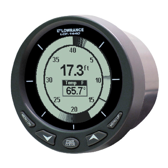
ARROW seconds. If you don't want to wait, press When the sonar unit is first turned on and the backlight menu disappears, the display screen shows the Flasher page. An image like the one below will appear on the screen. A circular dial shows all returning echoes at a high screen refresh rate. -
Page 11: Range
If your transducer has a built-in temp sensor connected, the water temperature will appear inside the circle. This temperature display can be turned on and off. See the later entry on Temperature for off and on instructions RANGE When turned on, the unit automatically adjusts the depth range according to water conditions. - Page 12 bottom and make minor adjustments to the sensitivity level, with a bias toward the setting you selected. Adjusting sensitivity in Manual Sensitivity Mode is similar to driving a car without cruise control — you have complete manual control of the car's speed.
-
Page 13: Grayline
Since Grayline shows the difference between strong and weak signals, adjusting the sensitivity may also require a different Grayline level. The level chosen by the sonar unit at power on is usually adequate for most conditions. Experiment with your unit to find the Grayline setting that's best for you. -
Page 14: Depth Alarms
Depth Alarms The depth alarms are triggered only by the bottom signal. No other echoes will activate these alarms. The depth alarms consist of a shallow and a deep alarm. The shallow alarm sounds an alarm tone when the bottom goes shallower than the alarm's setting. The deep alarm sounds a tone when the bottom goes deeper than its setting. -
Page 15: Noise Reject And Asp (Advanced Signal Processing)
ASP is an effective tool in combating noise. In sonar terms, noise is any undesired signal. It is caused by electrical and mechanical sources such as bilge pumps, engine ignition systems and wiring, air bubbles passing over the face of the transducer, even vibration from the engine. -
Page 16: Backlights
BACKLIGHTS The display is backlit for night use. To turn the backlight on or off, press appears. Press to turn it off. ARROW DISPLAY CONTRAST The unit’s display contrast is adjustable to suit different lighting conditions. This will help you see the screen from different angles or at various times of the day. - Page 17 LOWRANCE ELECTRONICS FULL ONE-YEAR WARRANTY "We," "our," or "us" refers to LOWRANCE ELECTRONICS, INC., the manufacturer of this product. "You" or "your" refers to the first person who purchases this product as a consumer item for personal, family or household use.
-
Page 18: How To Obtain Service
…in the USA: We back your investment in quality products with quick, expert service and genuine Lowrance parts. If you're in the United States and you have technical, return or repair questions, please contact the Factory Customer Service Department. Before any product can be returned, you must call customer service to determine if a return is necessary. -
Page 19: Accessory Ordering Information For All Countries
To locate a Lowrance dealer near you, visit our web site, www.lowrance.com and look for the Dealer Locator. Or, you can consult your telephone directory for listings. -
Page 20: Visit Our Website
Visit our web site: Lowrance Pub. 988-0151-071 © Copyright 2003 All Rights Reserved Printed in USA 041703 Lowrance Electronics, Inc.
Need help?
Do you have a question about the LCF-1440 and is the answer not in the manual?
Questions and answers