
Related Manuals for Ferndale Safety TC

Summary of Contents for Ferndale Safety TC
- Page 1 Toll-Free: 855-326-1243 https://www.ferndalesafety.com MODEL TC CHIP SHIELD INSTALLATION GUIDE Page 1 of 5...
- Page 2 855-326-1243. IDENTIFICATION OF COMPONENTS Before installation, please make sure you have all components. You should have for TC-1, TC-2, & TC-3 models: One (1) shield assembly One (1) mounting posts For TC-4, TC-5, & TC-6 models: One (1) Chip Shield Assembly The shield assembly gets installed onto the mounting post.
- Page 3 INSTALLATION (Cont.) (TC-1, TC-2, TC-3 Only) Tighten this screw to lock the tube in place. The tube can be moved up or down for adjustment in height. Figure 3: View of the mounting bracket from the back of a lathe.
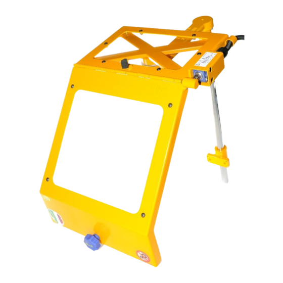
- Page 4 INSTALLATION (TC-4, TC-5, TC-6 Only) We have made the TC-4, TC-5, and TC-6 models to install on the front of a lathe tool post or carriage on huge lathes. These shields do not require any additional assembly to use. Use two or more ¼”-20 x 1” bolts to secure the mounting bracket to a flat surface.
- Page 5 ELECTRICAL CONNECTION (TC-1, TC-2, TC-3 Only) NOTE: THIS APPLIES ONLY TO CHIP SHIELDS WITH THE SAFETY INTERLOCK SWITCH OPTION. Contact Rating: 3A @ 240VAC, 0.1A @ 240VDC Wire Color Codes and Sample Wiring Diagram: IMPORTANT: Do not connect the switch directly to the motor. The switch was not designed to handle motor loads.
Need help?
Do you have a question about the TC and is the answer not in the manual?
Questions and answers