
Related Manuals for Electrolux FC48


Summary of Contents for Electrolux FC48
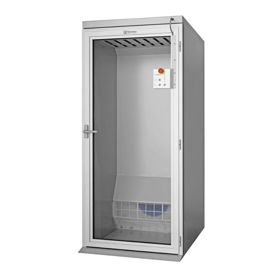
- Page 1 Installation manual Finishing cabinet FC48 Translated from french 05306004/GB 26.2019...
-
Page 3: Table Of Contents
05306004 1004 INSTALLATION Table of contents Notice Date Page MANUAL Pages/Chapters General instructions Environmental information ..................1/1 Preliminary instructions ..................1/2 Note about the A.C. power ................... 3/2 Handling/Weight Handling ........................ 1/3 Packing - Weight....................1/4 Technical characteristics Setting up dimensions................... 1/5 Technical characteristics .................. -
Page 4: Environmental Information
05306004 1004 1. General INSTALLATION instruction Notice Date Page MANUAL Environmental information Concerned by providing the end user with useful and necessary environmental information, we wish to precise : Data about energetic consumptions, wastes (atmospheric and liquid) and sound level are •... -
Page 5: Preliminary Instructions
05306004 1004 INSTALLATION 2. Preliminary instructions Notice Date Page MANUAL This machine should be installed in conformance to the health and safety regulations, and only used in a sufficiently aerated area. Check the instructions before installing or using the machine. SAFETY The mechanical and electrical installation of the machine should... - Page 6 0305 05306004 INSTALLATION 2. Preliminary instructions Notice Date Page MANUAL CAUTION In order to avoid any bending of casings, you should never climb and stand on top of the machine.
-
Page 7: Note About The A.c. Power
05306004 0305 INSTALLATION 2. Preliminary instructions Notice Date Page MANUAL Note about the A.C. power According to the EN 60204-1:1997 standard, the machine is provided for AC supplies • corresponding to the extracted caracteristics below : 4.3.2 AC supplies Voltage : Steady state voltage : from 0.9 to 1,1 of nominal voltage. -
Page 8: Handling
05306004 1004 INSTALLATION 3. Handling Notice Date Page MANUAL WARNING It is obligatory that all these operations are undertaken by handling specialists. Lifting with a fork-lift truck The machine is delivered secured on a transport pallet. D1188 Lifting with handling straps Lifting in that case can only be done with handling straps (minimum capacity 500 daN) which bear weight of the machine... -
Page 9: Packing - Weight
05306004 0905 INSTALLATION 4. Packing - Weight Notice Date Page MANUAL Packing Packing dimensions Size A Size B Size C 1060 1500 2200 Weight in daN Electric Steam (machine + pallet) (without boiler) (machine + pallet) (with boiler) (machine + box) (without boiler) (machine + box) (with boiler) Identification plate Adjustment label... -
Page 10: Technical Characteristics
05306004 1612 5. Technical INSTALLATION characteristics Notice Date Page MANUAL Setting up dimensions 1270 1220 1325 07100130... - Page 11 1113 05306004 5. Technical INSTALLATION characteristics Notice Date Page MANUAL Diagram no. 07100130 Electric Gas Steam Heating units External dimensions 1975 1975 1975 Height Width 1310 1310 1310 Depth 1000 1000 1000 (A) Space between the machine and a wall (according to the recommendation in standard EN 60204) Internal dimensions Inside volume litre Inside usefull width...
-
Page 12: Sound Level
05306004 1004 5. Technical INSTALLATION characteristics Notice Date Page MANUAL Sound level Airborne noise emitted by the machine (values establiqhed from measurements made on the machine at points A, B, C, (40”) D0267 Weighted sound pressure level (A) in dB (A). Finishing cabinet 70,8 74,1... -
Page 13: Unpacking
05306004 1004 6. Installation/ INSTALLATION Putting into service Notice Date Page MANUAL You should have found this instruction handbook and eight coathangers. Please refer to the handling chapter in this instruction handbook for a description of handling operations. Unpacking Release the machine from its packing. Check that no damage has been caused during transport. -
Page 14: Installation
05306004 1004 6. Installation/ INSTALLATION Putting into service Notice Date Page MANUAL Installation The installation must be done by compe- tent technicians in accordance with local codes and regulations. When there is no local code or regulation, the installation must be comply with european stan- dards applicable. -
Page 15: Gas Connection
05306004 1004 6. Installation/ INSTALLATION Putting into service Notice Date Page MANUAL Gas connection CAUTION The installation, connection and gas arrival adjustments for the machine must be done by qualified personnel only. The customer must install a filter and a manual stop valve on the supply side of the machine if NATURAL GAS is used. - Page 16 05306004 1004 6. Installation/ INSTALLATION Putting into service Notice Date Page MANUAL If the machine is connected to gas mains of 300 mbar or directly behind a gas bottle, it is vital that a pressure reducing valve be added as close as possible to the machine. 300 mbar D1140 If the gas inlet pressure (P1) is identical to the nominal pressure of the machine (P2), it is...
- Page 17 1004 05306004 6. Installation/ INSTALLATION Putting into service Notice Date Page MANUAL The machine is adjusted at the plant to be suitable for the kind of gas specified on the order. If you have to supply your machine with gas in a family different from the gas for which your machine was adjusted, proceed as follows.
- Page 18 05306004 1004 6. Installation/ INSTALLATION Putting into service Notice Date Page MANUAL IMPORTANT Adjustments should be made by qualified personnel only. Adjustement and chesking of the outlet pressure The gas outlet pressure of the electrovalve is adjusted at the factory. If you have to make another adjustment, proced as follows.
- Page 19 05306004 1114 6. Installation/ INSTALLATION Putting into service Notice Date Page MANUAL Legend of symbols used I: machine working with only one gas family machine working with two gas families 1: 1 family : caol gas or town gas (for information : not used here) 2: 2 family : natural gas family : liquef ed petroleum gas (LPG)
- Page 20 05306004 1004 6. Installation/ INSTALLATION Putting into service Notice Date Page MANUAL TABLE OF CORRESPONDENCES - Finishing cabinet FC48 Category Type Working Ø of Pressure at Heat Consumption Consum- index supply injectors injectors emission ption pressure Qn in kW Mn in...
-
Page 21: Connection Of The Ironer Evacuation System
05306004 1004 6. Installation/ INSTALLATION Putting into service Notice Date Page MANUAL Connection of the ironer evacuation systeme Fresh air inlet To allow the machine to work at ist best, it is important that the laundry air inlet passes throught an opening from the outside. - Page 22 05306004 1007 6. Installation/ INSTALLATION Putting into service Notice Date Page MANUAL To prevent any risk of burnings, the vapours' evacuation duct of the finishing cabinets has to be temperature insulated (to be done by the customer). Electric and steam heating specifications. •...
- Page 23 05306004 1004 6. Installation/ INSTALLATION Putting into service Notice Date Page MANUAL The duct must lead to the outside and must be fitted with protection against the weather and foreign bodies. D1143...
- Page 24 05306004 1007 6. Installation/ INSTALLATION Putting into service Notice Date Page MANUAL Evacuation system if several dryers are connected to a common evacuation duct (except for the gas heating machines). If several dryer ironers are installed with a common evacuation duct, the cross- section of the evacuation duct must increase as a function of the number of installed machines so that each of them...
-
Page 25: Steam Connection
05306004 1004 6. Installation/ INSTALLATION Putting into service Notice Date Page MANUAL Steam connection There is always a risk that a certain amount of water will be carried in steam. Water is carried in the lower parts of the supply tubes, and steam in the upper parts. - Page 26 05306004 1511 6. Installation/ INSTALLATION Putting into service Notice Date Page MANUAL Vaporization steam connection (option) (lettre T on the layout drawing) Steam supply (¼" BSP) male Admissible steam pressure 1000 kPa maxi. This option is to be quoted when the customer already has a steam supply for the laundry. It then just require to connect the machine to the main steam supply.
-
Page 27: Electricity Power Supply
05306004 1004 6. Installation/ INSTALLATION Putting into service Notice Date Page MANUAL Electricity power supply CAUTION Prior to use, the ironer should be plugged into a correctly earthed power socket complying with the standards in force. SAFETY The electrical installation of the machine must be undertaken by qualified personnel. - Page 28 05306004 1004 6. Installation/ INSTALLATION Putting into service Notice Date Page MANUAL Connect the power supply cable on the machine main switch. Connect the 3 phases on the main switch (see marks L1, L2, L3) and connect the earth wire on the earth terminal (PE) of this main switch.
- Page 29 05306004 1004 6. Installation/ INSTALLATION Putting into service Notice Date Page MANUAL Connection diagrams for the control circuit power supply transformer (T1) as a function of the various customer power supply voltages (only for the machines without neutral). The tension of the control circuit delivered by the transformer must be 230 volts, single- phase.
- Page 30 05306004 1004 6. Installation/ INSTALLATION Putting into service Notice Date Page MANUAL The feeder cable sections mentioned in our literature are given only as a guide. To obtain a value perfectly suited to your own application and which takes account of the different correction factors in respect of your plant, refer to the tables below.
- Page 31 Connection type voltage electrical intensity switch cable Fuse power section FC48 Gas/Steam 380/415 V 3+E ~ 50/60 Hz 1.8 kW 3.5 A 3 x 12 A 4 x 2.5 mm² 3 x 12 A FC48 Gas + boiler 380/415 V 3+E ~ 50/60 Hz 7.8 kW...
-
Page 32: Operating Inspection
05306004 1004 INSTALLATION 7. Operating inspection Notice Date Page MANUAL Operating inspection The operating inspection must be done by an approved technician. WARNING Always make sure that the fan is rotating in the right direction. The fan must rotate in the direction shown on the arrow glued inside the right compartment (see illustration). -
Page 33: Appendices
05306004 1004 INSTALLATION 9. Appendices Notice Date Page MANUAL The following is a list of correspondences Conversion of measurement units of the main frequently used units, to avoid the need to use measurement unit con- version tables. 1 bar = 100 000 Pa 1 kg/cm²... - Page 36 Share more of our thinking at www.electroluxprofessional.com...
Need help?
Do you have a question about the FC48 and is the answer not in the manual?
Questions and answers