Table of Contents
Advertisement
Quick Links
EKO-LAN MODEM
EN
Installation and Operating Manual
Contents
1. Safety requirements........................................................................................................................................ 2
2. Device overview.............................................................................................................................................. 3
2.1. Inputs & outputs........................................................................................................................................... 3
3. Installation...................................................................................................................................................... 4
3.1. Connecting the EKO-LAN modem................................................................................................................. 4
3.2. Connecting multiple units to the modem...................................................................................................... 4
3.3. Operating status - LED indicators................................................................................................................ 5
4. Registering the modem................................................................................................................................... 6
5. List of supported controllers........................................................................................................................... 7
6. Notice on the labelling and collection of waste electronic equipment............................................................... 7
Remote operation monitoring systems for RES installations
KONTROL
HEWALEX Sp. z o.o. Sp. k.
M A D E B Y H E W A L E X
M A D E B Y H E W A L E X
+48 32 214 17 10
www.hewalex.pl
1 /03.2020
Advertisement
Table of Contents

Related Manuals for Hewalex EKO-LAN

Summary of Contents for Hewalex EKO-LAN
- Page 1 1. Safety requirements............................2 2. Device overview.............................. 3 2.1. Inputs & outputs............................3 3. Installation..............................4 3.1. Connecting the EKO-LAN modem......................... 4 3.2. Connecting multiple units to the modem...................... 4 3.3. Operating status – LED indicators........................ 5 4. Registering the modem........................... 6 5.
- Page 2 SAFETY REQUIREMENTS NOTE: Read carefully and follow the specified safety conditions. Safety conditions: Read the following instructions carefully before operating this device. The instructions specify important safety information which must be understood and strictly followed. The manufacturer will not accept any liability in the event of non-compliance with the safety rules, improper use of the device or incorrect settings of the controls.
- Page 3 Inputs & outputs The EKO-LAN modem has two power inputs: 12V DC and 5V DC, one LAN port (RJ45), and one RS485 bus output for connection to the installation controller. The location of the inputs on the EKO-LAN modem housing is shown in Fig. 3.
- Page 4 One EKO-LAN modem is sufficient to manage multiple controllers of Hewalex RES installations. You do not need another modem to manage more than one device. To connect multiple units, wire in parallel the data outputs A+ and B- of the EKO-LAN modem RS- 485 bus to all controllers which are to be managed.
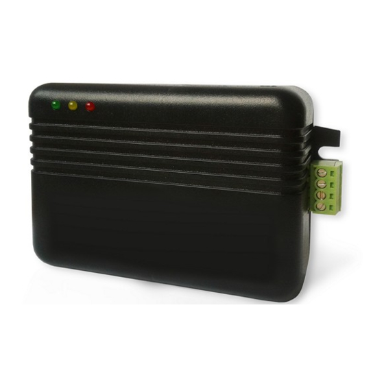
- Page 5 Operating status – LED indicators The EKO-LAN modem features three LED indicators: green, yellow and red, located as shown in Fig. 2. The frequency of the backlight and the LED colours will depend on the actual operating status of the modem. An overview of indication diagnostics and the corresponding solutions is shown in Table 1.
- Page 6 REGISTERING THE MODEM The next step to do after the EKO-LAN modem has been correctly installed and connected to the controllers is to create an account. Remote management of all installations within one account is possible on the Ekontrol.pl platform (go to the Login tab).
- Page 7 If you modify the port settings, restart the managed unit (the controller) by cycling its power supply and turning the unit on again. Next, wait 2 minutes after turning on the unit and check the LED indicators on the EKO-LAN modem by comparing their statuses to Section 3.3.
Need help?
Do you have a question about the EKO-LAN and is the answer not in the manual?
Questions and answers