Table of Contents
Advertisement
Quick Links
GB
Infrared Light Module LM-IR-16-4
Operating Instructions
Infrared
Light Module
LM-IR-16-4
V1.01
BEIER-Electronic
Winterbacher Str. 52/4, 73614 Schorndorf - Weiler
Telefon 07181/46232, Telefax 07181/45732
eMail: modellbau@beier-electronic.de
Internet:
http://www.beier-electronic.de/modellbau
28.04.2022
BEIER-Electronic
1
Advertisement
Table of Contents

Related Manuals for beier LM-IR-16-4 V1.01

Summary of Contents for beier LM-IR-16-4 V1.01
- Page 1 Infrared Light Module LM-IR-16-4 Operating Instructions Infrared Light Module LM-IR-16-4 V1.01 BEIER-Electronic Winterbacher Str. 52/4, 73614 Schorndorf - Weiler Telefon 07181/46232, Telefax 07181/45732 eMail: modellbau@beier-electronic.de Internet: http://www.beier-electronic.de/modellbau 28.04.2022 BEIER-Electronic...
-
Page 2: Table Of Contents
Special light functions at outputs 13 - 16 ..............12 Controlling the servo outputs ..................13 Controlling the motor output ..................14 Green LED on LM-IR-16-4 ..................14 PC software „LM-Teacher“ ..................15 Using software „LM-Teacher“ ................... 16 Diagnosis ........................18 Firmware update ....................... 20 BEIER-Electronic 28.04.2022... -
Page 3: Description
3, the light module must be activated in the sound teachers of the main modules. For this, at least version V1.30 of the SFR-1 Sound-Teacher and version V1.80 of the USM-RC-2 Sound-Teacher are required. Version V1.30 of the Drive-Teacher is required for the UFR-1230. 28.04.2022 BEIER-Electronic... -
Page 4: Safety Advisory
• Switch to control motor manually • Data cablel / IR-transmitter for a Road-Train Permissible ambient 0 – 60° C temperature: Permissible relative air Max. 85 % humidity: Dimensions: 58 x 44 x 17 mm Weight: 26 g BEIER-Electronic 28.04.2022... -
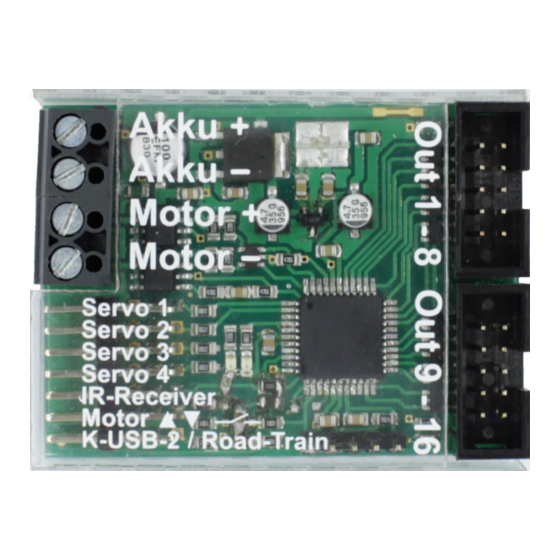
Page 5: Pin Assignment
Outputs 1 - 8 Outputs 9 - 16 X5/1 Servo 1 X5/2 Servo 2 X5/3 Servo 3 X5/4 Servo 4 X5/5 IR receiver X5/6 Switch to control motor manually X5/7 Data cable K-USB-2 / IR-transmitter diode for a Road-Train 28.04.2022 BEIER-Electronic... -
Page 6: Wiring Diagram
1230! Operation with other sound modules / speed controller is not possible. With the modules USM-RC-2, USM-RC-3 and SFR-1, you can choose between two different IR protocols (slow and fast). With the UFR-1230 there is only 1 protocol and this is activated automatically. BEIER-Electronic 28.04.2022... - Page 7 For easy and stable mounting of the IR receiver, we offer the IR-T king pin for Tamiya trucks with a special bracket in which the receiver can be clamped. For the transmission of the infrared signal, the king bolt has a continuous hole. 28.04.2022 BEIER-Electronic...
-
Page 8: Connection Of Outputs
Assignment of ribbon cable: Output Ribbon cable (X3) brown orange yellow green blue purple grey positive pole white positive pole black Ausgang Ribbon cable (X4) brown orange yellow green blue purple grey positive pole white positive pole black BEIER-Electronic 28.04.2022... -
Page 9: Connection Of Servos
Connection of motor A motor for e.g. trailer supports, ramps or tipping functions can be connected to terminal X2. It is important that the current consumption of the motor does not exceed 2 A (short time 3 A). 28.04.2022 BEIER-Electronic... -
Page 10: Connection Of Switch For Manual Motor Control
If no ID is selected on the towing vehicle, the commands for the servos and the motor output are always carried out by all light modules. This is always the initial state after switching on. BEIER-Electronic 28.04.2022... -
Page 11: Switching Outputs
The outputs 1 - 16 of the LM-IR-16-4 are 1: 1 copies of the outputs 1 - 16 of the USM-RC-3. Control via speed controller UFR-1230: Outputs 1 - 8 of the LM-IR-16-4 are 1: 1 copies of outputs 1 - 8 of the UFR-1230. The outputs 9 - 16 can be switched separately here. 28.04.2022 BEIER-Electronic... -
Page 12: Special Light Functions At Outputs 13 - 16
Short lightning pulse Output 14: Short lightning double pulse Output 15: Short double lightning pulse, slightly offset in time to output 14. Output 16: Indicator The speed of the flashers / blinkers can be set with the LM-Teacher BEIER-Electronic 28.04.2022... -
Page 13: Controlling The Servo Outputs
• LM: Servo 4 Position 2 Direct, proportional servo control via a prop. channel is also possible. More information of the servo functions can be found in the operating manuals for the SFR-1, USM-RC-2, USM-RC-3 or UFR-1230 modules. 28.04.2022 BEIER-Electronic... -
Page 14: Controlling The Motor Output
The green LED on the LM-IR-16-4 indicates different states of the module: State Steady light No IR connection Flashing regularly IR reception is ok 3 x flashing, then 3 s pause Overcurrent at switching outputs 4 x flashing, then 3 s pause Motor output overcurrent BEIER-Electronic 28.04.2022... -
Page 15: Pc Software „Lm-Teacher
Software installation After downloading the software, it must be installed on the PC. To do this, start the downloaded file and simply follow the instructions of the installation program. To start the program easily create a desktop icon. 28.04.2022 BEIER-Electronic... -
Page 16: Using Software „Lm-Teacher
French Switches to French language Dutch Switches to Dutch language Operating manual Opens this manual (PDF) Help Info Shows informations about the software Functions There are three areas in the LM-Teacher: • Configuration • Diagnosis • Firmware update BEIER-Electronic 28.04.2022... - Page 17 3 V at the motor, a speed of approx. 40% is required with a 7.2 V battery. Servo outputs In case there is no IR connection you can choose in this box whether the servo outputs should move to neutral position (center) or hold their last position. 28.04.2022 BEIER-Electronic...
-
Page 18: Diagnosis
A diagnostic function is integrated in the LM-Teacher. This feature is very helpful to check the various functions of the light module. The data cable K-USB-2 must be connected to X5/7 at the light module. The diagnosis window is divided into different areas: servo outputs, motor, miscellaneous, outputs, inputs and data. BEIER-Electronic 28.04.2022... - Page 19 The values displayed here are mainly intended for internal testing purposes. Diagnostic recording A diagnosis can be recorded in a file on the hard disk. The light module must always be connected with the data cable during recording. 28.04.2022 BEIER-Electronic...
-
Page 20: Firmware Update
Larger dealers also offer take-back points that can be used even if the product was not purchased there. We are happy to take over the professional and free disposal. To do this, send the module back to us with sufficient postage (!!!). BEIER-Electronic 28.04.2022...
Need help?
Do you have a question about the LM-IR-16-4 V1.01 and is the answer not in the manual?
Questions and answers