
Related Manuals for Oshkosh JLG ES1932i

Summary of Contents for Oshkosh JLG ES1932i
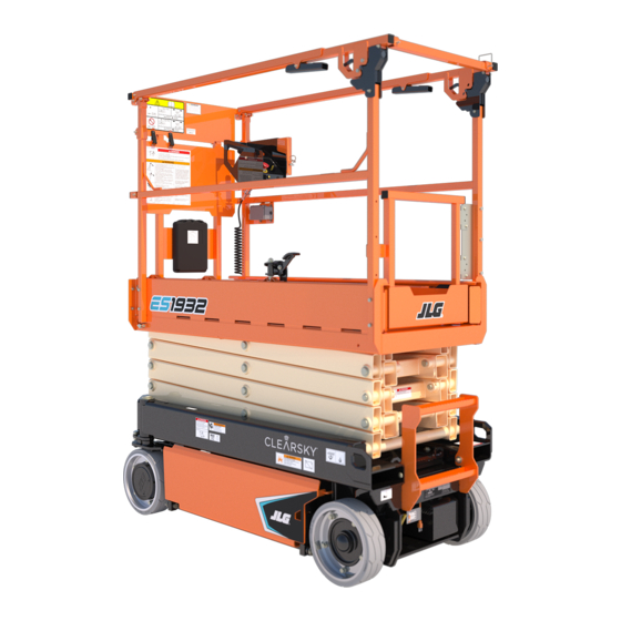
- Page 1 Operation and Safety Manual Original Instructions - Keep this manual with the machine at all times. Models ES1932i ES1932 PVC 1910, 2004 ANSI AS/NZS 31215918 April 22, 2020 - Rev B ®...
- Page 2 TO PURCHASE THIS PRODUCT PLEASE CONTACT US Equipment Financing and Extended Warranties Available Discount-Equipment.com is your online resource for commercial and industrial quality parts and equipment sales. 561-964-4949 visit us on line @ www.discount-equipment.com Select an option below to find your Equipment We sell worldwide for the brands: Genie, Terex, JLG, MultiQuip, Mikasa, Essick, Whiteman, Mayco, Toro Stone, Diamond Products, Generac Magnum, Airman, Haulotte, Barreto, Power Blanket, Nifty Lift, Atlas Copco, Chicago Pneumatic, Allmand, Miller Curber, Skyjack, Lull,...
- Page 3 WARNING Operating, servicing and maintaining this vehicle or equipment can expose you to chemicals including engine exhaust, carbon monoxide, phthalates, and lead, which are known to the State of California to cause cancer and birth defects or other reproductive harm. To minimize exposure, avoid breathing exhaust, do not idle the engine except as necessary, service your vehicle or equipment in a well-ventilated area and wear gloves or wash your hands frequently when servicing.
- Page 4 FOREWORD FOREWORD The Mobile Elevating Work Platform (MEWP) models covered in this manual are designed and tested to meet or exceed various compliance standards. Please refer to the manufacturer’s nameplate affixed to the subject MEWP for specific standard compliance information. This manual is a very important tool! Keep it with the machine at all times.
- Page 5 SAFETY ALERT SYMBOLS AND SAFETY SIGNAL WORDS SAFETY ALERT SYMBOLS AND SAFETY SIGNAL WORDS This is the Safety Alert Symbol. It is used to alert you to the potential personal injury hazards. Obey all safety messages that follow this symbol to avoid possi- ble injury or death.
- Page 6 REVISION LOG REVISION LOG Original Issue A - February 24, 2020 Revised B - April 22, 2020 31215918...
-
Page 7: Table Of Contents
TABLE OF CONTENTS SECTION - 1 - SAFETY PRECAUTIONS WALK-AROUND INSPECTION ......2-6 FUNCTION CHECK . - Page 8 TABLE OF CONTENTS SECTION - 4 - EMERGENCY PROCEDURES Steering And Traveling....... .3-11 Steering .
- Page 9 TABLE OF CONTENTS Operation ..........5-9 Tires .
- Page 10 TABLE OF CONTENTS LIST OF TABLES Minimum Approach Distances (M.A.D.)....1-6 Beaufort Scale (For Reference Only) ....1-7 High Drive Cutout Height.
-
Page 11: Section 1. Safety Precautions
SECTION 1 - SAFETY PRECAUTIONS SECTION 1. SAFETY PRECAUTIONS GENERAL PRE-OPERATION Operator Training and Knowledge This section outlines the necessary precautions for proper and safe machine usage and maintenance. In order to promote • Read, understand, and study the Operation and Safety Manual in proper machine usage, it is mandatory that a daily routine is its entirety before operating the machine. ... -
Page 12: Workplace Inspection
SECTION 1 - SAFETY PRECAUTIONS Machine Inspection • Ensure that the machine is to be used in a manner which is within the scope of its intended application as determined by JLG. • Do not operate this machine until the inspections and functional •... -
Page 13: Operation
SECTION 1 - SAFETY PRECAUTIONS OPERATION • Do not carry materials directly on platform railing unless approved by JLG. General • When two or more persons are in the platform, the operator shall be responsible for all machine operations. • Machine operation requires your full attention. Bring the machine •... -
Page 14: Trip And Fall Hazards
SECTION 1 - SAFETY PRECAUTIONS Trip and Fall Hazards • Prior to operation, ensure all gates and rails are fastened and secured in their proper position. • JLG Industries, Inc. recommends that all persons in the platform wear a full body harness with a lanyard attached to an authorized lanyard anchorage point while operating this machine. -
Page 15: Electrocution Hazards
SECTION 1 - SAFETY PRECAUTIONS Electrocution Hazards • This machine is not insulated and does not provide protection • The minimum approach distance may be reduced if insulating from contact or proximity to electrical current. barriers are installed to prevent contact, and the barriers are rated •... -
Page 16: Tipping Hazards
SECTION 1 - SAFETY PRECAUTIONS Table 1-1. Minimum Approach Distances (M.A.D.) • Before driving on floors, bridges, trucks, and other surfaces, check allowable capacity of the surfaces. VOLTAGE RANGE MINIMUM APPROACH DISTANCE • Never exceed the maximum platform capacity as specified on the (Phase to Phase) in Feet (Meters) platform. -
Page 17: Beaufort Scale (For Reference Only)
SECTION 1 - SAFETY PRECAUTIONS DO NOT OPERATE THE MACHINE WHEN WIND CONDITIONS EXCEED SPECIFICATIONS SHOWN IN SECTION 6.2 OR AS SHOWN ON THE CAPACITY PLACARD ON THE PLAT- FORM BILLBOARD. Table 1-2. Beaufort Scale (For Reference Only) WIND SPEED BEAUFORT DESCRIPTION LAND CONDITIONS... - Page 18 SECTION 1 - SAFETY PRECAUTIONS • Never attempt to use the machine as a crane. Do not tie-off machine to any adjacent structure. Never attach wire, cable, or any similar items to platform. • If the scissor arm assembly or platform is caught so that one or more wheels are off the ground, all persons must be removed before attempting to free the machine.
-
Page 19: Crushing And Collision Hazards
SECTION 1 - SAFETY PRECAUTIONS Crushing and Collision Hazards • Keep non-operating personnel at least 6 ft (1.8 m) away from machine during all operations. • Approved head gear must be worn by all operating and ground • Under all travel conditions, the operator must limit travel speed personnel. -
Page 20: Towing, Lifting, And Hauling
SECTION 1 - SAFETY PRECAUTIONS TOWING, LIFTING, AND HAULING MAINTENANCE • Never allow personnel in platform while towing, lifting, or hauling. This sub-section contains general safety precautions which must be observed during maintenance of this machine. Additional pre- • This machine should not be towed, except in the event of emer- cautions to be observed during machine maintenance are gency, malfunction, power failure, or loading/unloading. -
Page 21: Battery Hazards
SECTION 1 - SAFETY PRECAUTIONS Battery Hazards • Always relieve hydraulic pressure from all hydraulic circuits before loosening or • Always disconnect batteries when servicing electrical compo- removing hydraulic components. nents or when performing welding on the machine. • DO NOT use your hand to check for •... -
Page 22: Section 2 - User Responsibilities, Machine Preparation And Inspection
SECTION 2 - USER RESPONSIBILITIES, MACHINE PREPARATION AND INSPECTION SECTION 2. USER RESPONSIBILITIES, MACHINE PREPARATION AND INSPECTION PERSONNEL TRAINING Means to avoid the hazards of unprotected electrical con- ductors. The Mobile Elevating Work Platform (MEWP) is a personnel handling Selection of the appropriate MEWPs and available options device, so it is necessary that it be operated and maintained only by for the work to be performed considering specific job trained personnel. -
Page 23: Machine Familiarization
SECTION 2 - USER RESPONSIBILITIES, MACHINE PREPARATION AND INSPECTION PREPARATION, INSPECTION, AND MAINTENANCE Machine Familiarization NOTE: Responsibilities for familiarization may vary by region. The Inspection and Maintenance Table explains the machine inspec- tions and maintenance recommended by JLG Industries, Inc. Consult Only properly trained personnel who have received unit-specific local regulations for further requirements for MEWPs. -
Page 24: Inspection And Maintenance Table
SECTION 2 - USER RESPONSIBILITIES, MACHINE PREPARATION AND INSPECTION Inspection and Maintenance Table PRIMARY SERVICE TYPE FREQUENCY REFERENCE RESPONSIBILITY QUALIFICATION Before using each day; or Pre-Start Inspection User or Operator User or Operator Operation and Safety Manual whenever there’s an Operator change. Pre-Delivery Inspection Service and Maintenance Manual and applica- Before each sale, lease, or rental delivery. -
Page 25: Pre-Start Inspection
SECTION 2 - USER RESPONSIBILITIES, MACHINE PREPARATION AND INSPECTION PRE-START INSPECTION Walk-Around Inspection – Perform as instructed in Section 2.4. Battery – Charge as required. The Pre-Start Inspection should include each of the following: Hydraulic Oil Level – Check the hydraulic oil level in the Cleanliness –... - Page 26 SECTION 2 - USER RESPONSIBILITIES, MACHINE PREPARATION AND INSPECTION Self-Closing Swing Gate OAD01291 Lanyard Attach Point 31215918...
-
Page 27: Walk-Around Inspection
SECTION 2 - USER RESPONSIBILITIES, MACHINE PREPARATION AND INSPECTION WALK-AROUND INSPECTION Hydraulic Pump/Motor, Control Valve Installation – No unsupported wires or hoses; no damaged or broken wires. Refer to Inspection Note. Begin the Walk-Around Inspection at item 1. Continue checking each Front Wheels, Tires, Drive Motor, Steer Linkage, and item in sequence for the conditions listed in the following checklist. - Page 28 SECTION 2 - USER RESPONSIBILITIES, MACHINE PREPARATION AND INSPECTION OAD02100 31215918...
-
Page 29: Function Check
SECTION 2 - USER RESPONSIBILITIES, MACHINE PREPARATION AND INSPECTION FUNCTION CHECK Perform the Function Check as follows: From the Ground Control Panel with no load in the plat- form: a. Ensure that the key selector switch and the platform lift switch operates properly. -
Page 30: High Drive Cutout Height
SECTION 2 - USER RESPONSIBILITIES, MACHINE PREPARATION AND INSPECTION g. With the platform elevated on a smooth, firm, level sur- Table 2-2. Tilt Activation Setting face with no overhead obstructions, drive the machine to check if the high drive cutout speed limit is engaged TILT SETTING TILT SETTING Maximum Platform... -
Page 31: Section 3 - Machine Controls, Indicators, And Operation
SECTION 3 - MACHINE CONTROLS, INDICATORS, AND OPERATION SECTION 3. MACHINE CONTROLS, INDICATORS, AND OPERATION GENERAL DESCRIPTION This machine is a Mobile Elevating Work Platform (MEWP) used to posi- NOTICE tion personnel along with their necessary tools and materials at work locations. -
Page 32: Operating Characteristics And Limitations
SECTION 3 - MACHINE CONTROLS, INDICATORS, AND OPERATION OPERATING CHARACTERISTICS AND LIMITATIONS PLATFORM LOADING Placards The platform maximum rated load capacity is shown on a placard located on the platform billboard and ground control station and is Important points to remember during operation are provided at the based upon the machine positioned on a smooth, firm surface within control stations by DANGER, WARNING, CAUTION, NOTICE, and the limits of the maximum operating slope. -
Page 33: Machine Control Locations
SECTION 3 - MACHINE CONTROLS, INDICATORS, AND OPERATION MACHINE CONTROL LOCATIONS 1. Ground Control Station 2. Platform Control Station 3. Platform Manual Descent Control (T-Handle) 4. AC Plug - At Front of Machine - For Platform AC Receptacle Outlet Box 5. -
Page 34: Battery Charging
SECTION 3 - MACHINE CONTROLS, INDICATORS, AND OPERATION BATTERY CHARGING After connecting the charger to an AC outlet at the start of the charging cycle, verify normal operation of the LED indi- cators on the charger (refer to Section 6.5). The battery charger AC input plug is located inside the frame at the left rear of the machine next to the battery charger. -
Page 35: Ground Control Station
SECTION 3 - MACHINE CONTROLS, INDICATORS, AND OPERATION GROUND CONTROL STATION OAD02130 1. Ground/Platform/OFF Key Selector Switch 5. Hourmeter 2. Platform Lift/Lower Switch 6. Overload Indicator (LSS) 3. Inverter ON/OFF Switch (If Equipped) 7. MDI Indicator (If Equipped) 4. Ground Emergency Stop Button 31215918... -
Page 36: Ground/Platform/Off Key Selector Switch
SECTION 3 - MACHINE CONTROLS, INDICATORS, AND OPERATION Platform Lift/Lower Switch A three-position momentary contact switch con- DO NOT OPERATE FROM GROUND CONTROL STATION WITH PERSONNEL IN THE PLAT- trols raising and lowering of the platform from FORM EXCEPT IN AN EMERGENCY. the Ground Control Station. -
Page 37: Ground Emergency Stop Switch
SECTION 3 - MACHINE CONTROLS, INDICATORS, AND OPERATION Ground Emergency Stop Switch Overload Indicator (LSS) A red two-position emergency stop switch when posi- The Overload Indicator indicates when the platform tioned to ON with the key selector switch positioned has been overloaded. An audible alarm will also signal to ground furnishes operating power to the ground when the platform is overloaded. -
Page 38: Mdi Indicator (If Equipped)
SECTION 3 - MACHINE CONTROLS, INDICATORS, AND OPERATION MDI Indicator (If Equipped) The Multifunction Digital Indicator (MDI) displays a Battery Discharge Indicator (BDI), a LCD display showing the current hourmeter read- ing, a system distress LED, and Diagnostic Trouble Codes (DTC) when a functional problem occurs with the machine. -
Page 39: Platform Control Station
SECTION 3 - MACHINE CONTROLS, INDICATORS, AND OPERATION PLATFORM CONTROL STATION 1. Emergency Stop Switch 2. Lift/Drive Select Switch 3. Forward/Reverse/Lift/Lower Directional Arrow 4. Steer Control Switch and Direction Decal 5. Joystick Controller 6. Trigger (Enable) Switch 7. Overload Indicator (LSS) 8. -
Page 40: Platform Emergency Stop Switch
SECTION 3 - MACHINE CONTROLS, INDICATORS, AND OPERATION Platform Emergency Stop Switch Lift/Drive Select NOTE: NOTE: Both the ground and platform emergency stop buttons must be When selecting between the Lift and Drive functions the joystick set to ON in order to operate the machine. control must be returned to the neutral position for approxi- mately 1/2 second before the function change is operable. -
Page 41: Drive/Lift/Steer Joystick Control
SECTION 3 - MACHINE CONTROLS, INDICATORS, AND OPERATION Drive/Lift/Steer Joystick Control Steering And Traveling Trigger (Enable) Switch - This switch is located on the front of the joy- stick controller. The trigger switch acts as an enable and must be depressed before operating the drive, steer and lift functions. -
Page 42: Steering
SECTION 3 - MACHINE CONTROLS, INDICATORS, AND OPERATION Steering Raising And Lowering Platform On the platform control station, position the lift/ If the machine was shut down, place the key selector switch drive select switch to the drive position. to the platform position. Position emergency stop switches, one at the platform and To steer the machine, engage trigger switch and one at the ground control station to the ON position. -
Page 43: Arm Guards (If Equipped)
SECTION 3 - MACHINE CONTROLS, INDICATORS, AND OPERATION Arm Guards (If Equipped) If the machine is equipped with electronic arm guards, the platform IF THE TILT INDICATOR WARNING LIGHT/ALARM IS ACTIVATED WHEN PLATFORM IS will stop lowering at a predetermined height and the machine’s bea- RAISED LOWER PLATFORM AND DRIVE TO A SMOOTH, FIRM SURFACE WITHIN THE cons will flash at a different rate to warn ground personnel. -
Page 44: System Fault Indicator
SECTION 3 - MACHINE CONTROLS, INDICATORS, AND OPERATION System Fault Indicator Indoor/Outdoor Operation Indicator The Indoor (green) indicator and the Outdoor When this indicator light is flashing, a system fault (yellow) indicator displays which mode the has occurred, possibly stopping machine opera- machine is currently set to operate in. -
Page 45: Platform Manual Descent Control
SECTION 3 - MACHINE CONTROLS, INDICATORS, AND OPERATION PLATFORM MANUAL DESCENT CONTROL Use the Platform Manual Descent in the event of total power failure to lower the platform using gravity. The red T-handle is located on the left rear of the machine, just below the platform ladder. Look for the instruction decal located beside the T-handle. -
Page 46: 3.10 Grade And Sideslope Definition
SECTION 3 - MACHINE CONTROLS, INDICATORS, AND OPERATION 3.10 GRADE AND SIDESLOPE DEFINITION 3-16 31215918... -
Page 47: 3.11 Platform Extension
SECTION 3 - MACHINE CONTROLS, INDICATORS, AND OPERATION 3.11 PLATFORM EXTENSION To retract the deck: Press foot down on locking mechanism lever (1) until it This machine is equipped with an extension deck, giving the operator clears one of the forward platform extension locks (4 or 5). better access to certain work areas. -
Page 48: 3.12 Parking And Stowing Machine
SECTION 3 - MACHINE CONTROLS, INDICATORS, AND OPERATION 3.12 PARKING AND STOWING MACHINE Drive the machine to a well-protected and well-ventilated area. Ensure the platform is fully lowered. NOTICE WHEN THE MACHINE IS SHUT DOWN FOR OVERNIGHT PARKING OR BATTERY CHARGING, THE EMERGENCY STOP AND POWER SELECT SWITCHES MUST BE POSI- TIONED TO OFF TO PREVENT DRAINING THE BATTERIES. -
Page 49: Platform Rails Fold-Down Procedure
SECTION 3 - MACHINE CONTROLS, INDICATORS, AND OPERATION 3.13 PLATFORM RAILS FOLD-DOWN PROCEDURE (IF Fully open the swing gate and hold while folding down the RIGHT side rail. EQUIPPED) Fold down LEFT side rail. Fold down FRONT platform extension rail. To raise the rails back to the upright position, unfold the rails in the reverse sequence they were folded. - Page 50 SECTION 3 - MACHINE CONTROLS, INDICATORS, AND OPERATION 3-20 31215918...
-
Page 51: Platform With Dual Rail Extension Deck
SECTION 3 - MACHINE CONTROLS, INDICATORS, AND OPERATION Platform with Dual Rail Extension Deck ONLY FOLD DOWN THE RAILS WHEN THE MACHINE IS IN THE STOWED (PLATFORM FULLY LOWERED) POSITION. DO NOT RAISE THE PLATFORM WITH THE RAILS FOLDED DOWN. THE RAILS MUST BE IN THE UPRIGHT POSITION AND PROPERLY PINNED WHEN RAISING THE PLATFORM. - Page 52 SECTION 3 - MACHINE CONTROLS, INDICATORS, AND OPERATION Platform with Quick-Fold Rail System Release the two draw latches (1) at the front of the rail sys- tem. Squeeze both triggers (2) at the rear right and left sides of the rail system. NOTE: When the levers are squeezed, the latch is released.
-
Page 53: 3.14 Machine Lifting And Tie Down
SECTION 3 - MACHINE CONTROLS, INDICATORS, AND OPERATION 3.14 MACHINE LIFTING AND TIE DOWN Lifting The machine may be lifted using a fork lift truck. Lift only from the rear of the machine and only with the platform in the stowed position. Adjust the width of the forklift truck, lifting tines (1) to properly fit the machine forklift pockets. -
Page 54: Tie Down
SECTION 3 - MACHINE CONTROLS, INDICATORS, AND OPERATION Tie Down When transporting the machine, the platform must be fully lowered in the stowed position with the machine securely tied down to the truck or trailer deck. There are two tie-down and one lift lugs located at the front and two tie-down/lift lugs on the rear of the machine. - Page 55 SECTION 3 - MACHINE CONTROLS, INDICATORS, AND OPERATION OAD01640 31215918 3-25...
-
Page 56: 3.15 Towing
SECTION 3 - MACHINE CONTROLS, INDICATORS, AND OPERATION 3.15 TOWING It is not recommended that this machine be towed except in the event of an emergency, such as a machine malfunction or a total machine power failure. If the machine must be towed, the machine is equipped with a push button to electrically release the brakes. - Page 57 TO PURCHASE THIS PRODUCT PLEASE CONTACT US Equipment Financing and Extended Warranties Available Discount-Equipment.com is your online resource for commercial and industrial quality parts and equipment sales. 561-964-4949 visit us on line @ www.discount-equipment.com Select an option below to find your Equipment We sell worldwide for the brands: Genie, Terex, JLG, MultiQuip, Mikasa, Essick, Whiteman, Mayco, Toro Stone, Diamond Products, Generac Magnum, Airman, Haulotte, Barreto, Power Blanket, Nifty Lift, Atlas Copco, Chicago Pneumatic, Allmand, Miller Curber, Skyjack, Lull,...
-
Page 58: Section 4 - Emergency Procedures
SECTION 4 - EMERGENCY PROCEDURES SECTION 4. EMERGENCY PROCEDURES GENERAL INFORMATION Righting of Tipped Machine A fork truck of suitable capacity or equivalent equipment should be This section explains the steps to be taken in case of an emergency sit- placed under the elevated side of the chassis, with a crane or other suit- uation during operation. -
Page 59: Platform Manual Descent
SECTION 4 - EMERGENCY PROCEDURES PLATFORM MANUAL DESCENT Use the Platform Manual Descent in the event of total power failure to lower the platform using gravity. The control T-handle is located on the left rear of the machine, just below the platform ladder. Look for the instruction decal located beside the release handle. -
Page 60: Incident Notification
SECTION 4 - EMERGENCY PROCEDURES INCIDENT NOTIFICATION NOTICE JLG Industries, Inc. must be notified immediately of any incident involv- FOLLOWING ANY INCIDENT, THOROUGHLY INSPECT THE MACHINE. DO NOT ELEVATE ing a JLG product. Even if no injury or property damage is evident, JLG PLATFORM UNTIL YOU ARE SURE THAT ALL DAMAGE HAS BEEN REPAIRED, AND THAT must be contacted by telephone and provided with all necessary ALL CONTROLS ARE OPERATING CORRECTLY. -
Page 61: Section 5 - Accessories
SECTION 5 - ACCESSORIES SECTION 5. ACCESSORIES AVAILABLE ACCESSORIES Market ACCESSORY ANSI ANSI Japan China Korea (USA Only) DC/AC Power Inverter Magnetic Gate Latch ... -
Page 62: Options/Accessories Relationship Table
SECTION 5 - ACCESSORIES OPTIONS/ACCESSORIES RELATIONSHIP TABLE COMPATIBLE WITH INTERCHANGEABLE ACCESSORY INCOMPATIBLE WITH (Note 1) WITH (Note 2) Pipe Racks, Anti-Vandalism Package, Fire Extinguisher, Platform Extension Handles, DC/AC Power Inverter — — Footswitch, Dual Rails, Magnetic Gate Latch, Panel Carrier Inverter, Pipe Racks, Anti-Vandalism Package, Fire Extinguisher, Platform Extension Magnetic Gate Latch —... -
Page 63: Dc/Ac Power Inverter
SECTION 5 - ACCESSORIES DC/AC POWER INVERTER Specifications DESCRIPTION SPECIFICATION The DC to AC Power Inverter converts DC voltage from the onboard system batteries to AC voltage for use at the platform AC Electrical System Voltage (DC) output receptacle. Power Inverter: Power Bright The inverter module is mounted on the inside of the battery DC Input:... -
Page 64: Operation
SECTION 5 - ACCESSORIES MAGNETIC GATE LATCH • This inverter will only operate from a 24V power source. Do not attempt to connect the inverter to any other power source, including any AC power source. The Magnetic Gate Latch ensures the platform gate latches •... -
Page 65: Anti-Vandalism Package
SECTION 5 - ACCESSORIES ANTI-VANDALISM PACKAGE The Anti-Vandalism Package consists of two lockable covers for the Platform and Ground Control Stations that prevent unauthorized use of the machine. Locks are not provided with this kit. OAD01740 Platform Control Station Ground Control Station 1. -
Page 66: Platform Extension Handles
SECTION 5 - ACCESSORIES PLATFORM EXTENSION HANDLES The Platform Extension Handles are mounted to the top rails of the extension platform at the roller tabs. When rotated up 90°, the handles provide the operator an optional grip to push the extension platform out from its stowed position. -
Page 67: Pipe Racks
SECTION 5 - ACCESSORIES PIPE RACKS Pipe Racks store pipe or conduit inside the platform in order to prevent rail damage and optimize platform utility. The accessory consists of two racks attached to the lower platform handrail with adjustable straps that secure the load in place. NOTE: This accessory is available for ES1932 only. -
Page 68: Safety Precautions
SECTION 5 - ACCESSORIES Safety Precautions Preparation and Inspection • Ensure both racks are mounted and securely fastened to inside of platform rails. • Check for missing or damaged components. Replace if THIS ACCESSORY AFFECTS OVERALL PLATFORM CAPACITY. REFER TO CAPACITY necessary. -
Page 69: Footswitch
SECTION 5 - ACCESSORIES FOOTSWITCH The Footswitch serves as another enable switch in the function control circuit. It must be depressed in sequence with the platform control joystick trigger switch to enable operation of machine functions when using the platform controls. Power is removed from the platform controls when the footswitch is released. -
Page 70: Panel Carrier
SECTION 5 - ACCESSORIES PANEL CARRIER The Panel Carrier can transport flat sheets or panels to an elevated site by positioning them in a channel on the outside of the platform. It consists of a carrier tray that runs parallel to the length of the platform and an adjustable bracket mounted to the handrail to hold material in place. -
Page 71: Safety Precautions
SECTION 5 - ACCESSORIES Safety Precautions Preparation and Inspection • Ensure all components are secured to the platform. • Check for any missing or damaged components. Replace if necessary. MULTIPLE MATERIAL-HANDLING ACCESSORIES CAN BE INSTALLED BUT ONLY ONE • Check for loose nuts and bolts. If necessary, torque MAY BE LOADED AT A TIME UNLESS APPROVED BY JLG INDUSTRIES, INC. -
Page 72: 5.10 Jlg™ Mobile Control
SECTION 5 - ACCESSORIES 5.10 JLG™ MOBILE CONTROL Download Visit the Apple Store®, Google Play®, or The JLG Mobile Control application allows machine operators to https://www.JLG.com/mobilecontrol in order to download the drive remotely from a Bluetooth® equipped hand-held mobile JLG Mobile Control application. device. -
Page 73: Operation
SECTION 5 - ACCESSORIES Operation Download, read, and understand the JLG Mobile Control Supplement Manual from https://www.JLG.com/mobilecontrol prior to using the JLG Mobile Control. NEVER DRIVE THE MACHINE USING JLG MOBILE CONTROL WHILE STANDING IN THE PLATFORM, OR WITHOUT CLEAR LINE-OF-SIGHT BETWEEN THE MACHINE AND ITS TRAVEL PATH, AS SERIOUS INJURY COULD OCCUR TO OPERATOR OR BYSTANDER. -
Page 74: 5.11 Skysense
SECTION 5 - ACCESSORIES 5.11 SKYSENSE™ READ AND UNDERSTAND THESE INSTRUCTIONS IN THEIR ENTIRETY BEFORE OPERAT- General Information ING THE MACHINE. SKYSENSE IS NOT INTENDED TO REPLACE OR REDUCE THE NEED FOR THE OPERATOR SKYSENSE IS INTENDED TO ASSIST THE OPERATOR. SKYSENSE MAY NOT DETECT CER- TO BE AWARE OF THE ENVIRONMENT AROUND THE MACHINE. -
Page 75: Preparation And Inspection
SECTION 5 - ACCESSORIES Preparation and Inspection Remove hand or object from the sensor zone, then release the joystick and enable switch. Lower the platform to Pre-Operation Inspection: stowed. Inspect each of the SkySense tubes for dents, cracks, or other Lift the platform with no hand or object above the sensor. -
Page 76: Notification Assembly
SECTION 5 - ACCESSORIES Notification Assembly LED Indicator A bicolor LED indicator on the platform control box signals Sky- Sense activity. • No LED: Normal operation. • LED Flashing Yellow: Machine is in SkySense warning zone and will reduce to elevated drive height speed. Flash frequency correlates to closeness of the object. -
Page 77: Skysense Alarm
SECTION 5 - ACCESSORIES SkySense Alarm Override Button Activation of SkySense is also signalled by an audible alarm that The yellow override button allows operators to bypass normal indicates SkySense activity when reaching the warning or stop SkySense operation in order to move closer to an object within zones. -
Page 78: Skysense Coverage Areas
SECTION 5 - ACCESSORIES SkySense Coverage Areas Level One Sensor Cones shown are approximations for reference only. NOTE: 5-18 31215918... -
Page 79: Section 6 - General Specifications And Maintenance
SECTION 6 - GENERAL SPECIFICATIONS AND MAINTENANCE SECTION 6. GENERAL SPECIFICATIONS AND MAINTENANCE INTRODUCTION Serial Number Identification This section of the manual provides additional necessary information to the operator for proper operation and maintenance of this machine. The maintenance portion of this section is intended as information to assist the machine operator to perform daily maintenance tasks only, and does not replace the more thorough Preventive Maintenance and Inspection Schedule included in the Service and Maintenance Manual. -
Page 80: Machine Specifications
SECTION 6 - GENERAL SPECIFICATIONS AND MAINTENANCE MACHINE SPECIFICATIONS Operating Specifications ES1932 ES1932 DESCRIPTION ES1932i (ANSI, CSA, CE, GB, AUS) (JAPAN) PLATFORM Maximum Platform Height (Elevated) (Ground to Platform Floor) 19 ft (5.8 m) 19 ft (5.8 m) 19 ft (5.8 m) Lift Up Time No Load Rated Load... - Page 81 SECTION 6 - GENERAL SPECIFICATIONS AND MAINTENANCE ES1932 ES1932 DESCRIPTION ES1932i (ANSI, CSA, CE, GB, AUS) (JAPAN) Turning Radius Inside 0 in. (0 cm) 0 in. (0 cm) 0 in. (0 cm) (Curb to Curb) Outside 62.93 in (159.8 cm) 62.93 in (159.8 cm) 62.93 in (159.8 cm) CHASSIS...
-
Page 82: Platform Capacities
SECTION 6 - GENERAL SPECIFICATIONS AND MAINTENANCE Platform Capacities MAX. SIDE FORCE MAXIMUM MAXIMUM CAPACITY MAXIMUM MAXIMUM PERSONS (Platform Fully Extended MACHINE MODEL MARKET PLATFORM ALLOWED ON PLATFORM OPERATING ALLOWED IN PLATFORM CAPACITY EXTENSION WIND SPEED @ Max. Capacity) ES1932i 507 lb (230 kg) 265 lb (120 kg) 1 Person... -
Page 83: Machine Dimensions
SECTION 6 - GENERAL SPECIFICATIONS AND MAINTENANCE Machine Dimensions Tires DESCRIPTION ES1932i, ES1932 DESCRIPTION ES1932i, ES1932 12.72 in x 3.9 in Platform Height - Elevated Size 19 ft (5.8 m) (32.3 cm x 10.0 cm) (Ground to Platform Floor) Wheel Bolt Torque 120 ft. -
Page 84: Battery Charger
SECTION 6 - GENERAL SPECIFICATIONS AND MAINTENANCE BATTERY CHARGER DESCRIPTION ALL MACHINES Electrical System Voltage (DC) Battery Charger Delta-Q PRO - Eagle Performance Series Green Power - Pylon International Input: AC Input Voltage: 85-270V AC 108-132V AC 100-240V AC Nominal AC Input Voltage: 100VAC / 240VAC RMS 120VAC RMS —... -
Page 85: Delta-Q
SECTION 6 - GENERAL SPECIFICATIONS AND MAINTENANCE Delta-Q Green Power (China Only) 1. AC Voltage Input Cable 2. Charge Indicator LEDs 1. AC Voltage Input Plug 2. Charge Indicator LEDs • Battery Charging: Yellow LED - AGM - flashes quickly; •... -
Page 86: Eagle Performance
SECTION 6 - GENERAL SPECIFICATIONS AND MAINTENANCE Eagle Performance LUBRICATION Lubrication Specifications SPECIFICATIONS Multipurpose Grease having a minimum dripping point of 350° F. Excellent water resistance and adhesive qualities, and being of extreme pressure type. (Timken OK 40 pounds minimum.) Extreme Pressure Gear Lube (oil) meeting API service classification GL-5 or MIL-Spec EPGL MIL-L-2105. -
Page 87: Hydraulic Oil
SECTION 6 - GENERAL SPECIFICATIONS AND MAINTENANCE Hydraulic Oil Hydraulic Oil Specifications HYDRAULIC SYSTEM OPERATING SAE VISCOSITY GRADE MOBIL MOBIL EAL TEMPERATURE RANGE SPECIFICATION MOBILFLUID 424 ENVIRONSYN H 32 0° F to +23° F (-18° C to -5° C) ISO Viscosity Grade 10W-30 0°... -
Page 88: Hydraulic Oil Operating Chart
SECTION 6 - GENERAL SPECIFICATIONS AND MAINTENANCE Hydraulic Oil Operating Chart 00 2 9909 E 6-10 31215918... -
Page 89: Operator Maintenance
SECTION 6 - GENERAL SPECIFICATIONS AND MAINTENANCE OPERATOR MAINTENANCE Scissor Arm - Safety Prop NEVER WORK UNDER AN ELEVATED PLATFORM UNTIL IT HAS BEEN RESTRAINED FROM MOVEMENT WITH THE SAFETY PROP, BLOCKING OR OVERHEAD SLING. THE SAFETY PROP MUST BE USED WHENEVER MAINTENANCE PERFORMED ON THE MACHINE REQUIRES THE SCISSOR ARMS TO BE RAISED AND ONLY WITH NO LOAD IN THE PLATFORM Prop Engaged... -
Page 90: Hydraulic Oil Check Procedure
SECTION 6 - GENERAL SPECIFICATIONS AND MAINTENANCE Hydraulic Oil Check Procedure Check the hydraulic oil daily to ensure proper operation of the machine. Check the hydraulic oil level only when the machine is in the stowed position. Ensure the hydraulic oil has warmed to operating tempera- ture before checking the reservoir. -
Page 91: Battery Maintenance And Safety Practices
SECTION 6 - GENERAL SPECIFICATIONS AND MAINTENANCE Battery Maintenance and Safety Practices Check the electrolyte level of the batteries often, adding only distilled water when required. When fully charged, battery fluid level should be 1/8" below vent tubes. NOTE: These instructions are for unsealed (wet) batteries only. •... -
Page 92: Battery Quick-Disconnect
SECTION 6 - GENERAL SPECIFICATIONS AND MAINTENANCE Battery Quick-Disconnect Wheel and Tire Replacement Machines equipped with the battery quick- JLG recommends that any replacement tire be the same size and brand disconnect allow all machine power to be eas- as originally installed on the machine or offered by JLG as an approved ily disconnected at the batteries without replacement. -
Page 93: Wheel Installation
SECTION 6 - GENERAL SPECIFICATIONS AND MAINTENANCE Wheel Installation Tighten bolts in stages. Following the recommended sequence, tighten each bolt per wheel torque of 163 Nm (120 ft.lb.). It is extremely important to apply and maintain proper wheel mount- ing torque. TORQUE SEQUENCE 1st Stage 2nd Stage... -
Page 94: Supplemental Information
SECTION 6 - GENERAL SPECIFICATIONS AND MAINTENANCE SUPPLEMENTAL INFORMATION The following information is provided in accordance with the require- ments of the European Machinery Directive 2006/42/EC and is only applicable to CE machines. For electric powered machines, the equivalent continuous A-Weighted sound pressure level at the work platform is less than 70dB(A). -
Page 95: Decal Installation
SECTION 6 - GENERAL SPECIFICATIONS AND MAINTENANCE DECAL INSTALLATION OAD01720 31215918 6-17... - Page 96 SECTION 6 - GENERAL SPECIFICATIONS AND MAINTENANCE 1. ANSI 2. CE/AUS 3. Dual Side Rails 4. Folding Rails OAD01730 6-18 31215918...
- Page 97 SECTION 6 - GENERAL SPECIFICATIONS AND MAINTENANCE ENGLISH ENG/KOR ENG/CHI (GB) SPA/POR ENG/SPA ENG/FRE CE/JAPAN ENG/CHI ITEM (1001209907-E) (1001209908-C) (1001209909-E) (1001209910-C) (1001209911-C) (1001219265-C) (1001209913-D) (1001209914-D) (1001222745-B) 1701504 1701504 1701504 1701504 1701504 1701504 1701504 1701504 1701504 1701640 1701640 1701640 1701640 1701640 1701640 1701640 1701640...
- Page 98 SECTION 6 - GENERAL SPECIFICATIONS AND MAINTENANCE ENGLISH ENG/KOR ENG/CHI (GB) SPA/POR ENG/SPA ENG/FRE CE/JAPAN ENG/CHI ITEM (1001209907-E) (1001209908-C) (1001209909-E) (1001209910-C) (1001209911-C) (1001219265-C) (1001209913-D) (1001209914-D) (1001222745-B) 1001211777 1001215751 1001215752 1001216650 1001215754 1001215755 1001219172 1001219172 1001215752 1001211779 1001211779 1001211779 1001215748 1001211779 1001211779 1001219171 1001219171...
-
Page 99: Diagnostic Trouble Codes (Dtc)
SECTION 6 - GENERAL SPECIFICATIONS AND MAINTENANCE DIAGNOSTIC TROUBLE CODES (DTC) To troubleshoot multiple DTCs, start with the DTC with the higher first two digits. If a correction is made during a check, conclude the check by NOTICE cycling the machine power off then back on, using the emergency stop switch. - Page 100 SECTION 6 - GENERAL SPECIFICATIONS AND MAINTENANCE Flash Help Message Alarm Action Trigger Code • Platform Mode and no Faults are active. EVERYTHING OK None None · No Motion restrictions • Ground Mode and no Faults are active. GROUND MODE OK None None · ...
- Page 101 SECTION 6 - GENERAL SPECIFICATIONS AND MAINTENANCE Flash Help Message Alarm Action Trigger Code • A period of time elapsed without activity and the Control System entered a low-power state to preserve battery charge (2 hours). Cycle the Ground EMS in GroundMode or the Platform EMS in Plat- FUNCTIONS LOCKED OUT –...
- Page 102 SECTION 6 - GENERAL SPECIFICATIONS AND MAINTENANCE Flash Help Message Alarm Action Trigger Code • MoveState = LIFT • The Drive - Lift Selector Switch indicates that both functions are FUNCTION PROBLEM – DRIVE & LIFT ACTIVE • DriveState = PREVENTED selected simultaneously.
- Page 103 SECTION 6 - GENERAL SPECIFICATIONS AND MAINTENANCE Flash Help Message Alarm Action Trigger Code • Driving is not possible since the vehicle is charging. DRIVE PREVENTED – CHARGER CONNECTED None • DriveState = PREVENTED DRIVE & LIFT UP PREVENTED – CHARGER •...
- Page 104 SECTION 6 - GENERAL SPECIFICATIONS AND MAINTENANCE Flash Help Message Alarm Action Trigger Code • Heatsink temperature above 203°F (95° C). • Possible Cause: • DriveState = PREVENTED POWER MODULE TOO HOT - PLEASE WAIT None • Controller is operating in an extreme environment. •...
- Page 105 SECTION 6 - GENERAL SPECIFICATIONS AND MAINTENANCE Flash Help Message Alarm Action Trigger Code • The Ground Module measured excessively high battery voltage (VBAT) (>32.0V) and de-energized the Main Line Contactor and Bat- BATTERY VOLTAGE TOO HIGH – SYSTEM • Enter SafeMode None tery Relay to protect system devices and was unable to bring voltage SHUTDOWN...
- Page 106 SECTION 6 - GENERAL SPECIFICATIONS AND MAINTENANCE Flash Help Message Alarm Action Trigger Code 4477 Lift Down = PREVENTED • The Ground Module momentarily measured excessively high battery BATTERY VOLTAGE TOO HIGH – FORCING DIS- None Lift Up = PREVENTED voltage (VBAT) (>32.0V) and entered SafeMode.
- Page 107 TO PURCHASE THIS PRODUCT PLEASE CONTACT US Equipment Financing and Extended Warranties Available Discount-Equipment.com is your online resource for commercial and industrial quality parts and equipment sales. 561-964-4949 visit us on line @ www.discount-equipment.com Select an option below to find your Equipment We sell worldwide for the brands: Genie, Terex, JLG, MultiQuip, Mikasa, Essick, Whiteman, Mayco, Toro Stone, Diamond Products, Generac Magnum, Airman, Haulotte, Barreto, Power Blanket, Nifty Lift, Atlas Copco, Chicago Pneumatic, Allmand, Miller Curber, Skyjack, Lull,...
Need help?
Do you have a question about the JLG ES1932i and is the answer not in the manual?
Questions and answers