Table of Contents
Advertisement
Advertisement
Table of Contents

Subscribe to Our Youtube Channel
Related Manuals for Alpha Outback Energy SPC Series


Summary of Contents for Alpha Outback Energy SPC Series
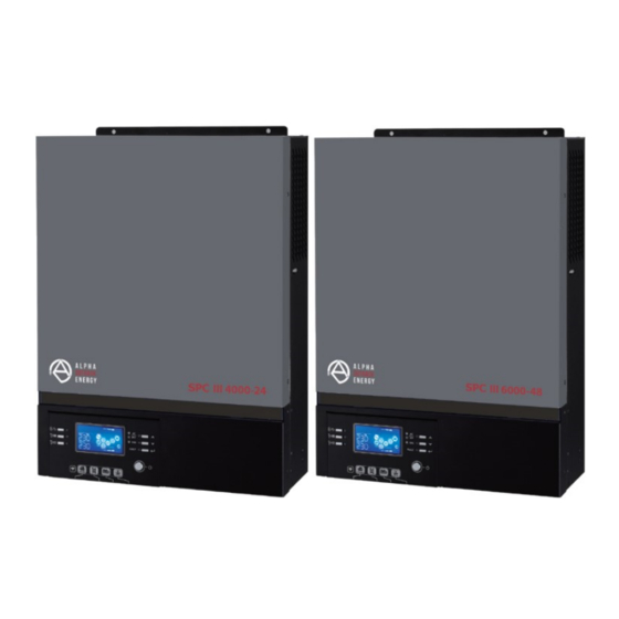
- Page 1 SPCIII4000-24 / SPCIII6000-48 Solar inverter / charger USER MANUAL...
-
Page 2: Table Of Contents
Table of Contents ABOUT THIS MANUAL ................................. 2 Purpose..................................... 2 Scope ....................................2 SAFETY INSTRUCTIONS ................................2 INTRODUCTION ..................................... 3 Features ..................................... 3 Basic System Architecture ............................... 3 Product Overview ................................4 INSTALLATION ....................................5 Unpacking and Inspection ............................... 5 Preparation .................................. -
Page 3: About This Manual
ABOUT THIS MANUAL Purpose This manual describes the assembly, installation, operation and troubleshooting of this unit. Please read this manual carefully before installations and operations. Keep this manual for future reference. Scope This manual provides safety and installation guidelines as well as information on tools and wiring. SAFETY INSTRUCTIONS WARNING: All safety instructions in this document must be read, understood and followed. -
Page 4: Introduction
INTRODUCTION This is a multi-function inverter, combining functions of inverter, solar charger and battery charger to offer uninterruptible power support in a single package. The comprehensive LCD display offers user-configurable and easy-accessible button operations such as battery charging current, AC or solar charging priority, and acceptable input voltage based on different applications. -
Page 5: Product Overview
Product Overview LCD display Status indicator Charging indicator Fault indicator Function buttons Power on/off switch AC input AC output PV input 10. Battery input 11. Circuit breaker 12. Remote LCD panel communication port 13. Dry contact 14. USB communication port 15. -
Page 6: Installation
INSTALLATION Unpacking and Inspection Before installation, please inspect the content. Be sure that nothing inside the package is damaged. You should have received the following items inside the package: Inverter x 1 User manual x 1 RS232 Communication cable x 1 Software CD x 1 DC Fuse x 1 Preparation... -
Page 7: Battery Connection
SUITABLE FOR MOUNTING ON CONCRETE OR OTHER NON-COMBUSTIBLE SURFACE ONLY. Mounting the unit by screwing the three screws as shown below. It’s recommended to use M4 or M5 screws. Battery Connection For safety operation and regulation compliance, it’s requested to install a separate DC over-current CAUTION: protector or disconnection device between battery and the inverter. - Page 8 Please follow below steps to implement battery connection: 1. SPCIII4000-24 model supports 24VDC system and SPCIII6000-48 model supports 48VDC system. Connect all battery packs as below chart. It is recommend to connect minimum of 100Ah capacity battery for SPCIII4000-24 model and 200Ah capacity battery for SPCIII6000-48 model. Inverter 4KW 2.
-
Page 9: Ac Input/Output Connection
WARNING: Shock Hazard Installation must be performed with care due to high battery voltage in series. CAUTION!! Do not place anything between inverter terminals and the ring terminals. Otherwise, overheating may occur. CAUTION!! Do not apply anti-oxidant substance on the terminals before terminals are securely tightened. -
Page 10: Pv Connection
Insert AC output wires according to polarities indicated on terminal block and tighten terminal screws. Be sure to connect the grounding wire ( ) first. → Ground (yellow-green) → LINE (brown or black) → Neutral (blue) Make sure the wires are securely connected. CAUTION: Appliances such as air conditioner required at least 2~3 minutes to spool up because it needs to have enough time to balance refrigerant gas inside of circuits. - Page 11 PV Module Selection: When selecting proper PV modules, please be sure to consider the following parameters: 1. Open circuit Voltage (Voc) of PV modules not to exceeds maximum PV array open circuit voltage of the inverter. 2. Open circuit Voltage (Voc) of PV modules should be higher than the start-up voltage. 3.
-
Page 12: Final Assembly
Final Assembly After connecting all wirings, replace the bottom cover as shown below. Remote Display Panel Installation The LCD module can be removed and installed in a remote location with an optional communication cable. Please take the following steps to implement this remote panel installation. Step 1. - Page 13 Step 2. Prepare your mounting holes in the marked locations as shown in the illustration below. The LCD module then can be securely mounted to your desired location. Ø5-Ø9 Note: Wall installation should be implemented with the proper screws to the right. Step 3.
-
Page 14: Communication Options
Communication Options Serial Connection Please use the supplied serial cable to connect the inverter with your pc. Install the monitoring software from the bundled CD and follow the on-screen instructions to complete your installation. For detailed software operation, refer to the software user manual on the bundled CD. Wi-Fi Connection This unit is equipped with a Wi-Fi transmitter. -
Page 15: Operation
OPERATION Power ON/OFF Once the unit has been properly installed and the batteries are connected well, simply press On/Off switch (located on the LCD module) to turn on the unit. Operation and Display Panel The operation and the LCD module, shown in the chart below, includes six indicators, six function keys, on/off switch and a LCD display, indicating the operating status and input/output power information. -
Page 16: Lcd Display Icons
Function Keys Function Key Description Exit the setting USB function setting Select USB OTG functions Setup the timer for prioritizing the output Timer setting for the Output source priority source Timer setting for the Charger source Setup the timer for prioritizing the priority charger source To last selection... - Page 17 Icon Function description Battery Information When battery is charging, it will present battery charging status. Status Battery voltage LCD Display <2V/cell 4 bars will flash in turns. Bottom bar will be on and the other three bars will flash in 2 ~ 2.083V/cell Constant Current turns.
-
Page 18: Lcd Setting
LCD Setting General Setting After pressing and holding “ ” button for 3 seconds, the unit will enter th p Mode. Press “ ” or “ ” button e Setu to select setting programs. Press “ ” button to confirm you selection or “ ”... - Page 19 Program Description Selectable option Appliances (default) If selected, acceptable AC input voltage range will be within 90-280VAC. AC input voltage range If selected, acceptable AC input voltage range will be within 170-280VAC. AGM (default) Flooded User-Defined If “User-Defined” is selected, battery charge voltage and low DC cut-off voltage can be set up in program 26, 27 and 29.
- Page 20 Program Description Selectable option party Lithium battery If selected, programs of 02, 26, 27 and 29 will be automatically set up. No need for further Battery type setting. Please contact battery supplier for installation procedure. Restart disable (default) Restart enable Auto restart when overload occurs Restart enable...
- Page 21 Program Description Selectable option Available options for 24V model: 23.0V (default) Setting range is from 22V to 25.5V. Increment of each click is 0.5V. Setting voltage point back to utility source when selecting “SBU” (SBU Available options for 48V model: priority) in program 01.
- Page 22 Program Description Selectable option Only Solar Solar energy will be the only charger source no matter utility is Charger source priority: available or not. configure charger source priority If this inverter/charger is working in Battery mode, only solar energy can charge battery. Solar energy will charge battery if it's available and sufficient.
- Page 23 Program Description Selectable option Bypass disable (default) Bypass enable Overload bypass: When enabled, the unit will transfer to line mode if overload occurs in battery mode. Record enable (default) Record disable Record Fault code SPCIII6000-48 default setting: SPCIII4000-24 default 56.4V setting: 28.2V Bulk charging voltage (C.V voltage)
- Page 24 Program Description Selectable option Low DC cut-off voltage: SPCIII4000-24 default s SPCIII6000-48 default setting: If battery power is setting: 21.0V 42.0V only power source available, inverter will shut down. If PV energy and battery power are available, inverter will charge battery without AC output.
- Page 25 Program Description Selectable option 30days (default) Setting range is from 0 to 90 Equalization interval days. Increment of each click is 1 Enable Disable (default) Equalization activated If equalization function is enabled in program 30, this program immediately can be set up. If “Enable” is selected in this program, it’s to activate battery equalization immediately and LCD main page will shows “...
- Page 26 Program Description Selectable option 30 minutes 60 minutes Data log recorded interval *The maximum data log number is 1440. If it’s over 1440, it will re-write the first log. For minute setting, the range is from 0 to 59. Time setting – Minute For hour setting, the range is from 0 to 23.
- Page 27 Procedure LCD Screen Press and hold “ ” button for 3 seconds to enter USB function setting mode. Step 1: Press “ ”, “ ” or “ ” button to enter the selectable setting programs Step 2: (detail descriptions in Step 3). Step 3: Please select setting program by following the procedure.
- Page 28 2. Timer Setting for Output Source Priority This timer setting is to set up the output source priority per day. Procedure LCD Screen Press and hold “ ” button for 3 seconds to enter Timer Setup Mode for output Step 1: source priority.
-
Page 29: Display Setting
Step 3: Please select setting program by following each procedure. Program# Operation Procedure LCD Screen Press “ ” button to set up Solar First Timer. Press “ ” button to select staring time. Press “ ” or “ ” button to adjust values and press “ ”... - Page 30 Selectable information LCD display PV current = 2.5A PV current PV power = 500W PV power AC and PV charging current=50A PV charging current=50A Charging current AC charging current=50A Page 29 to 62...
- Page 31 Selectable information LCD display AC and PV charging power=500W PV charging power=500W Charging power AC charging power=500W Battery voltage=25.5V, output voltage=230V Battery voltage and output voltage Output frequency=50Hz Output frequency Load percent=70% Load percentage Page 30 to 62...
- Page 32 Selectable information LCD display When connected load is lower than 1kVA, load in VA will present xxxVA like below chart. Load in VA When load is larger than 1kVA (≧1KVA), load in VA will present x.xkVA like below chart. When load is lower than 1kW, load in W will present xxxW like below chart.
- Page 33 Selectable information LCD display This PV month energy = 388kWh, Load month energy= 988kWh. PV energy generated this month and Load output energy this month. This PV year energy = 3.88MWh, Load year energy = 9.88MWh. PV energy generated this year and Load output energy this year.
-
Page 34: Operating Mode Description
Selectable information LCD display Secondary CPU version 00003.03. Secondary CPU version checking. Wi-Fi version 00000.24. Wi-Fi version checking. Operating Mode Description Operation mode Description LCD display Charging by utility and PV energy. Charging by utility. Standby mode Note: *Standby mode: No output is supplied by inverter is not turned on the unit but it still can... - Page 35 Operation mode Description LCD display Grid and PV power are available. Grid is available. Fault mode Note: *Fault mode: Errors are No charging at all no caused by inside circuit matter if grid or PV power error or external reasons is available.
- Page 36 Operation mode Description LCD display If either “SUB” (solar first) or “SBU” is selected as output source priority and battery is not connected, solar energy and the utility will provide the loads. The unit will provide output power from the mains. It Line Mode will also charge the battery at line mode.
-
Page 37: Battery Equalization Description
Battery Equalization Description Battery equalization function is built into the charge controller. It reverses the build-up of negative chemical effects such as stratification, a condition where acid concentration is greater at the bottom of the battery than at the top. Equalization also helps to remove sulfate crystals that may have built up on the plates. -
Page 38: Fault Reference Code
However, in Equalize Mode, if the battery equalization timer runs out and the battery voltage doesn’t recover to the battery equalization voltage point, the charge controller will extend the battery equalized time until battery voltage achieves equalization voltage. If the battery voltage is still lower than equalization voltage when the extension runs out, the charge controller will stop equalization and return to the floating charging stage. -
Page 39: Warning Indicator
Warning Indicator Icon Warning Code Warning Event Audible Alarm flashing Fan is locked when inverter is on. Beep three times every second Over temperature None Battery is over-charged Beep once every second Low battery Beep once every second Overload Beep once every 0.5 second Output power derating Beep twice every 3 seconds PV energy is low. -
Page 40: Specifications
SPECIFICATIONS Table 1 Line Mode Specifications INVERTER MODEL SPCIII4000-24 SPCIII6000-48 Input Voltage Waveform Sinusoidal (utility or generator) Nominal Input Voltage 230Vac 170Vac±7V (UPS); Low Loss Voltage 90Vac±7V (Appliances) 180Vac±7V (UPS); Low Loss Return Voltage 100Vac±7V (Appliances) High Loss Voltage 280Vac±7V High Loss Return Voltage 270Vac±7V Max AC Input Voltage... - Page 41 Table 2 Inverter Mode Specifications INVERTER MODEL SPCIII4000-24 SPCIII6000-48 Rated Output Power 4KVA/4KW 6KVA/6KW Output Voltage Waveform Pure Sine Wave Output Voltage Regulation 230Vac±10% Output Frequency 50Hz Peak Efficiency 5s@≥110% load; 10s@105%~110% load Overload Protection Surge Capacity 2* rated power for 5 seconds Nominal DC Input Voltage 24Vdc 48Vdc...
- Page 42 Table 3 Charge Mode Specifications Utility Charging Mode INVERTER MODEL SPCIII4000-24 SPCIII6000-48 Charging Algorithm 3-Step AC Charging Current (Max) 100Amp (@V =230Vac) Bulk Flooded Battery 29.2Vdc 58.4Vdc Charging AGM / Gel Battery 28.2Vdc 56.4Vdc Voltage Floating Charging Voltage 27Vdc 54Vdc Battery Voltage, per cell Charging Current, % 2.43Vdc (2.35Vdc)
-
Page 43: Trouble Shooting
TROUBLE SHOOTING Problem LCD/LED/Buzzer Explanation / Possible cause What to do Unit shuts down LCD/LEDs automatically buzzer will be active The battery voltage is too low 1. Re-charge battery. during startup for 3 seconds and (<1.91V/Cell) 2. Replace battery. process. then complete off. -
Page 44: Appendix A: Approximate Back-Up Time Table
Problem LCD/LED/Buzzer Explanation / Possible cause What to do Restart the unit, if the error Buzzer beeps Fault code 55 Output voltage is unbalanced. happens again, please continuously and return to repair center. red LED is on. PV input voltage is beyond the Reduce the number of PV Fault code 59 specification. -
Page 45: Appendix B: Bms Communication Installation
Appendix B: BMS Communication Installation Introduction If connecting to lithium battery, it is recommended to purchase a custom-made RJ45 communication cable. Please check with your dealer or integrator for details. This custom-made RJ45 communication cable delivers information and signal between lithium battery and the inverter. - Page 46 Step 2. Switch on Lithium battery by pressing the reset button. Step 3. Turn on the inverter. Step 4. Be sure to select battery type as “Lib” in LCD program 5. If communication between the inverter and battery is successful, the battery icon on LCD display will flash.
- Page 47 ESS LIO-I 4810 ID switch ID Switch indicates the unique ID code for each battery module. It's required to assign an identical ID to each battery module for normal operation. We can set up the ID code for each battery module by rotating the PIN number on the ID switch.
- Page 48 Step 3: Turn the breaker switch “ON". Now, the battery module is ready for DC output. Step 4: Press Power on/off button on battery module for 5 secs, the battery module will start up. *If the manual button cannot be approached, just simply turn on the inverter module. The battery module will be automatically turned on.
- Page 49 PYLONTECH Lithium Battery Communication Configuration ①Dip Switch: There are 4 Dip Switches that sets different baud rate and battery group address. If switch position is turned to the “OFF” position, it means “0”. If switch position is turned to the “ON” position, it means “1”. Dip 1 is “ON”...
- Page 50 Installation and Operation After configuration, please install LCD panel with inverter and Lithium battery with the following steps. Step 1. Use custom-made RJ45 cable to connect inverter and Lithium battery. Step 2. Switch on Lithium battery. Step 3. Press more than three seconds to start Lithium battery. Output power is ready. Step 4.
- Page 51 WECO Step 1. Use a custom-made RJ45 cable to connect inverter and Lithium battery. Step 2. Switch on Lithium battery. Step 3. Turn on the inverter. Step 4. Be sure to select battery type as “WEC” in LCD program 5. If communication between the inverter and battery is successful, the battery icon on LCD display will “flash”.
- Page 52 SOLTARO Step 1. Use a custom-made RJ45 cable to connect inverter and Lithium battery. Step 2. Open DC isolator and switch on Lithium battery. Step 3. Turn on the inverter. Step 4. Be sure to select battery type as “SOL” in LCD program 5. If communication between the inverter and battery is successful, the battery icon on LCD display will “flash”.
- Page 53 LCD Display Information “ ” or “ ” button to switch LCD display information. It will show battery pack and battery group Press number before “Main CPU version checking” as shown below. Selectable information LCD display Battery pack numbers = 3, battery group numbers = 1 Battery pack numbers &...
-
Page 54: Appendix C: The Wi-Fi Operation Guide In Remote Panel
Appendix C: The Wi-Fi Operation Guide in Remote Panel 1. Introduction Wi-Fi module can enable wireless communication between off-grid inverters and monitoring platform. Users have complete and remote monitoring and controlling experience for inverters when combining Wi-Fi module with WatchPower APP, available for both iOS and Android based device. All data loggers and parameters are saved in iCloud. - Page 55 2-2. Initial Setup Step 1: Registration at first time After the installation, please tap the shortcut icon to access this APP on your mobile screen. In the screen, tap “Register” to access “User Registration” page. Fill in all required information and scan the remote icon.
- Page 56 Enter the “SettingsWi-Fi” and select connected Wi-Fi name. The connected Wi-Fi name is the same to your Wi-Fi PN number and enter default password “12345678”. Then, return to WatchPower APP and tap “ ” button when Wi-Fi module is connected successfully. Step 3: Wi-Fi Network settings icon to select your local Wi-Fi router name (to access the internet) and enter password.
- Page 57 If the connection fails, please repeat Step 2 and 3. Diagnose Function If the module is not monitoring properly, please tap “ ” on the top right corner of the screen for further details. It will show repair suggestion. Please follow it to fix the problem. Then, repeat the steps in the chapter 4.2 to re-set network setting.
- Page 58 2-3. Login and APP Main Function After finishing the registration and local Wi-Fi configuration, enter registered name and password to login. Note: Tick “Remember Me” for your login convenience afterwards. Overview After login is successfully, you can access “Overview” page to have overview of your monitoring devices, including overall operation situation and Energy information for Current power and Today power as below diagram.
- Page 59 Devices Tap the icon (located on the bottom) to enter Device List page. You can review all devices here by adding or deleting Wi-Fi Module in this page. Add device Delete device icon on the top right corner and manually enter part number to add device. This part number label is pasted on the bottom of remote LCD panel.
- Page 60 In ME page, users can modify “My information”, including【User’s Photo】, 【Account security】, 【Modify password】, 【Clear cache】, and【Log-out】, shown as below diagrams. 2-4. Device List In Device List page, you can pull down to refresh the device information and then tap any device you want to check up for its real-time status and related information as well as to change parameter settings.
- Page 61 Device Mode On the top of screen, there is a dynamic power flow chart to show live operation. It contains five icons to present PV power, inverter, load, utility and battery. Based on your inverter model status, there will be 【Standby Mode】, 【Line Mode】, 【Battery Mode】.
- Page 62 Device Information Data Users can check up 【Basic Information】, 【Product Information】, 【Rated information】, 【History】, and 【Wi-Fi Module Information】by swiping left. Swipe left 【Basic Information】 displays basic information of the inverter, including AC voltage, AC frequency, PV input voltage, Battery voltage, Battery capacity, Charging current, Output voltage, Output frequency, Output apparent power, Output active power and Load percent.
- Page 63 Parameter Setting This page is to activate some features and set up parameters for inverters. Please note that the listing in “Parameter Setting” page in below diagram may differ from the models of monitored inverter. Here will briefly highlight some of it, 【Output Setting】, 【Battery Parameter Setting】, 【Enable/ Disable items】,【Restore to the defaults】to illustrate.
- Page 64 Item Description Charger source To configure charger source priority. priority: Max. charging current It’s to set up battery charging parameters. The selectable values in Max. AC charging different inverter model may vary. current: Please see product manual for the details. Float charging voltage It’s to set up battery charging parameters.
Need help?
Do you have a question about the SPC Series and is the answer not in the manual?
Questions and answers