
Subscribe to Our Youtube Channel
Related Manuals for Load Cell Systems WDESK-R

Summary of Contents for Load Cell Systems WDESK-R
- Page 1 ENGLISH ENGLISH ENGLISH ENGLISH Installation and User Manual version 1.10 WDESK-R/L WINOX-R/L/2L 3/6/14 Products...
- Page 2 SYMBOLS Here are the symbols used in the manual to draw the reader's attention: Caution! Risk of electric shock. Caution! This operation must be performed by skilled personnel. Pay particular attention to the following instructions. Further information. WARRANTY 24 months from the date of the delivery note. Warranty covers only failures of defective components (due to construction defects or defects in materials) and includes replacement or repair of the components and related labor costs.
-
Page 3: Table Of Contents
TABLE OF CONTENTS USER WARNINGS ........................1 RECOMMENDATIONS FOR CORRECT INSTALLATION OF WEIGHING INSTRUMENTS . 1 RECOMMENDATIONS FOR CORRECT INSTALLATION OF THE LOAD CELLS ....2 LOAD CELL INPUT TEST (QUICK ACCESS) ................4 LOAD CELL TESTING ......................4 MAIN SPECIFICATIONS OF THE INSTRUMENT ..............5 BUFFER BATTERY ........................ - Page 4 ANALOG OUTPUT(ONLY FOR INSTRUMENTS WHERE THIS OPTION IS AVAILABLE) .. 31 SERIAL COMMUNICATION SETTING ................... 33 RS232 SERIAL COMMUNICATION....................34 RS485 SERIAL COMMUNICATION....................34 DIRECT CONNECTION BETWEEN RS485 AND RS232 WITHOUT CONVERTER ....... 34 WEIGHT READING VIA SERIAL PORT ................. 35 WEIMOD MODE ..........................
- Page 5 RESUME BATCHING AFTER A POWER CUT ............... 50 CONSUMPTION ........................50 CONSUMPTION DELETION ....................50 ALARMS..........................51 PRINTING EXAMPLES ......................54 RESERVED FOR THE INSTALLER ..................56 MENU LOCKING ........................56 MENU UNLOCKING ........................ 56 TEMPORARY MENU UNLOCKING ..................56 SETTING UNLOCK PASSWORD ...................
-
Page 6: User Warnings
USER WARNINGS RECOMMENDATIONS FOR THE PROPER USE OF WEIGHING INSTRUMENT Keep away from heat sources and direct sunlight Repair the instrument from rain (except special IP versions) Do not wash with water jets (except special IP versions) Do not dip in water Do not spill liquid on the instrument Do not use solvents to clean the instrument Do not install in areas subject to explosion hazard (except special Atex versions) -
Page 7: Recommendations For Correct Installation Of The Load Cells
RECOMMENDATIONS FOR CORRECT INSTALLATION OF THE LOAD CELLS SIZING OF LOAD CELLS CAPACITY For safety reasons, in case of static weighing, it is advisable to use the load cells at a maximum of 70-80% of its nominal capacity (assuming that the load is uniformly distributed over the entire weighed structure);... - Page 8 EARTHING THE WEIGHED STRUCTURE By means of a copper wire with suitable cross-section, connect the cell upper support plate with the lower support plate, then connect all the lower plates to a single earthing system. Electrostatic charges accumulated because of the product rubbing against the pipes and the weighed container walls are discharged to the ground without going through or damaging the load cells.
-
Page 9: Load Cell Input Test (Quick Access)
LOAD CELL INPUT TEST (QUICK ACCESS) From the weight display, press for 3 seconds; the response signal of the load cells is displayed, expressed in mV with four decimals. LOAD CELL TESTING Load cell resistance measurement (use a digital multimeter): - Disconnect the load cells from the instrument and check that there is no moisture in the cell junction box caused by condensation or water infiltration. -
Page 10: Main Specifications Of The Instrument
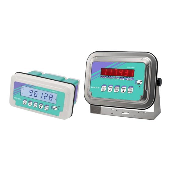
The instrument can be connected to a CLM serie intelligent junction box or to a weight transmitter. Display: LED or signalling Model Display Digit height symbols WDESK-R Red LED, 6 digits, 7 segments, 20 mm WINOX-R semi-alphanumeric WDESK-L Backlit LCD, 6 digits, 7 segments,... - Page 11 D – D-Sub connector 122x226x189 mm IP40 protection rating 96x186 mm (connectors included) Front panel IP67 protection rating Power supply included X - Atex cable gland 122x226x164 mm IP67 Atex II3GD version 96x186 mm (connectors included) (areas 2 -22) IP67 protection rating Wall installation with bracket 122x230x250 mm ca.
-
Page 12: Buffer Battery
Wall installation with bracket 206x286x187 mm ca. (can also be installed on table) (bracket included) BUFFER BATTERY The instrument is equipped with an internal battery that allows to keep active the internal clock even in the event of power failure. At the first start and after long periods of inactivity, leave the instrument on for at least 12 hours to fully charge the battery. -
Page 13: Technical Specifications
TECHNICAL SPECIFICATIONS POWER SUPPLY and CONSUMPTION (VDC) 12/24 VDC ±10%; 6 W (standard) 115/230 VAC; 50-60 Hz; 6 VA POWER SUPPLY and CONSUMPTION (VAC) (optional only for WDESK-P, WINOX-P) NO. OF LOAD CELLS IN PARALLEL and SUPPLY max 8 (350 ohm); 5 VDC / 120 mA LINEARITY / ANALOG OUTPUT LINEARITY <... -
Page 14: Electrical Connections
ELECTRICAL CONNECTIONS BASIC INFORMATION - It is recommended that the power supply negative pole be grounded (WDESK-D, WINOX: connect the earthing system to the dedicated external terminal ). - It is possible to supply up to eight 350 ohm load cells or sixteen 700 ohm load cells. - For 4-wire load cells, make a jumper between EX- and REF- and between EX+ and REF+. -
Page 15: Wiring Diagram: 6 Products
WIRING DIAGRAM: 6 PRODUCTS POWER RELAY RELAY RELAY RELAY RELAY RELAY RELAY RELAY 4 5 6 7 23 24 - 10 -... -
Page 16: Wiring Diagram: 14 Products
WIRING DIAGRAM: 14 PRODUCTS POWER RELAY RELAY RELAY RELAY RELAY RELAY RELAY RELAY 10 11 12 15 16 3 4 5 POWER RELAY RELAY RELAY RELAY RELAY RELAY RELAY RELAY 4 5 6 7 23 24 - 11 -... -
Page 17: Changing Voltage 115Vac / 230Vac (Wdesk)
CHANGING VOLTAGE 115VAC / 230VAC (WDESK) Access instrument board by removing the six bottom screws and work on the welding side: join the red points using a stiff wire. 230 VAC 115 VAC KEY TO P, Q, X TYPE CONNECTORS Terminal Signal Terminal Signal OUTPUT No. -
Page 18: Key To D Type Connectors
-SUPPLY (12/24 VDC) RS232, RS485: SHIELD, GND E/EC OPTION: GND +LOAD CELL REF/SENSE 115/230 VAC optional version: -OUTPUT (24 VDC)* RS232, RS485: SHIELD, GND E/EC OPTION: GND RS232: TXD -LOAD CELL REF/SENSE RS232: RXD -LOAD CELL SIGNAL (-Sig) OUTPUT No. 1: - PRODUCT 1 (3 PROD. - Page 19 OUTPUT No.1 (max 24 V): - PRODUCT 1 (3 PROD. version) yellow - connect to RELE6PROD module (6/14 PROD. versions) OUTPUT No.2 (max 24 V): - PRODUCT 2 (3 PROD. version) blue - connect to RELE6PROD module (6/14 PROD. versions) OUTPUT No.3 (max 24 V): - PRODUCT 3 (3 PROD.
- Page 20 RS232: RXD yellow RS232: TXD blue Male RS232: SHIELD, GND black RS232 serial port +OUTPUT (24 VDC)* -OUTPUT (24 VDC)* black Male RS485: + yellow RS485: SHIELD, GND black RS485 serial RS485: - blue port with RS485: - blue 24 VDC output RS485: + yellow *) Not available if the instrument is battery powered.
-
Page 21: Key To "Rele6Prod" Module Terminals
KEY TO “RELE6PROD” MODULE TERMINALS Terminal Signal D3 pin C9 pin +SUPPLY (12/24 VDC) -SUPPLY (12/24 VDC) INSTRUMENT OUTPUT COMMON INSTRUMENT OUTPUT No. 1 INSTRUMENT OUTPUT No. 2 INSTRUMENT OUTPUT No. 3 INSTRUMENT OUTPUT No. 4 PRODUCT 1 NO PRODUCT 1 COM PRODUCT 2 NO PRODUCT 2 COM PRODUCT 3 NO... -
Page 22: Introduction To The Operation
INTRODUCTION TO THE OPERATION The batching programs for 3/6/14 products are used to realize a mixture of different products, which are loaded on a single weighing structure. The instrument is able to load automatically a settable amount for each product, driving the relative batching organ (even two-speed) through the dedicated contact. -
Page 23: Keys, Led And Symbols Functions
KEYS, LED AND SYMBOLS FUNCTIONS KEYS Short press Long press (3 s) Into menus Power-on Power-off Cancel or return to Semi-automatic zero Tare resetting previous menu Select figure to be modified Gross Net Net Gross or go to previous menu item. - Page 24 LED: WDESK-R, WINOX-R Function POWER power supply available net weight (semi-automatic tare or preset tare) zero (deviation from zero not more than ±0.25 divisions) stability unit of measure: kg unit of measure: g not used INPUT 1 LED lit: input 1 closed...
- Page 25 SYMBOLS: WDESK-L, WINOX-L, WINOX-2L 9 10 WDESK-L WINOX-L WINOX-2L Symbol Function LED POWER power supply available preset tare enabled gross weight net weight (semi-automatic tare or preset tare) stability zero (deviation from zero not more than +/-0.25 divisions) not used batching in progress value displayed is not a weight not used...
-
Page 26: Menu Map
optional 1 WDESK-R / WINOX-R 2 WDESK-L / WINOX-L 3 WDESK / WINOX *: only for 3 and 14 products versions - 21 -... -
Page 27: Batching Constants
BATCHING CONSTANTS … … … … ... -
Page 28: Instrument Commissioning
INSTRUMENT COMMISSIONING To turn on the instrument press ON. To turn it off press OFF for about 3 seconds: when appears release the key. After a blackout the instrument DOES NOT come on again automatically, you have to press ON. To guarantee an automatic restart after a blackout, disable the ON key (see section AFTER A BLACKOUT). -
Page 29: Programming Of System Parameters
PROGRAMMING OF SYSTEM PARAMETERS From the weight display, press simultaneously keys MENU and ESC to access the parameter setting. MENU/ENTER: to enter a menu/confirm the data entry. to modify the displayed figure or menu item. to select a new figure or modify the displayed menu item. ESC: to cancel and return to the previous menu. -
Page 30: Tare Weight Zero Setting
TARE WEIGHT ZERO SETTING This menu may also be accessed directly from the weight display, holding down the key for 3 seconds. Perform this procedure after having set the THEORETICAL CALIBRATION data. Use this function to set to zero the weight of the empty system after commissioning and then later on to compensate zero variations due to the presence of product residues. -
Page 31: Filter On The Weight
Example: for a system of maximum capacity 1000 kg and 1 kg division, two sample weights are available, one of 500 kg and the other one of 300 kg. Load both weights onto the system and correct the indicated weight to 800. Now remove the 300 kg weight, the system must show 500; remove the 500 kg weight, too;... -
Page 32: Anti Peak
The filter enables to stabilise a weight as long as its variations are smaller than the corresponding “response time”. It is necessary to set this filter according to the type of application and to the full scale value set. Display and serial port refresh Response times FILTER VALUE frequency... -
Page 33: Zero Tracking
ZERO TRACKING (from 1 to 5, default: ): When the weight value is stable and, after a second, it deviates from zero by a figure in divisions smaller or equal to the figure in divisions set in this parameter, the weight is set to zero. -
Page 34: Semi-Automatic Tare (Net/Gross)
3 - 14 PRODUCTS version: - OUTPUT 5 (default = ): it’s possible to select one of the following functions: - (ALARM): the relay is closed when an alarm is present. - (SLOW): slow function for a precision batching. 6 PRODUCTS VERSION: - OUTPUT 5: ALARM (the relay is closed when an alarm is present) INPUTS... -
Page 35: Preset Tare (Subtractive Tare Device)
PRESET TARE (SUBTRACTIVE TARE DEVICE) It is possible to manually set a preset tare value to be subtracted from the display value provided that the ≤ max weight condition is verified. By default the instrument shows the last programmed preset tare value: to apply it press then ENTER. -
Page 36: Analog Output(Only For Instruments Where This Option Is Available)
ANALOG OUTPUT(ONLY FOR INSTRUMENTS WHERE THIS OPTION IS AVAILABLE) - : it selects the analog output type (4÷20 mA, 0÷20 mA, 0÷10 V, 0÷5 V, ±10 V, ±5 V; default: 4÷20 mA). For the output ±10 V and ±5 V the soldered jumper SW1 must be closed: ▫... - Page 37 Minimum and maximum values which can be set for zero and full scale corrections: ANALOG OUTPUT TYPE Minimum Maximum 0÷10 V -0.150 10.200 0÷5 V -0.150 5.500 ±10 V -10.300 10.200 ±5 V -5.500 5.500 0÷20 mA -0.200 22.000 4÷20 mA -0.200 22.000 NOTE: the analog output may also be used in the opposite manner, i.e.
-
Page 38: Serial Communication Setting
SERIAL COMMUNICATION SETTING - / : communication port. - : it disables any type of communication (default). - : MODBUS-RTU protocol; possible addresses: from 1 to 99 (see Communication protocols manual). - : continuous weight transmission protocol to RIP5/20/60, RIP50SHA, RIPLED series remote displays;... -
Page 39: Rs232 Serial Communication
RS232 SERIAL COMMUNICATION INSTRUMENT RS232 TXD RS232 RXD DB9-F RS485 SERIAL COMMUNICATION INSTRUMENT INSTRUMENT INSTRUMENT max 500 m 24 VDC RS485 + RS485 + RS485 - RS485 - CONVLAU If the RS485 network exceeds 100 metres in length or baud-rate over 9600 are used, two terminating resistors are needed at the ends of the network. -
Page 40: Weight Reading Via Serial Port
WEIGHT READING VIA SERIAL PORT Overview: By transmitting instrument, it means the one connected to the load cell. By receiving instrument, it means the one which receives the weight via serial port. This function allows the instrument to read the weight by another instrument (transmitting instrument) rather than by a load cell, via the RS485 or RS232 serial port. -
Page 41: Weirip Mode
- : - : no parity (default) - : even parity - : odd parity - : stop bit (1 – 2; default: 1) The transmitting instrument display is locked and shows the instrument model. To unlock it, disconnect the receiving instrument and follow the procedure in section KEYPAD OR DISPLAY LOCKING in the transmitting instrument manual. -
Page 42: Rs485 Connection
RS485 CONNECTION Transmitting instrument Receiving instrument Internal Internal INSTRUMENT Connector Pin Signal terminal colour WDESK-P RS485: - WDESK-Q WDESK-X RS485: + TERMINAL WINOX-P WINOX-Q RS485: SHIELD, GND WINOX-X +OUTPUT (24 VDC)* -OUTPUT (24 VDC)* black Male RS485: + yellow WDESK-D RS485: SHIELD, GND black WINOX-D... -
Page 43: Rs232 Connection
RS232 CONNECTION Transmitting instrument Receiving instrument TX RX Internal Internal INSTRUMENT Connector Pin Signal terminal colour WDESK-P RS232: TXD WDESK-Q 10 RS232: RXD WDESK-X TERMINAL WINOX-P RS232: SHIELD, GND WINOX-Q WINOX-X RS232: RXD yellow RS232: TXD blue Male WDESK-D RS232: SHIELD, GND black WINOX-D RS232... -
Page 44: Test
: the relay is not closed even in the presence of alarm TEST - Input Test: : ensure that for each open input is displayed, is displayed when the input is closed. - Output Test: : setting ... -
Page 45: Energy Saving
ENERGY SAVING WDESK-R, WINOX-R - : display always on; - : the display enters energy saving mode after about one minute of no activity; pressing a key or a weight change turns normal operations on again. -
Page 46: Info Menu
- : products batching sequence is not adjustable, only quantities can be set (FIXED STEPS). : Select the switch conditions from the opening of the batched product to the following or to the CYCLE END closing. - (default: ): time set in constants (). - ... -
Page 47: Programming Of Batching Constants
PROGRAMMING OF BATCHING CONSTANTS From weight display press MENU, then press several times until is displayed and confirm. MENU/ENTER: to enter a menu/confirm the data entry. to modify the displayed figure or menu item. to select a new figure or modify the displayed menu item. ESC: to cancel and return to the previous menu. -
Page 48: No Product Load Time
NO PRODUCT LOAD TIME (from 0.0 to 999.9 seconds; default: 0.0): this parameter allows the product control during batching. if there is no product load, the instrument waits for a set duration of time before activating the alarm . NO PRODUCT UNLOAD TIME ... -
Page 49: Slow
SLOW (from 0 to maximum weight; default: 0): adjustable parameter for each product. By slow value we mean the value that, when subtracted from the weight set, minus the fall value, starts the batching slow phase (closing the relative contact). If the value set is higher than the weight to be batched, batching will be all in slow phase. -
Page 50: Print At Cycle End
PRINT AT CYCLE END (default ): function enabling to print batching data at cycle end. - : print enabled - : print disabled NUMBER OF BATCHING PRINTOUTS (from 1 to 9; default: 1): number of copies of the batching printout. CHECKING PC PRESENCE ... -
Page 51: Formulas Programming
FORMULAS PROGRAMMING Select the formula that you wish to program. It is possible to set max 99 formulas. FIXED STEPS ( = , see section OPERATION SETTINGS): It is only possible to set the quantity of product that you wish to batch, products batching sequence is not adjustable. -
Page 52: Batching
BATCHING Note: In case of alarm, the batching may be canceled by pressing the ESC button or by closing the STOP input. After having selected the formula and set the desired number of batching cycles, the first batching cycle starts as follows: 1. -
Page 53: Batching Start From External Contact
9. If another product to be batched has been set in the formula, the instrument starts batching the new product and you return to point 3; 10. If there are no more products to be batched in the formula, the system enters the cycle end phase: - The CYCLE END contact is closed;... -
Page 54: Batching Start For Single Product With Stop By Keyboard
BATCHING START FOR SINGLE PRODUCT WITH STOP BY KEYBOARD This function allows to batch a single product, leaving the operator the task to stop the batching. From weight displaying press START and select the formula; select the product to batch (eg.: ... -
Page 55: Resume Batching After A Power Cut
RESUME BATCHING AFTER A POWER CUT If a blackout occurs during the batching (unloading phase included), when power comes back appears: press ENTER to resume batching from the point of interruption, press ESC to cancel the batching and return to the weight displaying. If in constants ... -
Page 56: Alarms
ALARMS (only if = 1) it is displayed if, at batching start, the weight on the scale is higher : than the minimum set in constants (). Press ESC to return to the weight displaying, press ENTER to cancel the alarm and continue with the batching. If the weight comes back below to the minimum set, the batching starts. - Page 57 : this message appears in the sample weight setting, in real calibration, after the eighth sample weight value has been entered. the value set for the parameter is beyond the permitted values; press ESC to quit the : setting mode leaving the previous value unchanged. Examples: a number of decimals is selected for full scale which exceeds the instrument's display potential;...
- Page 58 Serial protocol alarms: MODE Bit LSB The instrument's 76543210 76543210 76543210 76543210 76543210 xxxxxxx1 xxxx1xxx xxxxxx1x xxxxx1xx On gross: response to the zero Status xxx1xxxx command is a 'value Register On net: not valid' error (error MODBUS RTU xx1xxxxx...
-
Page 59: Printing Examples
PRINTING EXAMPLES If the printer has been set (see section SERIAL COMMUNICATION SETTING), from the weight display press the PRINT key: - : prints the displayed weight; - : prints the constants (minimum weight, maximum weight, etc.); - : prints one or all of the formulas; press ENTER to display , set the formula number to be printed or “00”... - Page 60 TIME SLOWON TIME SLOWOF AUTOTARE TOTAL PRINT SLAVE BLACKOUT MANUAL FALL TOLER SLOW FORMULA PRINTOUT ::::::::::::::::::::::: W--- 14PROD Addr:01 DATE: 01/10/11 08:30:01 FORMULA: 300 kg 400 kg 1000 kg 400 kg CONSUMPTION PRINTOUT ::::::::::::::::::::::: W--- 14PROD Addr:01 DATE: 01/10/11 08:30:52 CONSUMPTION 2596 kg 1066 kg...
-
Page 61: Reserved For The Installer
RESERVED FOR THE INSTALLER MENU LOCKING Through this procedure, it’s possible to block the access to any menu on the instrument. Select the menu that you wish to lock: press ESC and simultaneously for 3 seconds, the display shows ... - Page 62 PROGRAM SELECTION: confirm and use the arrow keys to select the desired program: : basic program, setpoint management only. : weight remote display program with setpoint. : monoproduct loading program. : monoproduct unloading program. : 3 products batching. : 6 products batching. : 14 product batching.
-
Page 63: Keypad Or Display Locking
By confirming, the instrument is restored to default and data is erased. If you do not have a specific manual for the newly set program, you can request it to technical assistance. KEYPAD OR DISPLAY LOCKING Press ESC immediately followed by hold them down for about 5 seconds (this operation is also possible via the MODBUS and ASCII protocols): - : no lock. -
Page 64: Declaration Of Conformity - Eu
DECLARATION OF CONFORMITY - EU SISTEMI DI PESATURA INDUSTRIALE - CELLE DI CARICO - BILANCE LAUMAS Elettronica S.r.l. Tel. (+39) 0521 683124 Via I Maggio 6 - 43022 Montechiarugolo (PR) Italy Fax (+39) 0521 681091 C.F. - P.IVA IT01661140341 Email: laumas@laumas.it Fabbricante metrico Prot. -
Page 65: Declaration Of Conformity - Ukca
DECLARATION OF CONFORMITY - UKCA SISTEMI DI PESATURA INDUSTRIALE - CELLE DI CARICO - BILANCE LAUMAS Elettronica S.r.l. Tel. (+39) 0521 683124 Via I Maggio 6 - 43022 Montechiarugolo (PR) Italy Fax (+39) 0521 681091 C.F. - P.IVA IT01661140341 Email: laumas@laumas.it Fabbricante metrico Prot. - Page 68 On our website www.laumas.com there are videos on the guidelines for correct installation of weighing systems and video tutorials on configuring our transmitters and weight indicators. All Laumas product manuals are available online. You can download the manuals in PDF format from www.laumas.com by consulting the Products section or the Download Area.
Need help?
Do you have a question about the WDESK-R and is the answer not in the manual?
Questions and answers