Table of Contents
Advertisement
Quick Links
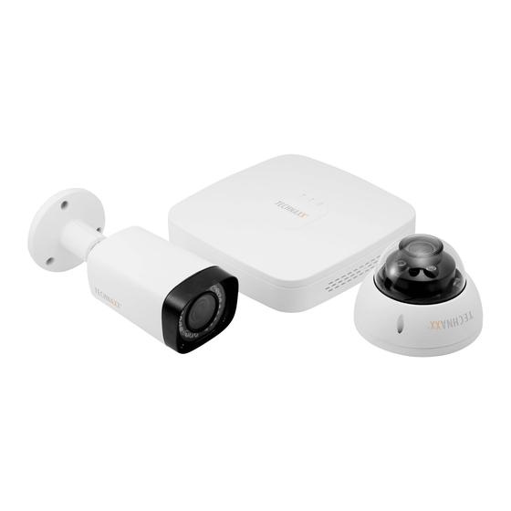
Midi Security Kit PRO FullHD
Table of Contents
1
FEATURES AND SPECIFICATIONS .......................................................................................... 7
1.1
Overview ................................................................................................................................................. 7
1.2
Features .................................................................................................................................................. 7
1.3
Specifications ......................................................................................................................................... 8
1.3.1
Midi Security Kit PRO FullHD1080P TX-51 .................... Fehler! Textmarke nicht definiert.
2
OVERVIEW AND CONTROLS .................................................................................................... 8
2.1
Front Panel ........................................................................................................................................... 10
2.1.1
Midi Security Kit PRO FullHD1080P TX-51 .................... Fehler! Textmarke nicht definiert.
2.2
Rear Panel ............................................................................................................................................ 10
2.2.1
Midi Security Kit PRO FullHD1080P TX-51 .................... Fehler! Textmarke nicht definiert.
2.3
Connection Sample ............................................................................................................................. 12
2.3.1
Midi Security Kit PRO FullHD1080P TX-51 .................... Fehler! Textmarke nicht definiert.
2.4
Remote Control .................................................................................................................................... 12
2.5
Mouse Control ...................................................................................................................................... 14
User Manual
1080P TX-51
i
Advertisement
Table of Contents

Related Manuals for Technaxx TX-51


Summary of Contents for Technaxx TX-51
-
Page 1: Table Of Contents
Features ..............................7 Specifications ............................8 1.3.1 Midi Security Kit PRO FullHD1080P TX-51 ....Fehler! Textmarke nicht definiert. OVERVIEW AND CONTROLS ....................8 Front Panel ............................10 2.1.1 Midi Security Kit PRO FullHD1080P TX-51 .... - Page 2 About Front Panel and Rear Panel ....................17 HDD Installation ........................... 17 3.3.1 Midi Security Kit PRO FullHD1080P TX-51 ....Fehler! Textmarke nicht definiert. Connecting Power Supply ........................18 Connecting Video Input and Output Devices .................. 18 ...
- Page 3 Right-Click Menu ..........................28 4.4.1 Window Switch ........................28 4.4.2 PTZ Control.......................... 28 4.4.3 Color ............................ 33 4.4.4 Search ..........................35 4.4.5 Manual Record ........................35 Navigation Bar ............................35 ...
- Page 4 4.10.4 Storage ..........................86 4.10.5 System ..........................96 WEB OPERATION........................108 Network Connection .......................... 108 Login ..............................108 LAN Mode ............................109 Live ..............................110 PTZ ..............................111 ...
- Page 5 5.11 Log out ..............................163 5.12 Un-install Web Control ........................163 6 PROFESSIONAL SURVEILLANCE SYSTEM ................. 164 FAQ ............................165 Important Safeguards and Warnings 1.Electrical safety All installation and operation here should conform to your local electrical safety codes. The product must be grounded to reduce the risk of electric shock.
- Page 6 (use a clean drapery). Avoid using rough, coarse-grained materials/solvents/other aggressive cleaner. Wipe the cleaned device. Important Notice: Should battery fluid leak from a battery, wipe the battery- case with a soft cloth dry. Distributor: Technaxx Deutschland GmbH & Co.KG, Kruppstr. 105, 60388 Frankfurt a.M., Germany...
-
Page 7: Features And Specifications
1 FEATURES AND SPECIFICATIONS 1.1 Overview This series product is an excellent digital monitor product designed for security field. It adopts embedded Linux OS to maintain reliable operation. It is easy to use and can realize surveillance function after some simple setups. It has various functions such as record, playback, monitor at the same time and can guarantee audio video synchronization. -
Page 8: Specifications
1.3 Specifications 1.3.1 Midi Security Kit PRO FullHD1080P TX-51 Parameters System Main Processor Industrial embedded micro controller Embedded LINUX Video Video Encode H.264 Parameters Standard Encode 1080P /720P/D1/HD1/2CIF/CIF/QCIF Resolution Video Frame PAL:1~25f/s;NTSC:1~30f/s Rate Video Frame 2048Kbps-6144Kbps, Rate For 1080P: default setup is 4Mbps,max supports 6Mbps... - Page 9 Parameters Bidirectional Talk Input Record Record Mode Schedule record/manual record/MD record/Alarm record Record Max 4-channel playback Playback Backup Mode HDD, burner, USB device, network backup Alarm Alarm Input Alarm Output HDD Port 1 SATA port,does not support eSATA port Space Coomunication Network 1 RJ45 port, 100Mbps Ethernet port...
-
Page 10: Overview And Controls
2.1 Front Panel There is no button on the front panel of the Smart Box. There is no need to introduce the front panel. 2.1.1 Midi Security Kit PRO FullHD1080P TX-51 The front panel is shown as below. See Figure 2-1. ... -
Page 11: Rear Panel
2.2 Rear Panel 2.2.1 Midi Security Kit PRO FullHD1080P TX-51 The rear panel of Midi Security Kit Pro TX-51 is shown as below. See Figure 2-2. Refer to the following sheet for detailed information. Figure 2-2 Icon Name Note... -
Page 12: Connection Sample
2.3 Connection Sample 2.3.1 Midi Security Kit PRO FullHD1080P TX-51 Refer to the following sheet for detailed information. Figure 2‐8 2.4 Remote Control (for all 3 receivers the same) The remote control interface is shown as in Figure 2-9. Note: remote control is not our standard accessory and it is not included in the accessory bag. - Page 13 Remote Contol Functions Serial Number Name Function Power button Click it to boot up or shut down the device. Address Click it to input device number, so that you can control Forward Various forward speeds and normal speed playback. Slow play Multiple slow play speeds or normal playback.
-
Page 14: Mouse Control
go to the menu Multiple- Switch between multiple-window and one-window. window switch Auxiliary key In 1-ch monitor mode: pop up assistant function:PTZ control and Video color. Switch the PTZ control menu in PTZ control interface. In motion detection interface, working with direction keys to complete setup. - Page 15 In input box, you can select input methods. Left click the corresponding button panel input numeral/English character (small/capitalized). Here ← stands for backspace button. _ stands for space button. In English input mode: _stands for input a backspace icon and ← stands for deleting the previous character.
- Page 16 Right click In real-time monitor mode, pops up shortcut menu: one-window, four-window, mouse nine-window and sixteen-window, Pan/Tilt/Zoom, color setting, search, record, alarm input, alarm output, main menu. Among which, Pan/Tilt/Zoom and color setting applies for current selected channel. If you are in multiple-window mode, system automatically switches to the corresponding channel.
-
Page 17: Installation And Connections
Follow the instructions below to install hard disk. All the figurers listed below are for reference only. Slight difference may be found on the front or rear panel. 3.3.1 Midi Security Kit PRO FullHD1080P TX-51 The series DVR has one SATA HDD. ... -
Page 18: Connecting Power Supply
7. Put the cover in accordance 8. Secure the screws in the with the clip and then place the rear panel and the side panel. upper cover back. Important: You can connect the HDD data cable and the power cable first and then fix the HDD in the device. -
Page 19: Connecting Video Output
Keep connection lugs in well contact B T T T B The signal line and shielded wire should be fixed firmly and in well connection. Avoid dry joint, lap welding and oxidation. B T T T B 3.5.2 Connecting Video Output Video output includes a BNC(PAL/NTSC1.0V ,75Ω)output ,a VGA output and HDMI output. -
Page 20: Alarm Output Port
The alarm output port should not be connected to high power load directly (It shall be less than 1A) to avoid high current which may result in relay damage. Use the co contactor to realize the connection between the alarm output port and the load. 3. -
Page 21: Other Interfaces
3ms max Length of close time Longevity Mechanical 50×106 times (3Hz) Electrical 200×103 times (0.5Hz) Temperature ~+70 3.8 Other Interfaces There are still other interfaces on the DVR, such as USB port. -
Page 22: Overview Of Navigation And Controls
4 Overview of Navigation and Controls 4.1 Boot up and Shutdown 4.1.1 Boot up Before the boot up, make sure: The rated input voltage matches the device power on-off button. Make sure the power wire connection is OK. Then click the power on-off button. ... - Page 23 Tips: Check the box Startup button here, system goes to startup wizard again when it boots up the next time. Cancel the Startup button, system goes to the login interface directly when it boots up the next time. Figure 4‐1 Click Cancel button or Next Step button, system goes to login interface. See Figure 4-2. System consists of four accounts: ...
- Page 24 Click OK button, you can go to General interface. See Figure 4-3. For detailed information, refer to chapter 4.10.5.1. Figure 4-3 Click Next button, you can go to network interface. See Figure 4-4. For detailed information, refer to chapter 4.9.3. Figure 4-4 Click Next button, you can go to Schedule interface.
-
Page 25: Manual Record
Figure 4-5 Click Finish button, system pops up a dialogue box. Click the OK button, the startup wizard is complete. See Figure 4-6. Figure 4-6 4.3 Manual Record 4.3.1 Live Viewing After you logged in, the system is in live viewing mode. You can see system date, time, channel name and window No. - Page 26 Tips Preview drag: If you want to change position of channel 1 and channel 2 when you are previewing, you can left click mouse in the channel 1 and then drag to channel 2, release mouse you can switch channel 1 and channel 2 positions. Use mouse middle button to control window split: You can use mouse middle button to ...
- Page 27 There are two ways for you to zoom in. Drag the mouse to select a zone, you can view an interface show as Figure 4-9. Figure 4-9 Put the middle button at the centre of the zone you want to zoom in, and move the mouse, you can view an interface shown as in Figure 4-10.
-
Page 28: Right-Click Menu
4.4 Right-Click Menu On the preview interface, right click mouse, you can view menu interface shown as in Figure 4-11. Tips After you go to the corresponding interface, right click mouse to go back to the upper-level. Figure 4-11 4.4.1 Window Switch System supports 1/4-window. - Page 29 Figure 4‐13 In the middle of the eight direction arrows, there is a 3D intelligent positioning key. See Figure 4-14. Make sure your protocol supports this function and you need to use mouse to control. Click this key, system goes back to the single screen mode. Drag the mouse in the screen to adjust section size.
- Page 30 Icon Function Icon Function Preset Flip Tour Reset Pattern Scan on-off button Rotate Go to menu 4.4.2.1 PTZ Function Setup Click , you can go to the following interface to set preset, tour, pattern, and scan. See Figure 4-16. Figure 4‐16 Preset Setup In Figure 4-16, click preset button and use eight direction arrows to adjust camera to the proper position.
- Page 31 Figure 4‐17 Tour Setup In Figure 4-16, click tour button. Input tour value and preset No. Click Add preset button to add current preset to the tour. See Figure 4-18. Tips Repeat the above steps to add more presets to the tour. Click Del preset button to remove it from the tour.
- Page 32 Figure 4‐19 Scan Setup In Figure 4-16, click Scan button. Use direction buttons to set camera left limit and then click Left button. Use direction buttons to set camera right limit and then click Right button. Now the scan setup process is complete. Figure 4‐20 ...
-
Page 33: Color
In Figure 4-15, input Scan value and then click to call a tour. Click again to stop call. Rotate In Figure 4-15, click to enable the camera to rotate. System supports preset, tour, pattern, scan, rotate, light and etc function. Note: ... - Page 34 Refer to the following sheet for detailed information. Item Note Period There are two periods in one day. You can set different sharpness, brightness, and contrast setup for different periods. Effective Time Check the box here to enable this function and then set period time.
-
Page 35: Search
Item Note Position It is to adjust the image position on the screen. Customized Click it to set customized color mode. 4.4.4 Search Refer to chapter 4.8.1 for detailed information. 4.4.5 Manual Record Refer to chapter 4.10.4.3.1 for detailed information. 4.5 Navigation Bar You need to go to the Main menu->Setting->System->General to enable navigation bar function;... -
Page 36: Color
4.5.6 Color Click button , system goes to the color interface. refer to chapter 4.4.3. 4.5.7 Search Click button , system goes to search interface. Refer to chapter 4.8.1 4.5.8 Alarm Status Click button , system goes to alarm status interface. It is to view device status and channel status. -
Page 37: Usb Manager
4.5.13 USB Manager Click , system goes to the USB Manager interface. It is to view USB information, backup and update. Refer to chapter 4.8.2, chapter 4.9.4, chapter 4.10.5.7, and chapter 4.10.5.9 for detailed information. 4.6 USB Device Auto Pop-up After you inserted the USB device, system can auto detect it and pop up the following dialogue box. - Page 38 Figure 4-28 Refer to the following sheet for more information. Name Function Display Here is to display the searched picture or file. Support 1/4/8-window playback. window Here you can select to search the picture or the recorded file. You can select to play from the read-write HDD, from peripheral device or from redundancy HDD.
- Page 39 Click it to go to mark file list interface. You can view all mark information of current Mark file channel by time. Refer to chapter 4.8.1.3 for detailed information. Note only the list button product of this icon supports mark function. Double click it, you can view the picture/record file list of current day.
- Page 40 play 1,fast play 2 and etc. Note: The actual play speed has relationship with the software version. Smart search The volume of the playback Click the snapshot button in the full-screen mode, the system can snapshot 1 picture. System supports custom snap picture saved path. Connect the peripheral device first, click snap button on the full-screen mode, you can select or create path.
- Page 41 After you set, you can click Clip button again to edit the second period. You can see the slide bar restore its previous position. Click Backup button after clip, you can save current contents in a new file. You can clip for one channel or multiple-channel. The multiple-channel click operation is similar with the one-channel operation.
- Page 42 Figure 4‐29 Click the , you can go to the smart search playback. Click it again, system stops smart search playback. Important System does not support motion detect zone setup during the full-screen mode. During the multiple-channel playback, system stops playback of rest channels if you implement one-channel smart search.
- Page 43 Figure 4‐30 4.8.1.3 Mark Playback Make sure your purchased device support this function. You can use this function only if you can see the mark playback icon on the Search interface (Figure 4-28). When you are playback record, you can mark the record when there is important information. After playback, you can use time or the mark key words to search corresponding record and then play.
-
Page 44: Backup
Figure 4-32 Modify Double click one mark information item, you can see system pops up a dialogue box for you to change mark information. You can only change mark name here. Delete Here you can check the mark information item you want to delete and then click Delete button, you can remove one mark item. - Page 45 Figure 4‐33 Select backup device and then set channel, file start time and end time. Click add button, system begins search. All matched files are listed below. System automatically calculates the capacity needed and remained. See Figure 4-35. Figure 4‐34 System only backup files with a √ before channel name. You can use Fn or cancel button to delete √...
-
Page 46: Shut Down
Figure 4‐35 When the system completes backup, you can see a dialogue box prompting successful backup. File format: Click the file format; you can see there are two options: DAV/ASF. The file name format usually is: Channel number+Record type+Time. In the file name, the YDM format is Y+M+D+H+M+S. -
Page 47: Information
For the user who does not have the shut down right, input corresponding password to shut down. Figure 4‐36 4.9 Information It is for you to view sysem info, event info, and network info and log info. 4.9.1 System Info Here is for you to view system information. - Page 48 Figure 4‐38 Double click one HDD information; you can see the HDD SMART information. See Figure 4-39. Figure 4‐39 4.9.1.2 Record Info It is to view record start time and end time. See Figure 4-40. Figure 4‐40 ...
- Page 49 4.9.1.3 BPS Here is for you to view current video data stream (KB/s), resolution and etc. See Figure 4‐41 . Figure 4‐41 4.9.1.4 Version Here is for you to view some version information such as version number, built date, serial number and etc.
-
Page 50: Event
4.9.2 Event It is to display device status and channel status. See Figure 4-43. Figure 4‐43 4.9.3 Network 4.9.3.1 Online Users Here is for you to manage online users. See Figure 4-44. You can disconnect one user or block one user if you have proper system right. Max disconnection setup is 65535 seconds. - Page 51 4.9.3.2 Network Load Network load is shown as in Figure 4-45. Here you can view the follow statistics of the device network adapter. Here you can view information of all connected network adapters. The connection status is shown as offline if connection is disconnected. Click one network adapter, you can view the flow statistics such as send rate and receive rate at the top panel.
-
Page 52: Log
Figure 4‐46 4.9.4 Log Here is for you to view system log file. System lists the following information. See Figure 4-47. Log types include system operation, configuration operation, data management, alarm event, record operation, account manager, log clear, file operation and etc. It optimized reboot log. There are only three types: normal reboot, abnormal reboot and protection reboot. -
Page 53: Setting
Select an item on the list and then click the Details button or double click the log item, you can view the detailed information such as log time, log type, log user, IP address and etc. See Figure 4-48. Figure 4‐48 4.10 Setting It is for you to set camera, network, event, storage, system and etc. - Page 54 Delete: Select one device in the Added device list and then click to remove. Status: means connection is OK and means connection failed. Delete;Select a device on the Added device list, click Delete button, system disconnect device first and then remove its name from the list. ...
- Page 55 4.10.1.1.2 Channel Status Here you can view the IPC status of the corresponding channel such as motion detect, video loss, tampering, alarm and etc. See Figure 4-51. IPC status : : Front-end does not support. : Front-end supports. : There is alarm event from current front-end.
- Page 56 4.10.1.1.4 Remote Upgrade It is to update the camera. From main menu->setting->camera->remote, the interface is shown as below. See Figure 4-53. Click Browse button and then select the upgrade file. Then select a channel (or you can select device type filter to select several devices at the same time.) Click Start upgrade button to update.
- Page 57 WDR: For the WDR scene, this function can lower the high bright section and enhance the brightness of the low bright section. So that you can view these two sections clearly at the same time. The value ranges from 1 to 100. When you switch the camera from no-WDR mode to the WDR mode, system may lose several seconds record video.
- Page 58 Figure 4‐55 4.10.1.3 Encode It is to set video bit stream, picture bit stream, video overlay parameter and etc. 4.10.1.3.1 Video Video setting includes the following items. See Figure 4-56. Channel: Select the channel you want. Type: Select from the dropdown list. There are three options: regular/motion detect/alarm. ...
- Page 59 Figure 4‐56 4.10.1.3.2 Snapshot Here you can set snapshot mode, picture size, quality and frequency. See Figure 4-57. Snapshot mode: There are two modes: regular and trigger. If you set timing mode, you need to set snapshot frequency. If you set trigger snapshot, you need to set snapshot activation operation.
- Page 60 4.10.1.3.3 Overlay Overlay interface is shown as in Figure 4-58. Cover area: Here is for you to set cover area. You can drag you mouse to set proper section size. In one channel video, system max supports 4 zones in one channel. ...
-
Page 61: Network
4.10.1.3.4 Channel Name It is to modify channel name. It max supports 31-character. See Figure 4-60. Figure 4‐60 4.10.1.3.5 Channel Type It is to set channel type. It supports coaxial/UTP. See Figure 4-61. Figure 4‐61 4.10.2 Network 4.10.2.1 TCP/IP The interface is shown as in Figure 4-62 IP Version: There are two options: IPv4 and IPv6. - Page 62 IP address: Here you can use up/down button () or input the corresponding number to input IP address. Then you can set the corresponding subnet mask the default gateway. Default gateway: Here you can input the default gateway. Note system needs to check the validity of all IPv6 addresses.
- Page 63 HTTPS port: Default value is 443. RTSP port: Default value is 554. Important: System needs to reboot after you changed and saved any setup of the above four ports. Make sure the port values here do not conflict. Figure 4‐63 ...
- Page 64 WIFI working status: Here you can view current connection status. Note: After successful connection, you can see WIFI connection icon at the top right corner of the preview interface. When the hotspot verification type is WEP, system displays as AUTO since the device can ...
- Page 65 4.10.2.5 PPPoE PPPoE interface is shown as in Figure 4-66. Input “PPPoE name” and “PPPoE password” you get from your ISP (Internet service provider). Click save button, you need to restart to activate your configuration. After rebooting, DVR will connect to internet automatically. The IP in the PPPoE is the DVR dynamic value.
- Page 66 Figure 4‐67 Note NNDS type includes: CN99 DDNS, NO-IP DDNS, Dahua DDNS, Dyndns DDNS and sysdns DDNS. All the DDNS can be valid at the same time, you can select as you requirement. Private DDNS function shall work with special DDNS server and special Professional Surveillance Software (PSS).
- Page 67 User name: It is optional. You can input your commonly used email address. Important Do not register frequently. The interval between two registrations shall be more than 60 seconds. Too many registration requests may result in server attack. ...
- Page 68 Figure 4‐68 Figure 4‐69 4.10.2.8 Email The email interface is shown as below. See Figure 4-70. SMTP server: Input your email SMTP server IP here. Port: Input corresponding port value here. User name: Input the user name to login the sender email box. ...
- Page 69 according to the interval you specified here. This function is very useful when there are too many emails activated by the abnormity events, which may result in heavy load for the email server. Figure 4‐70 4.10.2.9 FTP You need to download or buy FTP service tool (such as Ser-U FTP SERVER) to establish FTP service.
- Page 70 Figure 4‐72 System also supports upload multiple DVRs to one FTP server. You can create multiple folders under this FTP. FTP interface is shown as in Figure 4-73. Highlight the icon in front of Enable to activate FTP function. Here you can input FTP server address, port and remote directory. When remote directory is null, system automatically create folders according to the IP, time and channel.
- Page 71 4.10.2.10 UPnP The UPNP protocol is to establish a mapping relationship between the LAN and the WAN. Input the router IP address in the LAN in Figure 4-62. See Figure 4-74. UPNP on/off :Turn on or off the UPNP function of the device. ...
- Page 72 Figure 4‐75 4.10.2.11 SNMP SNMP is an abbreviation of Simple Network Management Protocol. It provides the basic network management frame of the network management system. The SNMP widely used in many environments. It is used in many network device, software and system. You can set in the following interface.
- Page 73 Input the device IP you want to manage in the MG-SOFT MIB Browser. Set the corresponding version for your future reference. Open the tree list on the MG-SOFT MIB Browser; you can get the device configuration. Here you can see the device has how many video channels, audio channels, application version and etc.
- Page 74 Administrative scoped addressees -239.0.0.0-239.255.255.255 -Private address space Like the single broadcast address of RFC1918 Can not be used in Internet transmission Used for multiple cast broadcast in limited space. Except the above mentioned addresses of special meaning, you can use other addresses. For example: Multiple cast IP: 235.8.8.36 Multiple cast PORT: 3666.
- Page 75 2) The proxy server software developed from the SDK. Open the software and input the global setup. Make sure the auto connection port here is the same as the port you set in the previous step. 3) Now you can add device. Do not input default port number such as the TCP port in the mapping port number.
-
Page 76: Event
4.10.3 Event 4.10.3.1 Detect In the main menu, from Setting->Event->Detect, you can see motion detect interface. See Figure 4-81.There is three detection types: motion detection, video loss, tampering. The video loss has no detection region and sensitivity setup and tampering has no detection region setup. - Page 77 Alarm output: when an alarm occurs, system enables peripheral alarm devices. Latch: when motion detection complete, system auto delays detecting for a specified time. The value ranges from 1-300(Unit: second) Show message: System can pop up a message to alarm you in the local host screen if you enabled this function.
- Page 78 Figure 4‐82 Figure 4‐83 Figure 4‐84 Figure 4‐85 ...
- Page 79 Motion detect here only has relationship with the sensitivity and region setup. It has no relationship with other setups. 4.10.3.1.2 Video Loss In Figure 4-81, select video loss from the type list. You can see the interface is shown as in Figure 4-86.This function allows you to be informed when video loss phenomenon occurred.
- Page 80 Note: In Detect interface, copy/paste function is only valid for the same type, which means you can not copy a channel setup in video loss mode to tampering mode. About Default function. Since detection channel and detection type may not be the same, system can only restore default setup of current detect type.
- Page 81 Alarm in: Here is for you to select channel number. Type: normal open or normal close. PTZ activation: Here you can set PTZ movement when alarm occurs. Such as go to preset, tour& pattern when there is an alarm. Click “select” button, you can see an interface is shown as in Figure 4-92.
- Page 82 Figure 4-88 Figure 4‐89 . Figure 4-90...
- Page 83 Figure 4‐91 Figure 4‐92 Figure 4‐93 Figure 4‐94 ...
- Page 84 4.10.3.3 Abnormality There are two types: HDD/Network. HDD: HDD error, no disk, no space. See Figure 4-95 and Figure 4-96. Network: Disconnection, IP conflict, MAC conflict. See Figure 4-97. Alarm output: Select alarm activation output port (multiple choices). ...
- Page 85 Figure 4‐97 4.10.3.4 Alarm Output Here is for you to set proper alarm output such as schedule, manual. Highlight icon to select the corresponding alarm output. After all the setups click OK button, system goes back to the previous menu. See Figure 4-98. Figure 4-98 ...
- Page 86 4.10.4 Storage It is to set HDD management, storage parameters, set record plan and record control. 4.10.4.1 Schedule It is for you to set record plan and snapshot plan. 4.10.4.1.1 Record Note: You need to have proper rights to implement the following operations. Make sure the HDDs have been properly installed.
- Page 87 Figure 4-101 Highlight icon to select the corresponding function. After completing all the setups click save button, system goes back to the previous menu. There are color bars for your reference. Green color stands for regular recording, yellow color stands for motion detection and red color stands for alarm recording.
- Page 88 Figure 4-103 4.10.4.1.1.1 Quick Setup Copy function allows you to copy one channel setup to another. After setting in channel 1, click Copy button, you can go to interface Figure 4-104. You can see current channel name is grey such as channel 1.
- Page 89 Note About redundancy setup: If current channel is not recording, current setup gets activated when the channel begin recording the next time. If current channel is recording now, current setup will get activated right away, the current file will be packet and form a file, then system begins recording as you have just set.
- Page 90 Figure 4‐106 Figure 4‐107 4.10.4.1.2.2 Trigger Snapshot Follow the steps listed below to enable the activation snapshot function. After you enabled this function, system can snapshot when the corresponding alarm occurred. In main menu, from Setting->Camera->Encode->Snapshot interface, here you can input snapshot mode as trigger, size, quality and frequency.
- Page 91 Figure 4‐108 Figure 4-109 4.10.4.1.2.3 Priority Note the activation snapshot has the higher priority than schedule snapshot. If you have enabled these two types at the same time, system can activate the activation snapshot when alarm occurs, and otherwise system just operates the schedule snapshot. 4.10.4.1.2.4 Image FTP In the main menu, from Setting->Network->FTP, you can set FTP server information.
- Page 92 Input the corresponding information here, if you just upload the image FTP. Figure 4‐110 4.10.4.2 HDD Manager Here is for you to view and implement hard disk management. See Figure 4-111. You can see current HDD type, status, capacity and etc. The operation includes format HDD, and change HDD property (read and write/read-only/redundancy).
- Page 93 In live viewing mode, click record button in the front panel or record button in the remote control. System supports main stream stream. There three statuses: schedule/manual/stop. See Figure 4-112. Highlight icon “ ○ ” to select corresponding channel. ...
- Page 94 Tips You can check All button after the corresponding status to enable/disable all-channel snapshot function. 4.10.4.4 HDD Detect The HDD detect function is to detect HDD current status so that you can clearly understand the HDD performance and replace the malfunction HDD. There are two detect types: ...
- Page 95 4.10.4.4.2 Detect Report After the detect operation, you can go to the detect report to view corresponding information. The detect report interface is shown as below. See Figure 4-116. Figure 4‐116 Click the item you can see the detailed information such as detect result. See Figure 4-117. Figure 4‐117 ...
- Page 96 4.10.5 System 4.10.5.1 General 4.10.5.1.1 Device General setting includes the following items. See Figure 4-118. Device ID: Input a corresponding device name here. Device No: Here you can set device number. Language: System supports various languages: Chinese (simplified), Chinese (Traditional), English, Italian, Japanese, French, Spanish (All languages listed here are optional.
- Page 97 Figure 4‐119 4.10.5.1.3 Holiday Holiday setup interface is shown as in Figure 4-120. Click Add new holiday button, you can input new holiday information. See Figure 4-121. Here you can set holiday name, repeat mode and start/end time. Note When you enable Holiday settings and schedule setup at the same time, holiday setting has the priority.
- Page 98 Figure 4‐121 4.10.5.2 Display It is to set display, TV adjust, tour, zero-channel encode, and preview favorites information. 4.10.5.2.1 Display Display setup interface is shown as below. See Figure 4-122. Transparency: Here is for you to adjust transparency. The value ranges from 128 to 255. ...
- Page 99 4.10.5.2.2 Tour Here you can activate tour function. Click Setup button, you can see an interface shown as in Figure 4-123 Enable tour: Highlight box here to enable this function. Interval: System supports 1/8-window tour. Input proper interval value here. The value ranges from 5-120 seconds.
- Page 100 select zero-channel encoding mode right corner interface . Select a mode; you can view the local preview video. Figure 4‐124 4.10.5.2.4 Favorites It is for you to set and save favorites preview setup. You can select different window display modes and then select corresponding channel(s). Note for one mode, one channel can only be selected once.
- Page 101 Figure 4-126 4.10.5.3 PTZ The pan/tilt/zoom setup includes the following items. Select channel first. See Figure 4-127. PTZ type: There are two options: local/remote. Select remote if you are connecting to the network PTZ. See Figure 4‐128. Control mode: You can select control mode from the dropdown list. There are two options: Serial/HDCVI.
- Page 102 4.10.5.4 ATM/POS The ATM/POS function is for financial areas. It includes Sniffer, information analysis and title overlay function. The Sniffer mode is network. The network type interface is shown as below. See Figure 4-129. Here we take the ATM/POS protocol to continue. There are two types: with or without the protocol according to client’s requirements.
- Page 103 4.10.5.5 Account Here is for you to implement account management. See Figure 4-131 and Figure 4-132. Here you can: Add new user Modify user Add group Modify group Modify password. For account management note: For the user account name and the user group, the string max length is 6-byte.
- Page 104 Figure 4-132 4.10.5.5.1 Add/Modify Group Click add group button in Figure 4-132 , the interface is shown as below. See Figure 4-133. Here you can input group name and then input some memo information if necessary. There are total 98 rights such as control panel, shut down, real-time monitor, playback, record, record file backup, PTZ, user account, system information view, alarm input/output setup, system setup, log view, clear log, upgrade system, control device and etc.
- Page 105 Figure 4‐134 When you create a new user, you can input the corresponding MAC address of current user. If you leave this item in blank, any MAC address user can share this user account to login. Note system needs to check the validity of MAC. Only the 12-digit 0-f format address can pass the validity verification.
- Page 106 Format: Click Format button, system pops up a dialogue box for you to confirm current operation. System begins format process after you click the OK button. Note: System can not open config backup interface again if there is backup operation in the process.
- Page 107 4.10.5.9 Update Here is for you to view hardware features, software version, built date, release SN information and etc. You can also update system here. See Figure 4-138. Start: Insert the USB device that have the update file to the device and then click the Start button to begin the update.
- Page 108 5 WEB OPERATION Slightly difference may be found in the interface due to different series. 5.1 Network Connection Before web client operation, check the following items: Network connection is right DVR and PC network setup is right. Refer to network setup(main menu->Setting->Network) ...
- Page 109 5.3 LAN Mode For the LAN mode, after you logged in, you can see the main window. See Figure 5-3. Figure 5‐3 This main window can be divided into the following sections. Section 1: there are six function buttons: Live(chapter 5.4), playback (chapter 5.9) setup (chapter 5.8), info (chapter 5.8.6), alarm (chapter 5.10), and logout (chapter 0).
- Page 110 Figure 5‐6 Section 4: Instant record button. Click it, the button becomes yellow and system begins manual record. See Figure 5-7. Click it again, system restores previous record mode. Figure 5‐7 Section 5: Local play button. The Web can playback the saved (Extension name is dav) files in the PC-end. Click local play button, system pops up the following interface for you to select local play file.
- Page 111 1 2 3 4 Figure 5-9 On the top right corer, there are six unction buttons. See Figure 5-10. 1 2 3 4 5 Figure 5-10 1: Digital zoom: Click this button and then left drag the mouse in the zone to zoom in. right click mouse system restores original status. ...
- Page 112 Parameter Function Select Pattern from the dropdown list. Pattern You can input pattern value and then click Start button to begin PTZ movement such as zoom, focus, iris, direction and etc. Then you can click Add button to set one pattern. Input the corresponding aux value here.
- Page 113 Figure 5-12 5.7 WAN Login In WAN mode, after you logged in, the interface is shown as below. See Figure 5-13. Figure 5‐13 Refer to the following contents for LAN and WAN login difference. 1) In the WAN mode, system opens the main stream of the first channel to monitor by default. The open/close button on the left pane is null.
- Page 114 Figure 5‐14 Important The window display mode and the channel number are by default. For example, for the 16- channel, the max window split mode is 16. 3) Multiple-channel monitor, system adopts extra stream to monitor by default. Double click one channel, system switches to single channel and system uses main stream to monitor.
- Page 115 Figure 5‐15 Figure 5‐16 Refer to the following sheet for log parameter information. Parameter Function Click Device search button, you can view the searched device Device information on the list. It includes device IP address, port, device search name, manufacturer and type. Select a device in the list and then click Add button, system can connect the device automatically and add it to the Added device list.
- Page 116 Parameter Function Click it, the interface is shown as in Figure 5-16. Here you can add Manual network camera manually. You can select a channel from the dropdown list (Here only shows disconnection channel.) Note: System supports manufactures such as Panasonic, Sony, Dynacolor, Samsung, AXIS, Arecont, Dahua and Onvif standard protocol.
- Page 117 Period It divides one day (24 hours) to two periods. You can set different hue, brightness, and contrast for different periods. It is to adjust monitor video brightness and darkness level. The default value is 50. The bigger the value is, the large the contrast between the bright and dark section is and vice versa.
- Page 118 Mode For the WDR scene, this function can lower the high bright section and enhance the brightness of the low bright section. So that you can view these two sections clearly at the same time. The value ranges from 1 to 100. When you switch the camera from no-WDR mode to the WDR mode, system may lose several seconds record video.
- Page 119 Figure 5‐19 Refer to the following sheet for detailed information. Parameter Function Channel Select a channel from the dropdown list. Video Check the box here to enable extra stream video. This item is enable enabled by default. Code It includes main stream, motion stream and alarm stream. You can stream type select different encode frame rates form different recorded events.
- Page 120 Select from the dropdown list. There are two options: Audio Normal/HDCVI. In the normal mode, the audio signal comes source from the Audio In. In the HDCVI mode, the audio signal comes from the coaxial cable of the camera. This function allows you to verify the video is tampered or not. Watermark enable Here you can select watermark bit stream, watermark mode and...
- Page 121 Figure 5‐21 Refer to the following sheet for detailed information. Parameter Function Cover-area Check Preview or Monitor first. Click Set button, you can privacy mask the specified video in the preview or monitor video. System max supports 4 privacy mask zones. Time Title You can enable this function so that system overlays time information in video window.
- Page 122 Figure 5‐23 5.8.2 Network 5.8.2.1 TCP/IP The TCP/IP interface is shown as in Figure 5-24. Figure 5‐24 Refer to the following sheet for detailed information. Parameter Function Mode There are two modes: static mode and the DHCP mode. The IP/submask/gateway are null when you select the DHCP mode to auto search the IP.
- Page 123 For the IP address of IPv6 version, default gateway, preferred DNS and alternate DNS, the input value shall be 128-digit. It shall not be left in blank. System can process the downloaded data first if you enable LAN load this function. The download speed is 1.5X or 2.0X of the normal speed.
- Page 124 5.8.2.4 WIFI Note this function is for the device of WIFI module. The WIFI interface is shown as in Figure 5-27. Figure 5‐27 Check the box to enable WIFI function and then click the Search SSID button. Now you can view all the wireless network information in the following list.
- Page 125 you close the extra stream monitor. Pulse interval here is for extra stream only. This item is null if you are using main stream to monitor. 5.8.2.5.2 Mobile The mobile setup interface is shown as in Figure 5-29. Here you can activate (send out “on”) or turn off (Send out “off”) the 3G connected phone or mobile phone, or the phone you set to get alarm message.
- Page 126 The DDNS is to set to connect the various servers so that you can access the system via the server. Go to the corresponding service website to apply a domain name and then access the system via the domain. It works even your IP address has changed. Select DDNS from the dropdown list (Multiple choices).
- Page 127 default domain name (Generated by MAC address) for your option. You can also use customized valid domain name (has not registered.). 3) Operation Before you use Dahua DDNS, you need to enable this service and set proper server address, port value and domain name. ...
- Page 128 Figure 5‐33 Refer to the following sheet for detailed information. Parameter Function Check the box here to enable email function. Enable Input server address and then enable this function. SMTP Server Port Default value is 25. You can modify it if necessary. Anonymity For the server supports the anonymity function.
- Page 129 Parameter Function This function allows the system to send out the test email to Update period check the connection is OK or not. Check the box to enable (interval) this function and then set the corresponding interval. System can send out the email regularly as you set here. The system will automatically sent out a email once to test the Email test connection is OK or not .Before the email test, save the email...
- Page 130 Figure 5‐35 Refer to the following sheet for detailed information. Parameter Function Check the corresponding box to enable PAT function. Status Dsiplay UPnP function status. It is corresponding to the UPnP mapping information on the router. Check the box before the service name to enable current PAT service. Otherwise, the service is null.
- Page 131 5.8.2.12 SNMP The SNMP interface is shown as in Figure 5-36. The SNMP allows the communication between the network management work station software and the proxy of the managed device. It is reserved for the 3 party to develop. Figure 5‐36 Refer to the following sheet for detailed information.
- Page 132 5.8.2.13 Multicast The multicast interface is shown as in Figure 5-37. Multicast is a transmission mode of data packet. When there is multiple-host to receive the same data packet, multiple-cast is the best option to reduce the broad width and the CPU load. The source host can just send out one data to transit.
- Page 133 5.8.2.16 HTTPS In this interface, you can set to make sure the PC can successfully login via the HTTPS. It is to guarantee communication data security. The reliable and stable technology can secure the user information security and device safety. See Figure 5-40. Note ...
- Page 134 Figure 5‐43 Click Open button, you can go to the following interface. See Figure 5-44. Figure 5‐44 Click Install certificate button, you can go to certificate wizard. See Figure 5-45. Figure 5‐45 Click Next button to continue. Now you can select a location for the certificate. See Figure 5-46.
- Page 135 Figure 5‐46 Click Next button, you can see the certificate import process is complete. See Figure 5-47. Figure 5‐47 Click Finish button, you can see system pops up a security warning dialogue box. See Figure 5-48. Figure 5‐48 Click Yes button, system pops up the following dialogue box, you can see the certificate download is complete.
- Page 136 5.8.2.16.3 View and set HTTPS port From Setup->Network->Connection, you can see the following interface. See Figure 5-50. You can see HTTPS default value is 443. Figure 5‐50 5.8.2.16.4 Login Open the browser and then input https://xx.xx.xx.xx:port. xx.xx.xx.xx: is your device IP or domain mane. Port is your HTTPS port.
- Page 137 Figure 5‐53 Figure 5‐54 Refer to the following sheet for detailed information. Parameter Function Enable You need to check the box to enable motion detection function. Select a channel from the dropdown list. Period Motion detection function becomes activated in the specified periods.
- Page 138 Parameter Function button to exit current setup. Do remember click save button to save current setup. If you click ESC button to exit the region setup interface system will not save your zone setup. Record System auto activates motion detection channel(s) to record once channel an alarm occurs.
- Page 139 5.8.3.1.1 motion detect for detailed information. Figure 5‐55 5.8.3.1.3 Tampering The tampering interface is shown as in Figure 5-56. After analysis video, system can generate a tampering alarm when the detected moving signal reached the sensitivity you set here. For detailed setups, refer to chapter 5.8.3.1.1 motion detect for detailed information. Figure 5‐56 ...
- Page 140 Figure 5‐57 Figure 5‐58 Figure 5‐59 Refer to the following sheet for detailed information. Parameter Function Enable You need to check the box to enable this function. Select a channel from the dropdown list. Period This function becomes activated in the specified periods.
- Page 141 Parameter Function There are six periods in one day. Draw a circle to enable corresponding period. Select date. If you do not select, current setup applies to today only. You can select all week column to apply to the whole week. Click OK button, system goes back to local alarm interface, click save button to exit.
- Page 142 Figure 5‐60 5.8.3.3 Abnormality It includes two types: No disk, disk error, disk no space, net disconnection, IP conflict and MAC conflict. See Figure 5-61 and Figure 5-62. Figure 5‐61 Figure 5‐62 Refer to the following sheet for detailed information. Parameter Function Event The abnormal events include: No disk, disk error, disk no space, net Type disconnection, IP conflict and MAC conflict.
- Page 143 Parameter Function Show System can pop up a message to alarm you in the local host screen if message you enabled this function. Alarm System can upload the alarm signal to the centre (Including alarm upload centre. Send If you enabled this function, System can send out an email to alert you Email when an alarm occurs.
- Page 144 Figure 5‐65 Refer to the following sheet for detailed information. Parameter Function Channel Select a channel from the dropdown list. Pre-record Input pre-record time here. The value ranges from 0 to 30. Redundancy Check the box here to enable redundancy function. Note this function is null if there is only one HDD.
- Page 145 Figure 5‐66 5.8.4.3 Record The interface is shown as in Figure 5-67. Figure 5‐67 Refer to the following sheet for detailed information. Parameter Function Here you can view channel number. Channel The number displayed here is the max channel amount of your device. Status There are three statuses: schedule, manual and stop.
- Page 146 5.8.5 Setting 5.8.5.1 General The general interface includes general, date/time and holiday setup. 5.8.5.1.1 General The general interface is shown as in Figure 5-68. Figure 5‐68 Refer to the following sheet for detailed information. Parameter Function It is to set device name. Device ID Device No.
- Page 147 Refer to the following sheet for detailed information. Parameter Function Here you can select date format from the dropdown list. Date format There are two options: 24-H and 12-H. Time Format The time zone of the device. Time zone It is to set system time. It becomes valid after you set. System time Sync PC...
- Page 148 5.8.5.2 Display Display interface includes GUI, TV adjust, Tour and zero-channel encoding. 5.8.5.2.1 Display Here you can set background color and transparency level. See Figure 5-71. Figure 5‐71 Refer to the following sheet for detailed information. Parameter Function There four options: Resolution 1920×1080,1280×1024(default),1280×720,1024×768.
- Page 149 Parameter Function Check the box here to enable tour function. Enable tour Here is for you to adjust transparency. The value ranges from 5 to Interval 120s. The default setup is 5s. Here you can set window mode and channel group. System can Split support 1/4/8-window according to device channel amount.
- Page 150 Figure 5‐74 Refer to the following sheet for detailed information. Parameter Function Select speed dome connected channel. Channel There are two options: local/remote. PTZ type You can select control mode from the dropdown list. There are two Control options: Serial/HDCVI. For HDCVI series product, select HDCVI. The mode control signal is sent to the PTZ via the coaxial cable.
- Page 151 With the protocol For ATM/POS with the protocol, you just need to set the source IP, destination IP (sometimes you need to input corresponding port number). Figure 5‐75 Without the protocol For the ATM/POS without the protocol, the interface is shown as in Figure 5-76. Source IP refers to host IP address that sends out information (usually it is the device host.) Destination IP refers to other systems that receive information.
- Page 152 The user amount default setup is 64 and the group amount default setup is 20. The factory default setup includes two levels: user and admin. You can set the corresponding group and then set the rights for the respective user in the specified groups. ...
- Page 153 Modify user It is to modify the user property, belonging group, password and rights. See Figure 5-79. Modify password It is to modify the user password. You need to input the old password and then input the new password twice to confirm the new setup. Click the OK button to save. Note, the password ranges from 1-digit to 6-digit.
- Page 154 Add group: It is to add group and set its corresponding rights. See Figure 5-81. Input the group name and then check the box to select the corresponding rights. It includes: shutdown/reboot device, live view, record control, PTZ control and etc. Figure 5‐81 ...
- Page 155 If you want to use the auto delete old files function, you need to set the file period. Click Manual reboot button, you can restart device manually. Figure 5‐83 5.8.5.7 Import/Export The interface is shown as in Figure 5-84. Figure 5‐84 Refer to the following sheet for detailed information. Parameter Function It is to import the local setup files to the system.
- Page 156 Figure 5‐86 5.8.6 Info 5.8.6.1 Version The version interface is shown as in Figure 5-87. Here you can view record channel, alarm input/output information, software version, release date and etc. Note the following information is for reference only. Figure 5‐87 5.8.6.2 Log Here you can view system log.
- Page 157 Parameter Function Clear You can click this button to delete all displayed log files. Note system does not support clear by type. You can click this button to backup log files to current PC. Backup 5.8.6.3 Online User The online user interface is shown as in Figure 5-89. Figure 5‐89 ...
- Page 158 Select window split mode. Click to display in full screen. Click ESC button to exit. See Figure 5-91. Figure 5-91 Select Channel 1~4 means main stream and A1~A4 means sub stream. Select Record Type Check the corresponding box to select record type. See Figure 5-92. Figure 5‐92 ...
- Page 159 Figure 5‐94 5.9.4 Download Select the file(s) you want to download and then click download button, you can see an interface shown as in Figure 5-95. The Download button becomes Stop button and there is a process bar for your reference. Go to you default file saved path to view the files. Figure 5‐95 ...
- Page 160 5.9.5.1 Download By File Select channel, record type, bit stream type and then input start time and end time. Click Search button, the download by file interface is shown as in Figure 5-96. Figure 5‐96 Check the file(s) you want to download and there are two options for you to save the file(s). ...
- Page 161 Select Backup device and backup type first and then click Start backup button. After the download operation, you can see corresponding dialogue box. 5.9.5.2 Download by Time Select channel, bit stream type, start time and end time. Click Download to Local button, you can see download by time interface is shown as in Figure 5-99.
- Page 162 5.10 Alarm Click alarm function, you can see an interface is shown as Figure 5-101. Here you can set device alarm type and alarm sound setup (Make sure you have enabled audio function of corresponding alarm events.). Figure 5‐101 Refer to the following sheet for detailed information. Type Parameter Function...
- Page 163 5.11 Log out Click log out button, system goes back to log in interface. See Figure 5-102. You need to input user name and password to login again. Figure 5‐102 5.12 Un-install Web Control You can use web un-install tool “uninstall web.bat” to un-install web control. Note, before you un-installation, close all web pages, otherwise the un-installation might result in error.
- Page 164 6 Professional Surveillance System Besides Web, you can use our Smart PSS to login the device. For detailed information, refer to Smart PSS user’s manual. ...
- Page 165 7 FAQ 1. DVR can not boot up properly. There are following possibilities: Input power is not correct. Power connection is not correct. Power switch button is damaged. Program upgrade is wrong. HDD malfunction or something wrong with HDD ribbon. ...
- Page 166 Video transmission is too long or degrading is too huge. DVR color or brightness setup is not correct. 6. Can not search local records. There are following possibilities: HDD ribbon is damaged. HDD is broken. Upgraded program is not compatible.
- Page 167 Front panel PTZ error PTZ decoder setup, connection or installation is not correct. Cable connection is not correct. PTZ setup is not correct. PTZ decoder and DVR protocol is not compatible. PTZ decoder and DVR address is not compatible. ...
- Page 168 15. Network connection is not stable. There are following possibilities: Network is not stable. IP address conflict. MAC address conflict. PC or DVR network card is not good. 16. Burn error /USB back error. There are following possibilities: ...
- Page 169 HDD capacity is not enough. HDD is damaged. 22. Can not playback the downloaded file. There are following possibilities: There is no media player. No DXB8.1 or higher graphic acceleration software. There is no DivX503Bundle.exe control when you play the file transformed to AVI via media player.
- Page 170 GPL v2 without charge except for the cost of media, shipping, and handling, upon written request to Technaxx GmbH & Co. KG, Kruppstraße 105, 60388 Frankfurt am Main, Germany. This program is distributed in the hope that it will be useful, but WITHOUT ANY WARRANTY;...
- Page 171 To protect your rights, we need to make restrictions that forbid anyone to deny you these rights or to ask you to surrender the rights. These restrictions translate to certain responsibilities for you if you distribute copies of the software, or if you modify For example, if you distribute copies of such a program, whether gratis or for a fee, you must give the recipients all the rights that you have.
- Page 172 1. You may copy and distribute verbatim copies of the Program's source code as you receive it, in any medium, provided that you conspicuously and appropriately publish on each copy an appropriate copyright notice and disclaimer of warranty; keep intact all the notices that refer to this License and to the absence of any warranty;...
- Page 173 In addition, mere aggregation of another work not based on the Program with the Program (or with a work based on the Program) on a volume of a storage or distribution medium does not bring the other work under the scope of this License. 3.
- Page 174 5. You are not required to accept this License, since you have not signed it. Nothing else grants you permission to modify or distribute the Program or its derivative works. These actions are prohibited by law if you do not accept this License. Therefore, by modifying or distributing the Program (or any work based on the Program), you indicate your acceptance of this License to do so, and all its terms and conditions for copying, distributing or modifying the Program or works based on it.
- Page 175 Program under this License may add an explicit geographical distribution limitation excluding those countries, so that distribution is permitted only in or among countries not thus excluded. In such case, this License incorporates the limitation as if written in the body of this License. 9.
- Page 176 WITH ANY OTHER PROGRAMS), EVEN IF SUCH HOLDER OR OTHER PARTY HAS BEEN ADVISED OF THE POSSIBILITY OF SUCH DAMAGES. END OF TERMS AND CONDITIONS HOW TO APPLY THESE TERMS TO YOUR NEW PROGRAMS If you develop a new program, and you want it to be of the greatest possible use to the public, the best way to achieve this is to make it free software which everyone can redistribute and change under these terms.
- Page 177 This is free software, and you are welcome to redistribute it under certain conditions; type `show c' for details. The hypothetical commands `show w' and `show c' should show the appropriate parts of the General Public License. Of course, the commands you use may be called something other than `show w' and `show c';...
Need help?
Do you have a question about the TX-51 and is the answer not in the manual?
Questions and answers