Advertisement
Safety and Installation Instructions
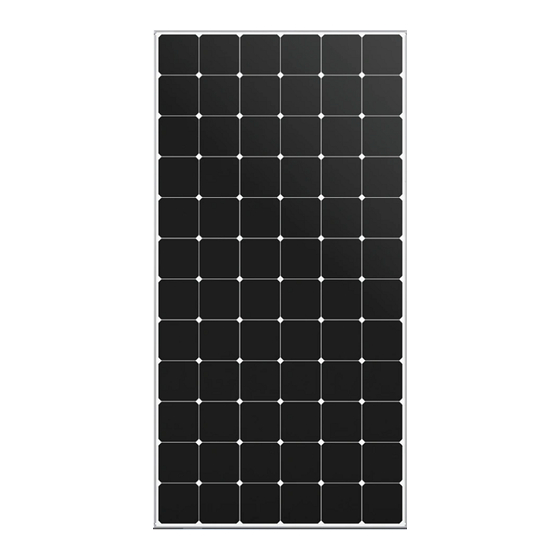
This document applies to Maxeon PV modules
This document includes references to MAX3 and MAX6 modules. These
modules do not have grounding restrictions and all are compatible with high‐
efficiency transformerless inverters.
Contents of this manual are subject to change without notice.
For the latest version please refer to https://www.maxeon.com/us/InstallGuideUL
United States
listed in Table 1.
Maxeon Solar Technologies, Ltd.
www.maxeon.com
Document 544753 Rev.A
Advertisement
Table of Contents

Summary of Contents for Maxeon MAX3
- Page 1 Safety and Installation Instructions United States This document applies to Maxeon PV modules listed in Table 1. This document includes references to MAX3 and MAX6 modules. These modules do not have grounding restrictions and all are compatible with high‐ efficiency transformerless inverters. Contents of this manual are subject to change without notice. For the latest version please refer to https://www.maxeon.com/us/InstallGuideUL ...
-
Page 2: Safety And Installation Instructions
Maxeon installation instructions and Switch off the inverter before disconnecting, reinstalling or making any action operations and maintenance instructions of any type, as may be amended and with the modules. updated from time to time at Maxeon’s sole discretion, and all national, state, For connectors, which are accessible to untrained people, it is imperative to and local laws, codes, ordinances, and regulations); (iii) repair or modification by use the locking connectors and safety clips, if applicable, in order to defend ... -
Page 3: Module Mounting
MAXEON SOLAR TECHNOLOGIES, LTD. Safety and Installation Instructions ‐ Document 544753 Rev.A irradiance per IEC 60904‐3 or irradiation of (air mass) AM 1.5 global (G) spectrum. In addition, to avoid corrosion due to the use of dissimilar metals Maxeon Each module contains three bypass diodes. The maximum series fuse rating is recommends stainless steel between copper and aluminum. 15A(X‐Series), for MAX3 and MAX6 modules it is 20A 4.2 System Grounding Under normal conditions, a photovoltaic module may experience conditions that Review Table 2 below for the proper grounding techniques for the installation of produce more current and/or voltage than reported at Standard Test Conditions. your particular Maxeon modules. Accordingly, the values of ISC and VOC marked on UL Listed modules should always be multiplied by a factor of 1.25 when determining component voltage 4.3 Series Connection ratings, conductor capacities, fuse sizes and size of controls connected to the The modules may be wired in series to produce the desired voltage output. Do module output. Refer to Section 690‐8 of the NEC for an additional 1.25 Safety not exceed the maximum system voltage shown in module datasheets and factor which may be applicable. product label. Table 1: Electrical Characteristics 4.4 Parallel Connection Voltage Open Short The modules may be combined in parallel to produce the desired current output. Rated Current Current Voltage Power at Rated Circuit ... -
Page 4: Mounting Configurations
Clamps: Mount the module with the opposite clamps on the longer and/or shorter sides of the module. The clips Force must not deform allowed location should be according top frame flange or Excluded Operating Environments glass may break Force to Appendix. Installers should ensure Certain operating environments are not recommended for Maxeon modules, and has to the clamps are of sufficient strength are excluded from the Maxeon Limited Warranty. No Maxeon module should be to allow for the maximum design mounted at a site where it may be subject to direct contact with salt water, or applied pressure of the module. Clamps are other aggressive environment. in line not provided by Maxeon. Clamps must with Modules should not be installed near flammable liquids, gases, or locations with frame apply force collinear with the ‘wall’ of hazardous materials; or moving vehicles of any type. wall the module frame and not only to the ... -
Page 5: Maintenance And Cleaning
Periodic cleaning of module glass has resulted in improved performance levels, especially in regions with low levels of annual precipitation; therefore Maxeon recommends periodic cleaning of the modules. To clean a module, wash its glass surface with potable, non‐heated water. Normal water pressure is adequate when cleaning the AR glass. Some fingerprints, stains, or accumulations of dirt on the glass may be removed with ® over‐the‐counter glass cleaners (such as Windex or equivalent), or a 3% with soap‐and‐water solution. For smaller systems, wet the module glass with the solution, let it stand for five minutes, and then wet them again and use a soft sponge or seamless cloth to wipe the glass surface in a circular motion. For large systems, wet the modules with the cleaning solution, let them stand for five minutes, and then rinse them with high‐pressure water or a soft squeegee. Do not use harsh industrial‐strength cleaning materials such as scouring powder, steel wool, scrapers, blades, or other sharp instruments to clean the module glass. Use of such materials will void the product warranty Recommended Cable Managemen Maxeon Product Line: Portrait Stringing Leapfrog Stringing (Portrait) Landscape Stringing © 2022 Maxeon Solar Technologies, Ltd. All rights reserved. Specifications included in these instructions are subject to change without notice. Page | 5... - Page 6 5 In the cases where hybrid moun ng is necessary (combina on of long and short side moun ng), the lowest par es, unless there is a formal authoriza on by Maxeon. design load values should be considered as allowable design load.
- Page 7 5 In the cases where hybrid moun ng is necessary (combina on of long and short side moun ng), the lowest par es, unless there is a formal authoriza on by Maxeon. design load values should be considered as allowable design load.


Need help?
Do you have a question about the MAX3 and is the answer not in the manual?
Questions and answers