
Related Manuals for Cobra 2010 GTL WX


Summary of Contents for Cobra 2010 GTL WX
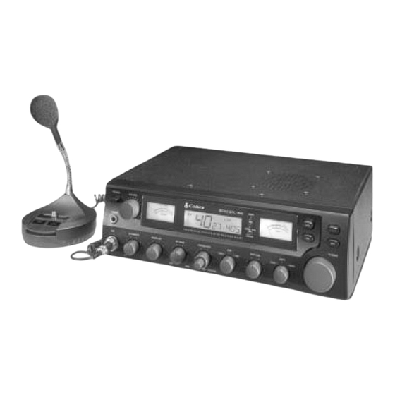
- Page 1 OPERATING INSTRUCTIONS FOR YOUR 40 CHANNEL SOLID STATE CITIZENS BAND SSB/AM TWO-WAY RADIO BASE STATION With Seven Weather Channels and NOAA Emergency Alert Tone Model 2010 GTL WX...
-
Page 2: Table Of Contents
How To Use Your Cobra SOLID STATE CITIZENS BAND SSB/AM 2-WAY RADIO BASE STATION Model 2010 GTL WX Contents The CB Story ... 1 Section I: Introduction ... 2 Section II: Specifications ... 3, 4 Section III: Installation ... 5 Section IV: Operation ... -
Page 3: The Cb Story
The CB Story The Citizens Band lies between the shortwave broadcast and 10-meter Amateur radio bands, and was established by law in 1949. The Class D two-way communications service was opened in 1959. (CB also includes a Class A citizens band and Class C remote control frequencies.) FCC regulations permit only “transmissions”... -
Page 4: Section I Introduction
Section I Introduction FREQUENCY RANGE The COBRA 2010 GTL WX transceiver represents one of the most advanced AM base station radios used as a Class D station in the Citizens Radio Service. This unit features advanced Phase Lock Loop (PLL) circuitry providing complete coverage of all 40 channels as shown below. -
Page 5: Section Ii Specifications
Section II Specifications GENERAL Channels Frequency Range Frequency Control Frequency Tolerance Operating Temperature Range Microphone Power Source Power Consumption Current Drain (13.8V DC) Size Weight Antenna Conductor Semiconductors Meter 1 Meter 2 TRANSMITTER Power Output Modulation Intermodulation Distortion SSB Carrier Suppression Unwanted Sideband Frequency Response Output Impedance... -
Page 6: Section Ii: Specifications
Section II Specifications (Cont.) RECEIVER Sensitivity Selectivity Image Rejection IF Frequency Adjacent-Channel Rejection AM and SSB RF Gain Control Automatic Gain Control (AGC) Squelch Noise Blanker Voice Lock Range Audio Output Power Frequency Response Built-in Speaker External Speaker (Not Supplied) CLOCK/COUNTER Clock Counter... -
Page 7: Section Iii Installation
MOBILE OPERATION/EMERGENCY POWER OPERATION It is possible to operate the Cobra 2010 GTL WX from an external 13.8V DC power supply for emergency conditions or from an automobile battery for mobile operation. We recommend using a genuine Cobra DC power cord (not supplied). The DC power cord can be purchased through your local dealer, or direct from Cobra. -
Page 8: Section Iv Operation
CONTROLS AND INDICATORS There are eighteen controls, 2 meters, 1 LCD and 1 jack on the front panel of your 2010 GTL WX. A. CONTROL FUNCTIONS 1. POWER SWITCH. Press in to turn on radio. Press in, again, and release to turn off radio. - Page 9 Section IV Operation (Continued) SWR CAL CONTROL . In order for you to achieve maximum radiated power and the longest range, it is important that your antenna be in good condition, properly adjusted and matched to your transceiver. The Built-in SWR (standing wave ratio) meter lets you easily measure your antenna condition.
- Page 10 Section IV Operation (Continued) 15. PRESS-TO-TALK MICROPHONE. The receiver and transmitter are controlled by the press-to-talk switch on the microphone. Press the switch and the transmitter is activated; release switch to receive. When transmitting, hold the microphone two inches from the mouth and speak clearly in a normal "voice." The radio is supplied with a low-impedance 500-ohm dynamic desktop microphone.
-
Page 11: Indicator Functions
Section IV Operation (Continued) INDICATOR FUNCTIONS MODULATION METER. Indicates the percent modulation (AM only). The SWR/SWR CAL/MOD switch must be in the MOD position to read modulation. SWR METER. Measures the ratio of standing wave voltage of the antenna system. Used to properly adjust the length of the antenna, and to monitor the quality of the coaxial cable and all RF electrical connections. -
Page 12: Operating Procedure To Receive
Section IV Operation (Continued) OPERATING PROCEDURE TO RECEIVE 1. Place the WX/CB Switch in the CB position. 2. Turn the set ON by pressing the POWER Switch. 3. Adjust the VOLUME for a comfortable listening level. 4. Set the Channel selector switch to the desired channel. 5. -
Page 13: Frequency Counter/Lcd Digital Clock
2. HOUR SWITCH: Press this switch to get correct hour setting. 3. MINUTE SWITCH: Press this switch to get correct minutes setting. NOTE: the 2010 GTL WX uses a 24-hour clock display (no a.m. or p.m. indi- cated). Example: Display Reads... -
Page 14: Receiving Ssb Signals
Section IV Operation (Continued) RECEIVING SSB SIGNALS There are three types of signals presently used for communications in the Citizens Band: AM, USB, and LSB. When the MODE switch on your unit is placed in the AM position, only standard double-sideband, full carrier signals will be detected. An SSB signal may be recognized while in the AM mode by its characteristic “Donald Duck”... - Page 15 Section IV Operation (Continued) RECEIVING SSB SIGNALS continued Once the desired SSB mode has been selected, frequency adjustment may be necessary in order to make the incoming signal intelligible, the VOICE LOCK control allows the operator to vary frequency above and below the exact-center frequency of the received signal.
-
Page 16: Section V Maintenance And Adjustment
Section V Maintenance and Adjustment The COBRA 2010 GTL WX transceiver is specifically designed for the environment encountered in base station installations. The use of all solid state circuitry and its light weight result in high reliability. Should a failure occur, however, replace parts only with identical parts. -
Page 17: Section Vi Appendix
Section VI Appendix Citizens Band operators have largely adopted the “10-code” for standard questions and answers. Its use permits faster communications and better understanding in noisy areas. The following table lists some of the more common codes and their meanings. Code Meaning 10-1... -
Page 18: A Few Rules That Should Be Obeyed
Section VI Appendix (Continued) A FEW RULES THAT SHOULD BE OBEYED You are not allowed to carry on a conversation with another station for more than five minutes at a time without taking a one-minute break, to give others a chance to use the channel. -
Page 19: Use Channel 9 For Emergency Messages Only
Section VI Appendix (Continued) USE CHANNEL 9 FOR EMERGENCY MESSAGES ONLY FCC gives the following examples of permitted and prohibited types of communica- tions for use on Channel 9. These are guidelines and are not intended to be all- inclusive. Permitted ”A tornado sighted six miles north of town.”... -
Page 20: Alternate Microphones And Installation
The microphone should provide the functions shown in schematic below. 5 WIRE MIC CABLE Pin Number Fig. 1. Cobra 2010 GTL WX microphone schematic. If the microphone to be used is provided with pre-cut leads, they must be revised as follows. - Page 21 Section VI Appendix (Continued) Fig. 4. Microphone plug pin numbers viewed from rear of pin receptacle. Be sure that the housing and the knurled ring of Fig. 3 are pushed back onto the microphone cable before starting to solder. If the washer is not captive to the pin receptacle body, make sure that it is placed on the threaded portion of the pin receptacle body before soldering.
- Page 22 Section VI Appendix (Continued) Fig. 2. Microphone Cable Preparation To wire the microphone cable to the plug provided, proceed as follows. Fig. 3. Microphone plug wiring. Remove the retaining screw. Unscrew the housing from the pin receptacle body. Loosen the two cable clamp retainer screws. Feed the microphone cable through the housing, knurled ring and washer as shown Fig.
-
Page 23: If You Need Service
5. Ship prepaid and insured by way of a traceable carrier ( to avoid loss in transit) such as United Parcel Service (UPS), Roadway Parcel Service (RPS) or First Class Insured Mail to Cobra Factory Service, Cobra Electronics Corporation, 6500 W. Cortland St., Chicago, IL 60707. Cobra is not responsible for units not received if package has not been properly insured. -
Page 24: Limited Two Year Warranty
WARRANTY Limited Two Year Warranty COBRA ELECTRONICS CORPORATION warrants that its COBRA citizens band (CB) radio, and the component parts thereof, will be free of defects in workmanship and materials for period of two (2) year from the date of first consumer purchase. This warranty may be enforced by the first consumer purchaser, provided that the product is utilized within the U.S.A. -
Page 25: Cobra Cb Radio Accessories
8240 cable and PL-259 connector ATW-2000 DUAL BAND ANTENNA Truck mirror mount, 48" stainless steel whip, weather tunable DC POWER CORD for 2010 GTL WX 93 ATW INDOOR DUAL BAND (CB/WEATHER) BASE STATION ANTENNA with 15 ft. coaxial cable ATW-93 Illinois residents add 7% Cook County, IL residents additional .75% (7.75% total) - Page 26 FOLD HERE TO MAKE SELF MAILER PLACE STAMP HERE Cobra ® Cobra Electronics Corporation 6500 W. Cortland Street Chicago, IL 60707 PRINTED IN MALAYSIA ©COBRA ELECTRONICS CORP. 1996 480-114-P-001...
Need help?
Do you have a question about the 2010 GTL WX and is the answer not in the manual?
Questions and answers