Table of Contents
Advertisement
Quick Links
Radeberger Straße 21 – D-01900 Großröhrsdorf
E-Mail: info@dks-engineering.de
Tel.: +49 35952 4294-65
WEB: https://www.dks-engineering.com
USER MANUAL for
meter with U/I input
PD96
type:
firmware version: 5.18 or higher
Read the user's manual carefully before starting to use the unit.
Producer reserves the right to implement changes without prior notice.
V.2.04
25.03.2010
Advertisement
Table of Contents

Subscribe to Our Youtube Channel
Related Manuals for DKS PD96


Summary of Contents for DKS PD96
- Page 1 Radeberger Straße 21 – D-01900 Großröhrsdorf E-Mail: info@dks-engineering.de Tel.: +49 35952 4294-65 WEB: https://www.dks-engineering.com USER MANUAL for meter with U/I input PD96 type: firmware version: 5.18 or higher Read the user's manual carefully before starting to use the unit. Producer reserves the right to implement changes without prior notice.
-
Page 2: Table Of Contents
User manual for meter with U/I input PD96 Contents 1. Basic requirements and user safety 2. General characteristics 3. Technical Data 4. Device installation. 4.1. Unpacking 4.2. Assembly 4.3. Connection method 4.4. Maintenance Front panel description Principle of operation 6.1. Measurement mode 6.2. - Page 3 User manual for meter with U/I input PD96 10.2. Examples of calculations 11. The modbus protocol handling 11.1. List of registers 11.2. Transmission error description 11.3. Examples of query/answer frames 12. Default and user´s settings list...
-
Page 4: Basic Requirements And User Safety
User manual for meter with U/I input PD96 Explanation of symbols used in the manual: This symbol denotes especially important guidelines concerning the installation and operation of the device. Not complying with the guidelines denoted by this symbol may cause an accident, damage or equipment destruction. -
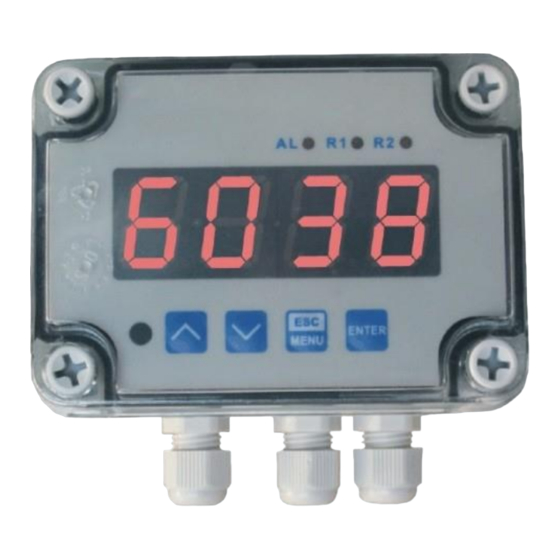
Page 5: General Characteristics
2 General characteristics The PD96 meter is equipped with one current input 0-20 / 4-20mA and one voltage input 0-5 / 1-5 / 0-10 / 2-10V. Current input has additionally overcurrent protection circuit, which protects standard resistor. -
Page 6: Technical Data
User manual for meter with U/I input PD96 3 Technical data Power supply voltage 230V AC ± 10%, 50 ÷ 60 Hz (depending on version) or 110V AC ± 5%, 50 ÷ 60 Hz or 24V DC ± 15%, (not separated) External fuse (required) T - type, max. - Page 7 User manual for meter with U/I input PD96 Protection level P 65 Housing type wall mounted Housing material ABS + fibreglass Housing dimensions without glands: 110 x 80 x 67 mm with glands: 110 x 105 x 67 mm Operating temperature 0°C to +50°C...
-
Page 8: Device Installation
User manual for meter with U/I input PD96 4. Device installation The unit has been designed and manufactured in a way assuring a high level of user safety and resistance to interference occurring in a typical industrial environment. In order to take full advantage of these characteristics installation of the unit must be conducted correctly and according to the local regulations. -
Page 9: Assembly
User manual for meter with U/I input PD96 4.2. Assembly - Disconnect the power supply prior to starting assembly. - Check the correctness of the performed connections prior to switching the unit on. To install device on the wall, a pinholes should be made. Figure 4.1 presents dimensions of the device and distances between holes. -
Page 10: Connection Method
User manual for meter with U/I input PD96 4.3. Connection method Caution - Installation should be conducted by qualified personnel . During installation all available safety requirements should be considered. The fitter is responsible for executing the installation according to this manual, local safety and EMC regulations. - Page 11 User manual for meter with U/I input PD96 Due to possible significant interference in industrial installations appropriate measures assuring correct operation of the unit must be applied. To avoid the unit of improper indications keep recommendations listed below. – Avoid common (parallel) leading of signal cables and transmission cables together with power supply cables and cables controlling induction loads (e.g.
- Page 12 User manual for meter with U/I input PD96 Figure 4.3. Terminals description (relay outputs) Figure 4.4. Terminals description (OC- type outputs) Figure 4.5. Connection of 2-wire current converters...
- Page 13 User manual for meter with U/I input PD96 Figure 4.6. Connection of 3-wire current converters Figure 4.7. Connection of voltage converters Figure 4.8. Connection of power supply and relays Contacts of relay outputs are not equipped with spark suppressors. While use the relay outputs for switching of inductive loads (coils, contactors, power relays, electromagnets, motors etc.) it is required to...
- Page 14 User manual for meter with U/I input PD96...
- Page 15 RS-485 interface separators must to be used certainly (Figure 4.14, 4.15). If RS-485 interfaces are isolated or not used then the separators are not necessary. Figure 4.12. Serial connection of active 2-wire sensor with PD96 unit and other current measurement device (e.g. PLC controller)
- Page 16 User manual for meter with U/I input PD96 Figure 4.13. Serial connection of passive 2-wire sensor with PD96 unit and other current measurement device (e.g. PLC controller). If device B (Figure 4.14 , 4.15) is equipped with galvanic separated input or if different potentials between A and B devices signal grounds are allowed (e.g.
- Page 17 User manual for meter with U/I input PD96 Let US min.=12V and Ug=5V then: If current loop is closed without the separator G, then sum of measurement input resistance (RB max.) of device B (Figure 4.15) and connections resistance (RW max.) should be not grater than result of given below formula: For example if US min.=12V then:...
-
Page 18: Maintenance
User manual for meter with U/I input PD96 4.4. Maintenance The unit does not have any internal replaceable or adjustable components available to the user. Pay attention to the ambient temperature in the room where the unit is operating. Excessively high temperatures cause faster ageing of the internal components and shorten thefault-free time of unit operation. -
Page 19: Principle Of Operation
User manual for meter with U/I input PD96 Symbols and functions of push-buttons: Symbol used in the manual: [ESC/MENU] Functions: • Enter to main menu ( press and hold by at least 2 sec.) • Exit the current level and Enter to previous menu (or measure mode) •... -
Page 20: Detection Of The Peak Values
6.2. Detection of the peak values The PD96 controller is equipped with peaks detection function. It can detect a peaks of the input signal and display their values. Presets connected with this function are placed in ”HOLd” menu (see description of ”HOLd” menu). The detection of the peak can be done if the measured signal raises and drops of value at least equal to parameter ”PEA”. -
Page 21: Control Of The Relay Outputs
User manual for meter with U/I input PD96 displayed and display time counter will be cleared (Figure 6.3). If no peaks are detected while time ”timE” elapses, device starts to show the current value of input signal again. If „HdiS”=”HOLD” then setting parameter "timE"=0.0 causes holding peak value until [ESC] button is pressed. - Page 22 User manual for meter with U/I input PD96 is contained in zone A (“modE” = ”in”) or zone B (“modE” = ”out”) and turned off if the signal is contained in the second one. Figure 6.4. One threshold control of the relay/LED outputs Figure 6.5.
-
Page 23: One Threshold Mode
User manual for meter with U/I input PD96 6.3.1. One threshold mode Figure 6.6 presents the principle of relay outputs operation for one threshold mode, and an example values of other parameters. Description: A, B, C, D points where measured signal exceeds border values (expected value ±... - Page 24 User manual for meter with U/I input PD96 “SEtP” sets a threshold of the relay, and parameter “HYSt” sets a Parameter hysteresis of the relay (Figure 6.6 a). The relay can change his state only when input value exceeds (over or under) border value and...
-
Page 25: Two Thresholds Mode
User manual for meter with U/I input PD96 6.3.2. Two thresholds mode Description: A, B, C, D, E points where measured signal exceeds border values (expected value ± allowed deviation) relays state changes moments: (for “t on” > 0, “toFF” > 0) time periods while input signal is in zone A or zone B Figure 6.7. -
Page 26: Device Programming
User manual for meter with U/I input PD96 Figure 6.7 presents the principle of relay outputs operation for two thresholds mode, and an example values of other parameters. In this mode parameter “SEt2” is accessible in common with “SEtP”, this parameter describes a second threshold of the relay output. -
Page 27: Parameters Edition
User manual for meter with U/I input PD96 to enter correct one before proceeding to menu options . Entering of the passwords is similarto the edition of numeric parameters (see: PARAMETERS EDITION ), however presently editing digit is showed only on the display, other digits are replaced by “-”... -
Page 28: Numeric Parameters (Digit Change Mode)
User manual for meter with U/I input PD96 7.2.1. Numeric parameters (digit change mode) Numerical parameters are displayed as decimal numbers. The mode of its new value entering depends on chosen edit method ( see parameter „Edit”). In mode “by digit” („Edit”=”dig”) pressing one of the keys [^] or [v] causes change of current position (flashing digit) or the sign (+/-). -
Page 29: Menu Description
User manual for meter with U/I input PD96 Functions of buttons when editing numeric and switching parameters: While editing numeric parameter: • change of current (flashing) digit • slide change of value (acceleration, deceleration, direction change) While editing switch parameter - selection of switch parameter. - Page 30 User manual for meter with U/I input PD96 “SEtP” first threshold of the relay (range -999 ÷ 9999). Negative values can be input by selecting a “-” sign on first digit (to change value use [^] and [v] buttons). Threshold is the medium value of relay hysteresis.
- Page 31 User manual for meter with U/I input PD96 “out” two threshold mode, relay is turned ON when the input value is bigger than “bigger threshold + HYSt” and lower than “lower threshold – HYSt”, and turned on when the input signal is contained in the secondzone.
-
Page 32: Inpt" Menu
User manual for meter with U/I input PD96 If parameter “modE” is set to “on” , “oFF”, “in” or “Out” the “critical situation” means that allowable measurement range is exceeded. If parameter “modE” is set to “modb”, the “critical situation” means communication delay (when no data is received) longer than “mbtO”... - Page 33 User manual for meter with U/I input PD96 The process of displayed result calculation is described in details in display values calculation paragraph. ”FiLt” this parameter sets filtration rate. It can be set to values from 0 (no filtration ) to 5 (strongest filtration – time window about 2 sec).
- Page 34 User manual for meter with U/I input PD96 “dELP” this option allows user to delete any of the points of the user defined characteristic. After selection current number of points of the user defined characteristic is displayed for about approx. 1.5 sec. After that device waits for selection of point being deleted (by [^], [v] buttons).
- Page 35 User manual for meter with U/I input PD96 Figure 7.1. Example of definition of permissible range of input signal – “Lo r” and “Hi r” parameters (“4-20” mode) The “Lo r” parameter is important if input is set to “4-20”, “1-5” or “2-10” mode only, and determines lower border of the permissible range.
-
Page 36: Bri" Parameter
User manual for meter with U/I input PD96 7.3.3. ”bri” parameter This parameter allows user to set bright of the LED display, bright can be set to conventional values from 1 to 8. 7.3.4. ”HOLd” menu This menu contains parameters connected with peak detection function. See also full description of the peak detection function in paragraph: detection of the peak values “modE”... -
Page 37: Secu" Menu
User manual for meter with U/I input PD96 7.3.5. ”SECu” menu This menu contains presets connected with availability of other parameters: ‘‘Scod’’ user password (4-digits number). If this parameter is set at value “0000”, userpassword is turned off. If the user do not remember his password, the access to the menu is possible by the “one-use password”. -
Page 38: Edit" Parameter
User manual for meter with U/I input PD96 The access to registers no 04h i 05h cant be denied by ”mbAc” parameter (see: list of registers). ”mbtO” this parameter defines maximal time (sec) between following frames received by the device. If the delay will be greater than the value of ”mbtO”... -
Page 39: Serv" Menu
User manual for meter with U/I input PD96 ”SErv” menu 7.3.9. This menu contains the parameters for authorized service only. To enter this menu proper service password must be entered. Improper settings can causes of damage of the device. 7.4. Menu structure... - Page 40 User manual for meter with U/I input PD96...
-
Page 41: The Alarm Led
User manual for meter with U/I input PD96 8. The alarm LED The ALARM LED (AL) is turned on when input signal is out of the permissible input range. See parameters: “tyPE”, “Lo r” and “Hi r” in paragraph „InPt” menu. -
Page 42: Additional Calculations (Used Conversion Characteristic)
User manual for meter with U/I input PD96 Additional calculations (used conversion characteristic) The manner of the additional computation of the displayed result depends on selected conversion characteristic. All presented charts are connected with the input range 4 – 20 mA. -
Page 43: Square Characteristic
User manual for meter with U/I input PD96 10.1.2. Square characteristic The normalized result is squared and further conversion is done as for linear characteristic. Conversion is made accordingly with the expression: where W means the displayed value. Figure 10.2. Normal (“Lo C” < “Hi C) and inverted (“Lo C” > “Hi C) characteristic 10.1.3. - Page 44 User manual for meter with U/I input PD96 Figure. 10.3 Normal („Lo C” < ”Hi C) and inverted („Lo C” > ”Hi C) characteristic 10.1.4. User defined characteristic User defined characteristic is defined as set of X-Y points. Number of the points is variable and may be set from 2 to 20 points which make linear segments (see graph and see Menu ”inPt”).
-
Page 45: User Defined Characteristic
User manual for meter with U/I input PD96 If the normalized result exceeds the user defined characteristic values, then specific utmost segment, defined by two next points, is used for calculations. If characteristic from figure below is used, and if In>1 then segment defined by points X(PL) = “90.0.”, X(PH) = “100.0.”... - Page 46 User manual for meter with U/I input PD96 Example 3: The linear characteristic Let the input mode = 4-20 mA, and parameters “Lo C” and “Hi C” equal to -300 and 1200 respectively. The calculations will be done for there different input currents from example 2.
- Page 47 User manual for meter with U/I input PD96 W @ 919 + (-300) = 619 b) Iin = 2,5 mA and In = -0,0938 , normalized result is negative , so the displayed value is equal to “Lo C” parameter: W @ “Lo C” = -300.
-
Page 48: The Modbus Protocol Handling
User manual for meter with U/I input PD96 b) Iin = 2,5 mA and In = -0,0938, because of the normalized In value is lower than 0, the segment defined by X1 and X2 will be selected. X1(PL) = 0, Y1(PL) = -50, X2(PH) = 10, Y2(PH) = -30 and Ip = 0. - Page 49 User manual for meter with U/I input PD96...
- Page 50 User manual for meter with U/I input PD96...
-
Page 51: Transmission Error Description
User manual for meter with U/I input PD96 after writing to register no 20h the device responds with an “old” address in the message. after writing to register no 22h the device responds with the new baud rate he value of the “mbAc” parameter is also connected to write to this register, so it is possible to block a writes, but impossible to unblock writes via RS-485 interface, The unblocking of the writes is possible from menu level only. -
Page 52: Examples Of Query/Answer Frames
CRC L,H CRC error check (Hi and Lo byte) 1. Read of the displayed value (measurement), PD96 device address = 01h: a) The answer (we assume that the measure result is not out of range): DATA H, L - displayed value = 255, no decimal point. - Page 53 User manual for meter with U/I input PD96 2. Read of device ID code The answer: Data – identification code (21 F0h) 3. Change of the device address from 1 to 2 (write to reg. 20h) Data H – 0 DATA L –...
-
Page 54: Default And User´s Settings List
User manual for meter with U/I input PD96 Device do not reply to BROADCAST-type messages. 5. Read of the registers 1, 2 and 3 in one message (example of reading a number of registries in one frame): COUNT L – the count of being read registers (max 16.) The answer: DATA H1, L1 - reg. - Page 55 User manual for meter with U/I input PD96...
- Page 56 User manual for meter with U/I input PD96...
- Page 57 User manual for meter with U/I input PD96 Radeberger Straße 21 – D-01900 Großröhrsdorf E-Mail: info@dks-engineering.de Tel.: +49 35952 4294-65 https://www.dks-engineering.com...
Need help?
Do you have a question about the PD96 and is the answer not in the manual?
Questions and answers