
Related Manuals for Friendess FSCUT4000

Summary of Contents for Friendess FSCUT4000
- Page 1 FSCUT4000 Laser Cutting Control System FSCUT4000 Laser Cutting System User Manual Shanghai Friendess Co., Ltd www.fscut.com Ver. 2.0...
- Page 2 Thank you for choosing our products! This manual gives a detailed introduction to the usage of FSCUT4000 laser cutting controller, including technical features and installation instructions etc. For CypCut laser cutting software operation, please refer to the CypCut user manual. For other matters you can contact us directly.
-
Page 3: Table Of Contents
FSCUT4000 Laser Cutting Control System Content Product Description ........................6 1.1 Brief Introduction ........................6 1.2 Connection Diagram ......................6 1.3 Technical Reference ....................... 7 1.4 Control Card Installation ....................... 8 Install steps ......................8 1.4.1 Troubleshoot......................9 1.4.2 BCL3724 Wiring Instruction .......................11 2.1 BCL3724 Description ......................11... - Page 4 FSCUT4000 Laser Cutting Control System 3.5 Return Origin Config ......................42 3.6 Laser Configuration ......................43 CO2 laser configuration ..................43 3.6.1 IPG laser configuration ..................44 3.6.2 Feibo/Rofin/SPI/GSI/JK laser configuration .............45 3.6.3 Configuration of other laser type ................46 3.6.4 3.7 BCS100 Configuration......................46 3.7.1 Use BCS100 as height control unit..............46...
- Page 5 FSCUT4000 Laser Cutting Control System FAQ..............................66 8.1 Cutting is Slow or Jamming ....................66 8.2 Corner Over Burned ......................66 8.3 Laser No Emission .......................66 Appendix ............................68 9.1 Fly Cut Operation Guide......................68 Function ........................68 9.1.1 Function description ....................68 9.1.2 9.2 Pitch Error Compensation....................69 Pitch error compensation description ..............69...
-
Page 6: Product Description
Brief Introduction FSCUT4000 is a high performance laser cutting system of close-loop control developed by Shanghai Friendess Company. It is widely used in metal and non-metal laser cutting application, has gained wide popularity among users at home and abroad. This manual served as installation and operation guide for FSCUT4000 system. -
Page 7: Technical Reference
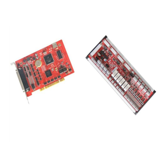
FSCUT4000 Laser Cutting Control System Computer Case BMC1214 PCI Card C62-2 BCL3724 I/O Board Technical Reference Analog output of 4 servo axis ports, -10V—+10V. Motor control Encoder feedback channel of 4 servo axis ports, 10MHz. signal Dedicated signal inputs of origin, positive/negative limit and servo alarm for each axis. -
Page 8: Control Card Installation
FSCUT4000 Laser Cutting Control System Control Card Installation 1.4.1 Install steps Please wear anti-static gloves to prevent possible electrostatic damage to the motion control card. Power off computer, insert the control card into PCI socket, and fix the control card tightly;... -
Page 9: Troubleshoot
FSCUT4000 Laser Cutting Control System 1.4.2 Troubleshoot (1) If "Find New Hardware" dialog box does not pop out after start up computer or control card does not shown in device manager, indicating that the control card is not in good connection with PCI socket. Please replace the PCI socket or change another computer, insert the control card tightly and reinstall software. - Page 10 FSCUT4000 Laser Cutting Control System indicates computer doesn't recognize the control card. Power off computer and change PCI socket, install the card firmly and repeat installation again. (5) If step (4) still fails, the control card might be damaged please contact our...
-
Page 11: Bcl3724 Wiring Instruction
FSCUT4000 Laser Cutting Control System 2. BCL3724 Wiring Instruction BCL3724 Description BCL3724 diagram shown as below: 62-pin socket... -
Page 12: Signal Type
FSCUT4000 Laser Cutting Control System You can either use guide rail or fixed installation to install BCL3724 board, product dimension 315mm*107mm. DB62M socket connected with JP1 interface of BMC1214 card by C62-2 cable. 4 sockets (DB15M) on top left are for servo control, from left to right is X, Y1, Y2 and W axis port. - Page 13 FSCUT4000 Laser Cutting Control System The typical wiring of photo-electric switch shown below, must use NPN 24V type switch. The typical wiring of contact switch shown below. The typical wiring of magnetic switch shown below, must use NPN 24V type switch.
-
Page 14: Relay Output
FSCUT4000 Laser Cutting Control System 2.2.2 Relay output There are 6 relay output on BCL3724 terminal board which are OUT1-OUT6. OUT1-OUT4 only support normally open, OUT5-OUT6 have both NO and NC options. The maximum load of relay: DC 30V, 8A; AC 250V, 8A. Recommend to use load under 2A, the inductive load or high power load will reduce the service time of relay switch. -
Page 15: Analog Output
FSCUT4000 Laser Cutting Control System 2.2.4 Analog output 3 analog output of 0-10V. Output range 0V~+10V Maximum output load 50mA Maximum capacitive load 350pF 100KΩ Input impedance Maximum bipolar error +/-50mV Resolution 10mV Conversion speed 400us 2.2.5 PWM output There is one PWM port on BCL3724 for laser average power modulation. There are 5V and 24V for options. - Page 16 FSCUT4000 Laser Cutting Control System below: The signal pin description of C15-1.5 cable listed below: 15-pin servo control interface Description Description DA (-10~10V analog) AGND (analog ground) 0S (zero speed clamp) 0V (power supply ground) A+ (encoder A phase positive)
-
Page 17: Servo Drive Control Signal
FSCUT4000 Laser Cutting Control System ALM signal jump wire to ACT_LOW, input is low-level active (input 0V active); Jump wire to ACT_HIGH, input is high-level active (input 24V active); Default is ACT_LOW. 2.3.3 Servo drive control signal The wiring diagram with Panasonic, Yaskawa, Sanyo and Schneider provided here. - Page 18 FSCUT4000 Laser Cutting Control System Panasonic servo wiring diagram FSCUT DB15 servo control MINAS-A 50P Shielding layer Signal Pin Signal 14 SPR/TRQR AGND COM+ SRV-ON ALM- ALM+ COM- Panasonic A5 reference setting Parameter Description Recommended value Pr0.01 Control mode Pr0.02 Real time auto tuning Pr0.04...
- Page 19 FSCUT4000 Laser Cutting Control System Yaskawa servo wiring diagram FSCUT DB15 servo control YaskawaΣ50P Shielding layer Signal Pin Signal V-REF AGND /PAO /PBO /PCO +24 VIN /S-ON ALM- ALM+ Yaskawa Sigma 5/7 reference setting Parameter Description Recommended value Pn000 0000...
- Page 20 FSCUT4000 Laser Cutting Control System Pn401 Torque command filter 0.30 MS time constant Pn50A Input signal 8100 Pn50B Input signal 6548...
- Page 21 FSCUT4000 Laser Cutting Control System Sanyo R series wiring diagram FSCUT DB15 servo control Sanyo R2 50P Shielding layer Signal Pin Signal V-REF AGND OUT-PWR CONT-COM CONT1 OUT-COM OUT8 Sanyo R2 reference setting Parameter Description Recommended value SY09 Control mode Gr0.00...
- Page 22 FSCUT4000 Laser Cutting Control System G rB.14 Release brake delay G rC.04 Differential pulse output Set by mechanism feature, the pulse equivalent should be among 1000-2000. For example, if the linear distance on machine load is 10mm per motor rotation, the pulse per revolution should...
- Page 23 FSCUT4000 Laser Cutting Control System Schneider Lexium 23D wiring diagram Lexium 23D FSCUT DB15 servo control Schneider Shielding layer Signal Pin Signal 42 V-REF AGND 44 GND 21 OA 22 /OA 25 OB 23 /OB 50 OC 24 /OC 11 COM+...
-
Page 24: Origin And Limit
FSCUT4000 Laser Cutting Control System P 2-32 ATMODE, automatic adjustment 2.3.4 Origin and limit X-: negative limit of X axis, dedicated input, low-level active; XO: origin of X axis, dedicated input, low-level active; X+: positive limit of X axis, dedicated input, low-level active;... -
Page 25: Analog Output
FSCUT4000 Laser Cutting Control System 2.3.7 Analog output 3 channels analog output of 0-10V, DA1, DA2 and DA3. Analog output can be assigned for laser peak power and gas valve control. 2.3.8 PWM output For fiber laser configuration in CypCut machine config, PWM will be activated automatically for laser average power regulation. -
Page 26: Wiring Diagram
FSCUT4000 Laser Cutting Control System Wiring Diagram DB62 socket 24V power +24V supply X- limit X origin X+ limit Y1- limit Y1 origin Y1+ limit PWM- Laser output modulation PWM+ Analog GND DA1- OUT1 Analog Laser Analog voltage output1 DA1+... -
Page 27: Laser Wiring Diagram
FSCUT4000 Laser Cutting Control System Laser Wiring Diagram 2.5.1 YAG laser Assign an output for laser emission and connect with laser. 2.5.2 CO2 laser Here take example of NT-3200SM CO2 laser. BCL3724_V2.0 Terminal Board OVNT CO2 laser 24P Analog output... -
Page 28: Ipg-Ylr
FSCUT4000 Laser Cutting Control System 2.5.3 IPG-YLR IPG_YLR Laser 25P Safety interlock1 Safety interlock2 Safety interlock2 Computer RS232 DB9 Safety interlock1 RS232 Rx RS232 Tx RS232 COM BCL3724_V2.0 I/O Board DIP switch PWM- Modulation+ output PWM+ Modulation- It's recommended to use serial communication (RS232) or network... -
Page 29: Ipg_ Yls Germany
FSCUT4000 Laser Cutting Control System 2.5.4 IPG_ YLS Germany IPG-Germany YLS Laser BCL3724_V2.0 I/O Board 64Pin XP1 thyristor output Laser ON OUT11 Laser ON OUT11 Laser Request OUT12 Laser Request OUT12 Program Start OUT13 OUT13 Program Start OUT14 Guide Laser On... -
Page 30: Ipg_ Yls American
FSCUT4000 Laser Cutting Control System 2.5.5 IPG_ YLS American IPG-American YLS Laser BCL3724_V2.0 I/O Board 64Pin XP1 Thyristor output Laser Request OUT11 OUT11 Laser Request Program Start OUT12 OUT12 Program Start Guide Laser On OUT13 Aiming OUT13 Common Anolog Control ON... -
Page 31: Spi-500W-R4
FSCUT4000 Laser Cutting Control System 2.5.6 SPI-500W-R4 SPI-500W R4 Laser Systems InterLock Interlock 1 Interlock 2 Interlock 2 Interlock 1 Computer RS232 DB9 RS232 Comms Port RS232 Rx RS232 Tx RS232 COM BCL3724_V2.0 I/O Board Mod Input TTL DIP Switch... -
Page 32: Feibo Mars
FSCUT4000 Laser Cutting Control System 2.5.7 FEIBO MARS Computer RS232 DB9 FEIBO MARS-500W Laser System D-SUB 9 RS232 Rx RS232 Tx RS232 COM BCL3724_V2.0 I/O Board D-SUB 15 DIP Switch PWM- Modulation+ output PWM+ Modulation- INTLK Note: Select 24V for PWM (DIP switch: PIN1 ON, PIN2 OFF). -
Page 33: Jk/Gsi-Fl
FSCUT4000 Laser Cutting Control System 2.5.8 JK/GSI-FL JK/GSI-500W-FL SK11 Computer RS232 DB9 Interlock Interlock Interlock Interlock RS232 Tx Interlock RS232 Rx Interlock RS232 COM Interlock Interlock Interlock Interlock BCL3724_V2.0 I/O Board SK101 PWM- Modulation+ output PWM+ Modulation- Note: 1. The interlock in SK11 interface 2. -
Page 34: Rofin
FSCUT4000 Laser Cutting Control System 2.5.9 Rofin Rofin Fiber Laser BCL3724_V2.0 I/O Board X710 Thyristor output OUT11 Mission ON Mains on OUT11 OUT12 Fault Reset Program Start OUT12 OUT13 Stand By Stand By OUT13 OUT14 Aiming Guide Laser On OUT14... -
Page 35: Raycus
FSCUT4000 Laser Cutting Control System 2.5.10 Raycus RayCus Fiber Laser InterLock Interlock1 Interlock1 Computer RS232 DB9 COMMAND RS232 RS232 Rx RS232 Tx RS232 COM BCL3724_V2.0 I/O Board INPUT MOD PWM- Modulation+ output PWM+ Modulation- Note: 1. Raycus's latest products use 24V PWM, the old versions use 5V PWM. For latest Raycus laser, key switch turns to REM under serial communication, while for old versions key switch turns to ON position under serial communication. -
Page 36: Max
FSCUT4000 Laser Cutting Control System 2.5.11 Max Max Fiber Laser InterLock Water chiller interlock Water chiller interlock BCL3724_V2.0 I/O Board Max Fiber Laser DIP Switch PWM- Modulation- output PWM+ Modulation+ OUT17 Aiming+ Assign thyristor output as OUT18 Emission on+ Emission on and Aiming... -
Page 37: Machine Config Tool
FSCUT4000 Laser Cutting Control System 3. Machine Config Tool Installation and Operation CypCut default installation contains machine config program. In Windows Start > All Programs > CypCut open machine config program 'CypCut laser cutting system' is software name which might be different of OEM version. -
Page 38: User Interface
FSCUT4000 Laser Cutting Control System User Interface The first page open machine config is machine config overview. Click tab in top and left bar will open each parameter setup page for different machine module. For example, above three are entrance for laser, height control and gas system setting page. -
Page 39: Mechanism Config
FSCUT4000 Laser Cutting Control System Mechanism Config Config mechanism structure, single drive Y axis or dual-drive Y axis, also config rotary axis. X axis range: the maximum travel range under software limit protection function, also the width of white frame in CypCut drawing board. - Page 40 FSCUT4000 Laser Cutting Control System and offset error data from interferometer. Squareness: this is to offset the error when X and Y mechanic is not orthogonal. X/Y check: used for motor runaway risk checking. Motor runaway check: to check if the motor rotation direction same with encoder feedback.
- Page 41 FSCUT4000 Laser Cutting Control System 30rpm 100ms 100ms 50ms -30rpm Close-loop jog: check the option and jog X axis, observe the motor rotation and encoder feedback polarity. Open-loop jog: check the option controller only send analog output, doesn't compare with feedback. Dual-drive axis doesn't recommend this function.
-
Page 42: Return Origin Config
X and Y are both in negative direction, system runs in first quadrant coordinate. Origin signal: FSCUT4000 must use origin switch, cannot take limit as origin. ORG measure: measure the installation distance between limit and origin switch. Z-phase signal: whether or not capture Z-phase signal results different return... -
Page 43: Laser Configuration
FSCUT4000 Laser Cutting Control System origin process. The return origin process of each mode will display in picture. Dual- drive gantry synchronize function only available when capture Z-phase signal return origin. Low speed: fine positioning speed, recommend to set 10mm/s. -
Page 44: Ipg Laser Configuration
FSCUT4000 Laser Cutting Control System Laser form: laser form can be set as continuous wave, gate pulse and high power pulse by mode 1 and mode 2 output. DA port: there are three DA analog output, select one of them for laser power control. -
Page 45: Feibo/Rofin/Spi/Gsi/Jk Laser Configuration
FSCUT4000 Laser Cutting Control System button. If use remote start button, you need to setup the output port for the button. (Remote start up button is not recommended, for it's easy to cause laser malfunction). IPG remote control: When use IPG remote control, CypCut will monitor laser status in real time, then communicate and control laser emission, guide beam and peak current etc. -
Page 46: Configuration Of Other Laser Type
FSCUT4000 Laser Cutting Control System 3.6.4 Configuration of other laser type Shutter enable: output to open laser shutter. BCS100 Configuration 3.7.1 Use BCS100 as height control unit Use BCS100 as height control unit, set IP address in machine config same in BCS100. -
Page 47: Use External Device As Height Control Unit
FSCUT4000 Laser Cutting Control System 3.7.2 Use external device as height control unit CypCut supports I/O control mode for height controller of other brand. User can assign output with basic functions of lift, hold, up and down etc. Start follow: output to start follow. -
Page 48: Gas System
FSCUT4000 Laser Cutting Control System Gas System Valve (H/L): master valve of high pressure or low pressure gas channel. Air: set output for air switch. Oxygen: set output for oxygen switch. Nitrogen: set output for nitrogen switch. Gas alarm: to set alarm check for each gas channel or master valve. -
Page 49: Warning Message
FSCUT4000 Laser Cutting Control System 3.9.1 Warning message Display the warning message of yellow color when machine is running. You can edit the warning message. 3.9.2 Emergency stop button When this signal port active will trigger emergency stop alarm. 3.9.3 Safety mode Safety mode used for machine maintenance mode, under which machine speed and laser power will all be restricted to preset safety range. -
Page 50: Common Input
FSCUT4000 Laser Cutting Control System 3.10 Common input Click button and select controlled function and active level of input signal. -
Page 51: Common Output
FSCUT4000 Laser Cutting Control System 3.11 Common output 3.11.1 Output configuration Aiming: output to control guide laser. Lasering: system will send an output signal for indicator lamp when laser in emission. Working: system will send an output signal for indicator lamp when laser in production. -
Page 52: Custom Output
FSCUT4000 Laser Cutting Control System length counting and turn on/off lubrication when reach preset time/mileage interval. 3.11.3 Custom output Assigned I/O will display software button under CypCut CNC tab. Custom I/O can select contact or self-lock control method. 3.11.4 Regional output Regional output used for automatic dust extracting. -
Page 53: Bcp5045 Panel
FSCUT4000 Laser Cutting Control System 3.13 BCP5045 Panel Enable BCP5045 panel in this page. In stand-alone environment, CypCut will connect to BCO5405 Mac address. In LAN environment, input ID of BCP5045. There are 12 custom buttons which can be assigned for machine function like PLC control or... -
Page 54: Electrical System Adjustment
FSCUT4000 Laser Cutting Control System 4. Electrical System Adjustment Power Supply Checking Connect BCL3724 I/O terminal board and BMC1214 control card by C62-pin cable, give 24V power supply to BCL3724 board. Make sure power supply in right wiring and no short circuit before power up. - Page 55 FSCUT4000 Laser Cutting Control System Second, check motor direction and feedback pulse direction from encoder. Click open ‘motor axis checking’ page. 1. Click to start motor runaway test. 2. Click option, then jog motor in both directions, if motor motion direction not same with command direction in CypCut, click reverse it.
-
Page 56: Hardware Signal Checking
FSCUT4000 Laser Cutting Control System Hardware Signal Checking Startup computer and open CypCut software. Open File tab > Diagnosis > IO Monitor. Check each signal one by one: positive limit/negative limit/origin switch of each motor axis, DA signal, PWM signal, servo enable signal and all other input and output... -
Page 57: Basic Motion Test
FSCUT4000 Laser Cutting Control System Basic Motion Test First, set conservative PID value in servo driver. And set conservative value of motion control parameter in CypCut. In CypCut 'Layer' > 'Global Parameter' shown as below: Test single motor axis make sure pulse equivalent set right. - Page 58 FSCUT4000 Laser Cutting Control System...
-
Page 59: Adjustment Steps
FSCUT4000 Laser Cutting Control System 5. Adjustment Steps 1.Select velocity control mode; 2.Set input gain of speed command; 3.Set encoder differential pulse output per motor revolution; Servo drive 4.Velocity loop gain 75hz,time setting integral 9ms and set velocity loop rigidity level, 5.Confirm select external enable... -
Page 60: Common Problems In Close-Loop Control
FSCUT4000 Laser Cutting Control System 6. Common Problems in Close-Loop control Motor Runaway Error Error source: system doesn't receive feedback pulse or receive abnormal pulses from encoder. Checking points: (1) Check the wiring, make sure servo enable signal, speed command signal and encoder signal are wired with correct signal pin;... - Page 61 FSCUT4000 Laser Cutting Control System (1) Open CypCut machine config, and execute make sure the checking passed; (2) If this error came after increasing acceleration in CypCut, might be caused by motor torque being restricted. Driver settings restrict motor torque or motor itself is of low torque type;...
-
Page 62: Optimize Machine Motion Performance
FSCUT4000 Laser Cutting Control System 7. Optimize Machine Motion Performance Calculate Inertia Ratio and Preview Machine Performance Features The inertia ratio is a crucial indicator of machine performance features. You can calculate inertia ratio of each motion axis of machine by ServoTools. Download link is http://downloads.fscut.com/. -
Page 63: Motion Control Parameter Adjustment
Motion Control Parameter Adjustment 7.2.1 Motion control parameter description Speed, acceleration, low-pass filter frequency, corner and curve precision in FSCUT4000 system are available for users to adjust, other parameters related with motion control are optimized automatically. Parameter description listed below: Name... -
Page 64: Adjust Travel Acceleration
FSCUT4000 Laser Cutting Control System distance to reach the pre-set speed. Monitor the torque curve in servo tool when jog control the axis, increase the cutting acceleration if peak torque is under 80% of rated value, lower the cutting acceleration if peak torque is below 80% of rated value. -
Page 65: Curve Precision And Corner Precision
FSCUT4000 Laser Cutting Control System marking contour precision. The standard of contour precision should be no waving at corner position in cutting star, rectangular or polygon etc. You can setup by experiential value in below table. Setup the cutting acceleration then adjust LPF 2 levels around. -
Page 66: Faq
FSCUT4000 Laser Cutting Control System 8. FAQ Cutting is Slow or Jamming In CypCut, open 'node mode' to view the drawing, if graphic contour made of a lot nodes, please optimize and smooth the graphic before cutting. Check the cutting parameter setting see if there is improper setting of time delay, or mixed time unit set 200ms to 200s for example. - Page 67 FSCUT4000 Laser Cutting Control System different with Germany version. If use serial or Ethernet communication, check in PC if select correct communication port. If use analog signal to control laser peak power, check if select right DA port.
-
Page 68: Appendix
FSCUT4000 Laser Cutting Control System 9. Appendix Fly Cut Operation Guide 9.1.1 Function There are new functions for CypCut later than V6.3.495: ‘fly cut’ also named ‘scan line cut’ in CypCut. This function applied in thin sheet cutting, used to cut arrayed parts of standard shape in high speed to improve production efficiency. -
Page 69: Pitch Error Compensation
Use 'Z phase' signal to improve return origin precision. FSCUT4000 system provides encoder feedback channel for each motor axis to ensure control precision. -
Page 70: Mechanic Error Measure
FSCUT4000 Laser Cutting Control System error. Precise pulse equivalent can be measured by interferometer. 9.2.4 Mechanic error measure In CypCut > CNC > Path function is to setup and create motion path for interferometer to capture and record measurement data. Machine runs and pauses in preset distance and time interval, meanwhile interferometer measures and records the actual position at each pausing point. -
Page 71: Import Measurement Data To Cypcut
FSCUT4000 Laser Cutting Control System Make sure the zero point of interferometer and machine origin in same position. Check in CypCut machine config, pitch compensation function should be disabled while still in measuring process. 9.2.5 Import measurement data to CypCut The measurement data file can be imported in CypCut. -
Page 72: The Operation Steps Of Pitch Error Compensation
FSCUT4000 Laser Cutting Control System Click to import measurement file of X axis, click to import measurement file of Y axis. Imported file will be shown in data table and graph. If the coordinate polarity in data table is different with return origin direction, then compensation invalid. -
Page 73: Faq
FSCUT4000 Laser Cutting Control System 9.2.7 FAQ 1. Pitch error doesn't change after compensation You need to execute return origin after import compensation file to let compensation data take effect. If the pulse equivalent is too small, for example, less than 200 pulses per 1mm, the compensation file doesn't work.
Need help?
Do you have a question about the FSCUT4000 and is the answer not in the manual?
Questions and answers