Table of Contents
Advertisement
Quick Links
Advertisement
Table of Contents

Related Manuals for Digital Equipment EtherWORKS Switch 6T/2TX


Summary of Contents for Digital Equipment EtherWORKS Switch 6T/2TX
- Page 1 EtherWORKS Switch 6T/2TX Installation Part Number: EK–DEL6X–IN. A01 This document describes how to install and operate the EtherWORKS Switch 6T/2TX. Revision/Update Information: This is a new manual. Digital Equipment Corporation Maynard, Massachusetts...
- Page 2 August 1996 Digital Equipment Corporation makes no representations that the use of its products in the manner described in this publication will not infringe on existing or future patent rights, nor do the descriptions contained in this publication imply the granting of licenses to make, use, or sell equipment or software in accordance with the description.
- Page 3 Operation of this equipment in a residential area may cause interference in which case the user at his own expense will be required to take whatever measures may be required to correct the interference. VCCI Class I Compliance ( V C C I ) This product complies with CISPR 22 Class A, UL, and is eligible to bear the CE Mark label.
-
Page 4: Table Of Contents
About This Manual ............................ix Conventions ..............................ix Package Contents ............................x Quick Installation............................xi 1 Introduction Overview of Switching Technology ......................1–1 EtherWORKS Switch 6T/2TX ........................1–2 Features..............................1–2 2 Hardware Description Overview ..............................2–1 Indicator Panel ............................2–1 Configure Button..........................2–2 LEDs..............................2–3 CPU LED (Power).......................... - Page 5 3 Hardware Installation Overview..............................3–1 Preinstallation Requirements ........................3–1 Hardware Installation ..........................3–2 Stacking the DEL6X Without a Rack ....................3–2 Mounting the DEL6X in a Rack ......................3–3 Connecting the DEL6X System......................... 3–3 Connecting to a PC, Server, or Workstation..................3–3 Connecting to Another Network Interconnection Device ..............
- Page 6 Other Digital Network Adapter Products ....................B–6 DE45X–AR Remote Boot ROM......................B–6 DE20M–AR Remote Boot ROM ....................... B–6 EtherWORKS Switch 2TTX (DEL2X) ....................B–6 EtherWORKS Hub 8TX (DELXR) Repeater ..................B–7 Fast EtherWORKS PCI 10/100 Adapter .................... B–7 EtherWORKS Turbo PCI 10 Adapter ....................B–7 EtherWORKS 3 Turbo Adapter ......................
-
Page 7: Preface
Preface About This Manual This guide is designed for the experienced network installer. It describes how to install and operate Digital’s EtherWORKS Switch 6T/2TX (DEL6X) switch (also referred to as the DEL6X or switch). Conventions The following conventions are used in this manual:... -
Page 8: Package Contents
Package Contents The EtherWORKS Switch 6T/2TX package contains the items in the following list and shown in the following figure: ™ • The EtherWORKS Switch 6T/2TX š • An ac power cord › • This installation guide œ • Four rubber feet... -
Page 9: Quick Installation
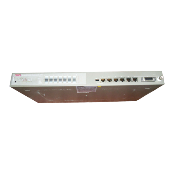
Quick Installation The EtherWORKS Switch 6T/2TX contains five 8 ² pin MJ 10 Mb/s Ethernet ports, one multimedia 10 Mb/s port, and two 8 ² pin MJ 100 Mb/s ports for Fast Ethernet connection. Each 8 ² pin MJ port supports full ² and half ² duplex operation. The smart design built into the front display panel and configuration options provides a friendly interface that simplifies installation and network troubleshooting. -
Page 10: Introduction
Introduction Overview of Switching Technology The Ethernet switch allows simultaneous transmission of multiple packets using an internal high–speed data channel. This means that it can partition a network more efficiently than bridges or routers in most environments. Therefore, the Ethernet switch is recognized as one of the most important building blocks for today’s networking technology. -
Page 11: Etherworks Switch 6T/2Tx
Introduction EtherWORKS Switch 6T/2TX The DEL6X can boost bandwidth. It provides five 10 Mb/s 8–pin MJ station ports and one 10 Mb/s TP/AUI/BNC combination (combo) port to connect to either a subnetwork, or directly to a PC, server, or key workstation, and two 8–pin 100 Mb/s Fast Ethernet ports for connection to a backbone or server. - Page 12 Introduction • Uses “on the fly” cut through switching technique to transport packets – • Minimum latency of packet transmission (leading edge to leading edge) of less than 20 microseconds when using cut –through switching • Supports transparent bridging function •...
-
Page 13: Hardware Description
Hardware Description Overview This chapter describes the hardware features of the EtherWORKS Switch 6T/2TX. For easier management of the switch, familiarize yourself with the front panel display LEDs, ports, and daisy-chain switches shown in the following illustrations and described in the following sections. -
Page 14: Configure Button
Hardware Description Configure Button ™ button, located on the left of the front panel ( in the following figure), is Configure used to select the following configuration functions: • Port status (displays status of ports during normal operation) • System performance (displays relative bandwidth utilization rate, forwarding ratio, or filtering ratio for each port) •... -
Page 15: Leds
Hardware Description LEDs The LEDs shown in the following figure indicate: š • The unit is receiving power and the CPU is running › • The current display mode œ • The statistical display for system performance • The demonstration, diagnostics, and full ² and half ² duplex display modes Configure LJ-5114.AI4 CPU LED (Power) -
Page 16: Collision Ratio (Collision%)
Hardware Description Collision% Transmit Receive Full Duplex Select/Link 10Base-T 100Base-TX LJ-5343.AI4 Collision Ratio (Collision%) Collisions occur when two or more devices connected to a DEL6X attempt to transmit data simultaneously on the network. When a collision occurs, the devices pause, then retransmit after a pseudo ²... -
Page 17: Receive Status
Hardware Description Receive Status The following table describes the Receive status LEDs when incoming traffic enters the port: LED Activity Condition Indication Blinking light Port is receiving packets; frequency of blinking is proportional to the traffic passing through the port No light No packets are being received on this port Select/Link Status... -
Page 18: Port Utilization Rate (Util%)
Hardware Description Port Utilization Rate (Util%) These LEDs show the percentage of valid data transmitted over the complete network bandwidth (updated every 0.5 seconds). There are eight LEDs representing the percentage of network utilization. The corresponding LEDs light to show that the utilization of LAN bandwidth has reached this percentage (see the following table). -
Page 19: Demonstration Display Mode (Demo)
Hardware Description Demonstration Display Mode (Demo) When this function is enabled (see the following table), the system cycles through all the DEL6X LEDs to verify that the LEDs are functioning. The LEDs will continue to light until the Demo function is disabled. LED Activity Condition Indication... -
Page 20: Port Diagnostic Test
Hardware Description Port Diagnostic Test The port diagnostic test checks all ports. If a problem is detected, the LEDs in the corresponding column (indicating the malfunctioning port) and row (indicating the failed component) will light as shown in the following table: LED (Row) Color Diagnostic Test Status... -
Page 21: 8-Pin Mj Ports
Hardware Description 8-Pin MJ Ports There are six 8–pin MJ 10 Mb/s Ethernet ports available on the front panel (shown in the ™ š following figure) and one daisy–chain switch . Five of these ports are dedicated ports › œ ... -
Page 22: Power Socket
Hardware Description ______________________________ Note ____________________________ If the AUI port is set to full–duplex mode, be sure your transceiver also supports full–duplex communications. _______________________________________________________________ BNC Port (10Base2) The DEL6X has a built–in BNC transceiver for connections using ThinWire coaxial cable. The BNC port can link up to 30 switches on one coaxial cable segment. The ThinWire coaxial cable that links the BNC ports may be extended up to 185 meters and have computers or other Ethernet devices attached to it. -
Page 23: Overview
Hardware Installation Overview This chapter provides information on the EtherWORKS Switch 6T/2TX preinstallation requirements, how to establish network connections, and how to configure the system. The DEL6X can be installed on any level surface (for example, a table or shelf), or mounted in a standard equipment rack. -
Page 24: Stacking The Del6X Without A Rack
Hardware Installation Hardware Installation The DEL6X is suitable for desktop or rack ² mount installation. It can be stacked with other switches using a mounting rack, or stacked directly on top of one another. The following sections describe these methods. Stacking the DEL6X Without a Rack To stack the DEL6X on top of another switch (shown in the next figure), use the following procedure:... -
Page 25: Mounting The Del6X In A Rack
Hardware Installation Mounting the DEL6X in a Rack To mount the DEL6X in a rack (shown in the next figure), use the following procedure: 1. Confirm that the rack you are using is an EIA standard size 19 ² inch rack. 2. -
Page 26: Connecting To Another Network Interconnection Device
Hardware Installation To connect the DEL6X to a PC, server, or workstation, use the following procedure: 1. Prepare the systems you wish to network. Make sure they have properly installed 10Base ² T or 100Base ² TX network interface cards (NICs). 2. - Page 27 Hardware Installation __________________________ Note _____________________________ To achieve the best performance when cascading switches, isolate your heaviest traffic within the internal pathways provided by the DEL6X (that is, avoid heavy loading on the interswitch links). ____________________________________________________________ To connect the DEL6X to another network interconnection device, use the following procedure: 1.
-
Page 28: Connecting To A Trunk Line
Hardware Installation Connecting to a Trunk Line The DEL6X can connect to an Ethernet trunk line using an AUI or BNC connection, if necessary. The DEL6X provides one combo port (Port 6) that automatically detects the current media type. To connect the DEL6X to a trunk line, use the following procedures: 1. -
Page 29: Verifying System Operation
Hardware Installation Verifying System Operation Verify that all attached devices have a valid connection The DEL6X monitors link status for each port. If any device is properly connected to the DEL6X and transmitting a link beat signal, the Link LED lights for the corresponding port. If the Link LED fails to light when you connect a device to the DEL6X, check the following items: •... -
Page 30: Setup And Configuration
Setup and Configuration Overview This chapter provides information on the EtherWORKS Switch 6T/2TX system setup that includes powerup diagnostics, and using the Configure button to perform diagnostic tests and to set display modes. Diagnostic Tests Upon powerup, the DEL6X performs an internal self–diagnostic test of major switch components. -
Page 31: Setting The Display Mode
Setup and Configuration Setting the Display Mode This section describes the information available for each display mode and the corresponding LEDs. The display functions are listed in the sequence selected by the Configure button. For a more detailed description of these LEDs, refer to Chapter 2. A long press on the button is used to initiate basic configuration. -
Page 32: Diagnostic Function
Setup and Configuration Diagnostic Function Active LED: Diag (ON) Enabling the Diagnostic function will activate diagnostic tests similar to the one performed upon powerup. After successfully completing diagnostics, the system returns to normal operation. For diagnostic test details, refer to the Diagnostic Tests section in this chapter Full–/Half–Duplex Mode Selection Active LED: Full/Half (ON) This function is used to set the communication mode for selected ports to full–duplex or... -
Page 33: Applications
Applications Overview This chapter describes some of the common applications for the EtherWORKS Switch 6T/2TX. The DEL6X is designed to provide flexibility in configuring your network connections. It can be used as a simple standalone switch; it can be connected to standard repeaters and switches;... - Page 34 Segments attached to the DEL6X no longer have to cross the backbone, now reaching each other at near zero latency. However, for high ² bandwidth applications that must pass data across the network backbone, the 100 Mb/s ports provide a high ² speed “fat pipe” for fast access (see the following figure).
-
Page 35: High Bandwidth File Server
High ² ² Bandwidth File Server The DEL6X is not only used to boost bandwidth for work groups, but also to enhance network throughput when accessing high ² volume file servers. The DEL6X provides parallel communications between the high ² speed 100 Mb/s ports and each of the 10 Mb/s station ports. -
Page 36: High-Speed Link Between Switches
High-Speed Link Between Switches The most common LAN implementations use a combination of standard repeater hubs, bridges, and routers. The bridges and routers quickly become bottlenecks, reducing overall network throughput. Switching to higher speed LANs, such as Token Ring or FDDI, is not a good choice for most people. -
Page 37: Overview
Troubleshooting Overview This chapter provides information about the comprehensive array of LEDs located on the front panel of the DEL6X. Diagnosing DEL6X LEDs The LEDs on the DEL6X assist the network manager in identifying potential problems. The following table describes the common problems you may encounter and possible solutions: Symptom Cause... -
Page 38: System Diagnostics
System Diagnostics This section describes the system components to be verified. Installation Verify that all system components have been properly installed. If one or more components appear to be malfunctioning, test them in an alternate environment where you are sure that all the other components function properly. Cabling Verify the DEL6X cabling as follows: 1. -
Page 39: Configuration
Configuration If a problem occurs after altering the network configuration, restore the original connections, then try to isolate the problem by implementing the new changes, one step at a time. Ensure that cable distances, repeater limits, and other physical aspects of the installation do not exceed recommendations. -
Page 40: Overview
General Information Overview This appendix provides the following general EtherWORKS Switch 6T/2TX information: • Physical characteristics • Regulatory standards compliance • Operating environment and power requirements • Connector pin assignments • Other Digital network adapter products Physical Description The DEL6X switch measures 440 mm ( 17.3 inches) by 240 mm ( 9.45 inches) and is 43 mm (1.69 inches) in height. -
Page 41: Operating Environment Specifications
General Information Operating Environment Specifications The following table lists the operating environment and power requirements for the DEL6X: Specification Rating Operating temperature (sea level) 0°C to 50°C (standard operating) Relative humidity 5% to 95% (noncondensing) Radiated emissions FCC, CISPR Class A VCCI Class I CE Mark Safety... -
Page 42: Acoustical Specifications
Sound Power Level Sound Pressure Level (bystander positions) Idle/Operate Idle/Operate DEL6X Current values for specific configurations are available from Digital Equipment Corporation representatives (1 B = 10 dBA). Schallemissionswerte—Vorlaufige Werteangaben nach ISO 9296 und ISO 7779/DIN EN27779: Produkt Schalleistungspegel Schalldruckpegel... -
Page 43: Connector Pin Assignments
General Information Connector Pin Assignments This section describes the DEL6X connector pin assignments. 8–Pin MJ Port The DEL6X twisted–pair network connector pin signals are shown in the following figure and explained in the following table: LJ-4797.AI4 Daisy ² ² Chain Ports 1, 7, and 8 Ports 1 Through 8 Input Receive Data+ Output Transmit Data+... -
Page 44: Aui Port
General Information AUI Port The DEL6X AUI network connector pin signals are shown in the following figure and explained in the following table: LJ-5342.AI4 Assignment Collision In shield Collision In+ Data Out+ Data In shield Data In+ DC power common Collision In- Data Out- Data Out shield... -
Page 45: Other Digital Network Adapter Products
General Information Other Digital Network Adapter Products The EtherWORKS Switch 6T/2TX is part of a complete family of low–cost network switches, adapters, and boot ROMs developed by Digital Equipment Corporation. Other products include the following: DE45X–AR Remote Boot ROM This option ROM is installed on an EtherWORKS Turbo PCI 10 adapter (either DE450–... -
Page 46: Etherworks Hub 8Tx (Delxr) Repeater
General Information EtherWORKS Hub 8TX (DELXR) Repeater This 8–port Class II 100Base–TX repeater complies with the IEEE 802.3u standard. The Hub 8TX is used for 100 Mb/s Ethernet networks. It can link two to eight PCs or workstations using Category 5 unshielded or screened twisted–pair (UTP or ScTP) cables to form a simple Fast Ethernet LAN. -
Page 47: Etherworks 3 Turbo Adapter
General Information EtherWORKS 3 Turbo Adapter This high-performance, 16-bit ISA adapter is designed to meet client/server needs. The low-cost adapter features 128 KB of on-board buffer RAM that is dynamically allocated for optimal transmit/receive performance. The device drivers for the EtherWORKS 3 Turbo adapter include NetWare, Windows for Workgroups, Windows NT, Windows 95, PATHWORKS, LAN Manager, LAN Server, Banyan Vines client, Packet Driver, SCO OpenServer, UnixWare, Digital UNIX, and OpenVMS. -
Page 48: Dec Fddicontroller/Eisa Adapter
General Information DEC FDDIcontroller/EISA Adapter This custom high–performance, low–cost 32–bit adapter features an on–board CPU for SMT processing, DMA chip, and 1 MB buffer. Full–duplex capability extends bandwidth to 200 Mb/s. The device drivers for the DEC FDDIcontroller/EISA adapter include NetWare, Windows for Workgroups, Windows NT, Windows 95, PATHWORKS, LAN Manager, LAN Server, Banyan Vines client, SCO OpenServer, UnixWare, Digital UNIX, and OpenVMS. - Page 49 Glossary 8-pin MJ connector Most common terminator for twisted-pair wiring. 10Base2 IEEE specifications for running 10 Mb/s Ethernet using ThinWire coaxial cable. A cable segment can be up to 185 meters long and have a maximum of 30 nodes. 10Base5 IEEE specifications for running 10 Mb/s Ethernet using thick wire coaxial cable.
- Page 50 Glossary An interface specified by the IEEE 802.3 standard for connecting a PC, server, or workstation. bus topology A network topological arrangement where only one path exists between any two nodes and data transmitted by any node is concurrently available to all other nodes on the same transmission medium.
- Page 51 Glossary Light–emitting diode. A semiconductor device used as an indicator or control light in electronic hardware. On the front panel of the DEL6X, LEDs are used to monitor a switch or network condition. local area network (LAN) A group of interconnected computers and support devices. screened twisted-pair (ScTP) A 100–ohm screened twisted–pair cable.
Need help?
Do you have a question about the EtherWORKS Switch 6T/2TX and is the answer not in the manual?
Questions and answers