Table of Contents
Advertisement
Quick Links
Advertisement
Table of Contents

Related Manuals for Altronic CDM-2100


Summary of Contents for Altronic CDM-2100
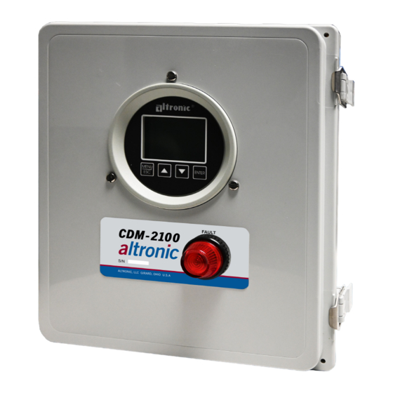
- Page 1 Operating Manual CDM-2100 Differential Pressure Monitor Form CDM-2100 OM 3-21...
- Page 2 FIG. 1 MOUNTING DIMENSIONS .................... 16 FIG. 2 WIRING DIAGRAM, CUSTOMER CONNECTIONS ............17 FIG. 3 FLOW CHART ....................... 18 FIG. 4 CDM-2100 SYSTEM DIAGRAM..................19 FIG. 5 RS-485 COMMUNICATIONS: PC HOOK-UP ..............20 FIG. 6 RS-485 COMMUNICATIONS: MULTIPLE SLAVE UNITS ..........20 CDM-2100 OM 3-21 All rights reserved ©...
-
Page 3: Mounting The Panel
When each port of the differential pressure transmitter is placed across the catalyst element, it sends an electronic signal back to the CDM-2100. This signal represents the amount of pressure drop across the catalyst element. -
Page 4: Keypad Description
NEC and local authority. 6.0 KEYPAD DESCRIPTION The CDM-2100 gauge features a four-key front keypad which is used to view or change the setpoint values, configure and calibrate the gauge. The front panel keys are MENU/ESC, ENTER, and , ... -
Page 5: Initial Configuration
8.0 INITIAL CONFIGURATION 8.1 The CDM-2100 is pre-configured for measuring the differential catalyst pressure NOTE: The splash screen can be using the Altronic differential pressure transmitter. All of the basic labels and displayed at anytime from a home configuration are already complete for the user to start monitoring. However, screen by pressing both the up and there are site specific parameters that should be updated. - Page 6 Be sure that the sensor type and the engineering units of the calibrator match the type and engineering units of the instrument before performing a calibration. CDM-2100 OM 3-21 All rights reserved © ALTRONIC, LLC 2021...
- Page 7 8.4.2 The CDM-2100 gauge has a feature that allows a slight adjustment of either the zero or span values individually. This type of calibration can be used to “tweak” the readout to match that of a known value without actually performing a formal calibration procedure.
-
Page 8: Previous Menu
PREVIOUS MENU COMMUNICATIONS 8.6.1 The CDM-2100 gauge is part of a system that has been carefully designed to easily interface to popular computers, terminals, programmable controllers and Altronic instruments. Modbus RTU is the protocol used in the CDM- 2100. A Modbus register list with register numbers and descriptions of each register can be found in section 10.0. - Page 9 To gain access to the protected menus without having to enter a password, turn protection OFF. If the incorrect password is entered, the display will return to the menu denying access to the protected menu. CDM-2100 OM 3-21 All rights reserved © ALTRONIC, LLC 2021...
-
Page 10: Node Number
9.0 RS-485 COMMUNICATIONS The CDM-2100 gauge is part of a system that has been carefully designed to easily interface to popular computers, terminals, programmable controllers and Altronic instruments. The gauge communicates in the Modbus RTU protocol. MASTER/SLAVE OPERATION: The gauge’s RS-485 communication system is designed as a master/slave system;... - Page 11 SWITCH 1 STATE 0=SHELF 1=FAILSAFE 00019 SWITCH 1 TYPE 0=NON-LATCH 1=LATCHING 00020 RESERVED 00024 00025 SWITCH 2 RESET 1=RESET 00026 SWITCH 2 STATE 0=SHELF 1=FAILSAFE 00027 SWITCH 2 TYPE 0=NON-LATCH 1=LATCHING CDM-2100 OM 3-21 All rights reserved © ALTRONIC, LLC 2021...
- Page 12 SWITCH 2 Lo Hysteresis Timer (0.1 increments) 30019 CHANNEL 1 MAX (float) (msw) 30020 CHANNEL 1 MAX (float) (lsw) 30021 CHANNEL 1 MIN (float) (msw) 30022 CHANNEL 1 MIN (float) (lsw) CDM-2100 OM 3-21 All rights reserved © ALTRONIC, LLC 2021...
- Page 13 40019 Range HI (float) (msw) 40020 Range HI (float) (lsw) 40021 Volt HI (float) (msw) 40022 Volt HI (float) (lsw) 40023 Range LO (float) (msw) 40024 Range LO (float) (lsw) CDM-2100 OM 3-21 All rights reserved © ALTRONIC, LLC 2021...
- Page 14 SWITCH 1 Setpoint Hi (float) (lsw) 40103 SWITCH 1 Setpoint Lo (float) (msw) 40104 SWITCH 1 Setpoint Lo (float) (lsw) 40105 SWITCH 1 Setpoint Differential (float) (msw) 40106 SWITCH 1 Setpoint Differential (float) (lsw) CDM-2100 OM 3-21 All rights reserved © ALTRONIC, LLC 2021...
- Page 15 SWITCH 2 Setpoint Hi (float) (lsw) 40111 SWITCH 2 Setpoint Lo (float) (msw) 40112 SWITCH 2 Setpoint Lo (float) (lsw) 40113 SWITCH 2 Setpoint Differential (float) (msw) 40114 SWITCH 2 Setpoint Differential (float) (lsw) CDM-2100 OM 3-21 All rights reserved © ALTRONIC, LLC 2021...
- Page 16 FIG. 1 MOUNTING DIMENSIONS 13.21 13.34 335.5 338.9 4.28 4.28 108.8 108.8 11.34 287.9 12.05 8.30 7.28 210.8 3.90 99.1 1.06 26.9 THRU .88 22.2 THRU 2.76 CDM-2100 OM 3-21 All rights reserved © ALTRONIC, LLC 2021...
- Page 17 FIG. 2 WIRING DIAGRAM, CUSTOMER CONNECTIONS CDM-2100 OM 3-21 All rights reserved © ALTRONIC, LLC 2021...
- Page 18 FIG. 3 FLOW CHART CDM-2100 OM 3-21 All rights reserved © ALTRONIC, LLC 2021...
- Page 19 FIG. 4 CDM-2100 SYSTEM DIAGRAM CDM-2100 OM 3-21 All rights reserved © ALTRONIC, LLC 2021...
- Page 20 FIG. 5 RS-485 COMMUNICATIONS: PC HOOK-UP FIG. 6 RS-485 COMMUNICATIONS: MULTIPLE SLAVE UNITS CDM-2100 OM 3-21 All rights reserved © ALTRONIC, LLC 2021...
Need help?
Do you have a question about the CDM-2100 and is the answer not in the manual?
Questions and answers