Advertisement
Quick Links
ALTRONIC UNIVERSAL TEMPERATURE SCANNER
DSM-43900DUS
CAUTION: The DSM-43900DUS universal temperature scanners are suitable for use in Class I,
Groups C & D, Division 1 and 2 hazardous locations when installed in accordance with
these instructions.
The thermocouple leads connected to this device operate at a very low voltage and
power levels and MUST NOT CONTACT any external voltage source. Damage to the
system will result from connection between the thermocouple and the ignition system
or any AC or DC power source.
WARNING: DEVIATION FROM THESE INSTALLATION INSTRUCTIONS MAY LEAD TO
IMPROPER OPERATION OF THE MONITORED MACHINE WHICH COULD CAUSE PERSONAL
INJURY TO OPERATORS OR OTHER NEARBY PERSONNEL.
1.0 DESCRIPTION
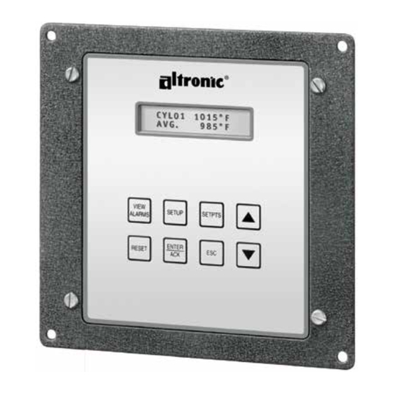
1.1 The Altronic DSM-43900DUS universal temperature scanner is an electronic instrument
designed to monitor temperatures using industry standard type J or K thermocouples.
Automatic cold junction compensation is built-in. Three models DSM-43908 (8 channels),
DSM-43916 (16 channels) and DSM-43924 (24 channels) are available. The temperature
scanner uses a microcontroller to process the input signal and a nonvolatile memory to store
the setup and setpoint values. A 2x16 character LCD displays the channel number and the
numeric temperature value in °F or °C. A front mounted keypad serves as the user interface.
The instrument can read type J thermocouples between !76°F and 1382°F (!60°C and
750°C) and type K thermocouples between !76°F and +1472°F (!60°C and 800°C).
1.2 Each of the input channels may have 4 individual user established temperature setpoints that
can be adjusted using the keypad - a high and low alarm and a high and low shutdown.
Alternatively, the user may assign a selected number of channels (2 min.) to a group with a
common set of 6 setpoints (high, low and differential alarm and high, low and differential
shutdown) with the remaining channels having 4 individual setpoints as described in the
preceding sentence. There are two configurable output switches, one for alarms and one for
shutdowns. When the temperature has exceeded its setpoint value, a solid state output
switch turns on/off to the switch common, and a first setpoint and channel number LCD
indicators turn on. All setpoint changes are performed through the keypad or through RS-485
communications.
1.3 The DSM-43900DUS universal temperature scanner is designed to be versatile and simple
to use. Type J or K thermocouples and °F or °C units can be selected via the keypad. Either
automatic or manual scan functions can be selected. An alarm log is available for the first
four faults. RS-485 serial communications allows data and alarm status to be communicated
to other devices. An escape key is provided to permit the user to exit any setup function and
return to the normal display. A programmable software filter is also provided which can be
used to stabilize readings where the thermocouple signal is fluctuating. Calibration can be
performed using the keypad. Factory default configurations, including factory calibration
settings, can be recalled for easy setup.
INSTALLATION INSTRUCTIONS
FORM DSM43900 II 7-04
Advertisement

Related Manuals for Altronic DSM-43900DUS


Summary of Contents for Altronic DSM-43900DUS
- Page 1 INSTALLATION INSTRUCTIONS DSM-43900DUS FORM DSM43900 II 7-04 CAUTION: The DSM-43900DUS universal temperature scanners are suitable for use in Class I, Groups C & D, Division 1 and 2 hazardous locations when installed in accordance with these instructions. The thermocouple leads connected to this device operate at a very low voltage and power levels and MUST NOT CONTACT any external voltage source.
- Page 2 2.0 THERMOCOUPLES 2.1 The DSM-43900DUS universal temperature scanner is designed to operate with industry standard, grounded or ungrounded, type J or K thermocouples. Ungrounded thermocouples are recommended where possible. 3.0 MOUNTING 3.1 Mount the universal temperature scanner inside a control panel or to a suitable flat surface so that the display is at a convenient viewing height.
-
Page 3: Initial Operation
9004/51-206-100-00; follow the installation instructions supplied with the barrier. B. The switch outputs, if used, must be connected to the sensor inputs of an Altronic DA, or DD annunciator system with the 690 series power supply. The annunciator system must be CSA certified for the designated hazardous area. - Page 4 6.0 NORMAL OPERATION 6.1 When the DSM-43900DUS universal temperature scanner is in the "normal" mode, it displays the channel number (“CH. XX”) with the temperature value in °F or °C (1st line) and (2nd line) the status of the system. The status indicators are: “TIMER: T1 2 3 4"...
-
Page 5: Keypad Description
šššššššššššššš 8.0 KEYPAD DESCRIPTION 8.1 The DSM-43900DUS universal temperature scanner contains an eight-key front keypad which is used to view or change the setpoint values and to configure and calibrate the scanner. The eight front panel keys are VIEW ALARMS, RESET, SETUP, ENTER/ACK, SETPTS, ESC, and •, –... -
Page 6: Default Factory Settings
8.2 and 8.6 above are “H1” for high and “L1” for low. 9.0 DEFAULT FACTORY SETTINGS 9.1 The DSM-43900DUS universal temperature scanner contains default settings that are available to the user anytime during the life of the instrument. Upon receipt, the universal temperature scanner is set to one of these settings. - Page 7 9.3 DEFAULT SETTINGS - Listed below are the factory default settings stored in permanent memory. UNITS: Degrees F (°F) or Degrees C (°C) DISPLAY SCAN: Manual DISPLAY FILTER: 230 out of 255 NUMBER O F CHANNELS: 8, 12 or 24 channels PROTEC TION STATUS: Protection is OFF (Allow setpoints to be changed .) NODE NUMBER:...
-
Page 8: Filter Value
10.3 "AUTO SCAN” - Allows the user to display automatically, or manually, the selected number of points. The scan starts with channel 01 and progresses in numerical order to the last channel selected in configuration. In manual scan, the device continually displays the temperature value of one channel at a time. - Page 9 10.11 "OUTPUT 1 / OUTPUT 2" OUTPUT SWITCH STATE - The options for each of the output switches are fail safe or shelf state, and latching or non-latching. Shelf state is when the outputs are in the same condition with no faults as when unpowered; fail-safe is when they are opposite.
- Page 10 11.2 For the channels in common groups 1 and 2, there are 6 common, adjustable setpoints which can be set anywhere within the range of the scanner or OFF. The setpoints are L1 (low 1), L2 (low 2), H1 (high 1), H2 (high 2), D1 (differential 1) and D2 (differential 2). Setpoints L1, H1 and D1 will trip output switch 1, and setpoints L2, H2 and D2 will trip output switch 2.
- Page 11 NOTE: When in the setpoints mode, the previous setpoint values are monitored, and the new value is monitored only after the ENTER/ACK key is pressed. If no key is pressed for 30 seconds, the display will return to the normal mode and the configuration will revert back to the previous parameters.
- Page 12 11.6 START-UP TIMERS - As stated above, the start-up timers initiate when the sense line is released or when RESET is initiated. The normal display shows the timer status on the second line by displaying the active timer(s), T1, T2, T3, and or T4. When each timer that is used times out, it will be removed from the display.
- Page 13 12.3 The DSM-43900DUS universal temperature scanner has a feature that allows a slight adjustment of either the zero or span values individually. This type of calibration can be used to "tweak" the readout to match that of a known value without actually performing a formal calibration procedure.
- Page 14 The DSM-43900DUS universal temperature scanner is part of a system that has been carefully designed to easily interface to popular computers, terminals, programmable controllers and future Altronic instruments. The data and status on any channel as well as the setpoint values can be read remotely. The setpoints can also be adjusted remotely.
- Page 15 RX, TX INDICATORS - An RX and TX (receive and transmit) LED is visible on the back of the DSM-43900DUS unit to indicate when the unit is either receiving or transmitting data. 14.10 CONNECTING TO A PC - When connecting the DSM-43900DUS universal temperature scanner to the RS-232 port on a PC, an RS-232 to RS-485 converter must be used for the communication interface.
- Page 16 COMMAND HEADER ">" (3Eh) - Each command must begin with the command header sometimes referred to as a prompt character. The ASCII character used is the ">" which means that a command message will be sent from the master to the slave. START OF TEXT "("...
- Page 17 A plus sign must be used for a setpoint value of zero (Ex: +0000.). Listed are the 2 digit number codes and channel numbers corresponding to the eighty setpoints setpoint codes go from 01 to 80 and correspond as follows: 01 = CH01 H1 Channel one, high setpoint one 02 = CH01 L1...
- Page 18 RS, CS, CA, RR commands 100 msec. max. An NAK error response will be sent by the DSM-43900DUS unit when it has received a command with an error in the message. All commands must be of the format above; all letters must be uppercase.
- Page 19 14.13 CHECKSUMS - Two additional commands are provided so that the user may enable or disable the communication checksum routines. When enabled, the messages include an error-checking checksum that is based upon an Exclusive-Or, Modulo 100 conversion sum of the characters in the message string between and including the start of text "(" character and the end of text ")"...
- Page 20 14.14 REMOTE OPERATOR INTERFACE (ROI), ASCII - The DSM-43900 contains a feature that allows the functions of the keypad to be accessed remotely. The returned data is that of the LCD display of the DSM-43900. This feature allows for any function that can be performed locally at the keypad to be implemented remotely.
- Page 21 TIMER REGISTERS (FUNCTION CODE 1) ADDRESS DESCRIPTION OF FUNCTION CHAN NEL 01 H1 TIMER SELECT BIT 0 (T1) CHAN NEL 01 H1 TIMER SELECT BIT 1 (T2) CHAN NEL 01 H1 TIMER SELECT BIT 2 (T3) CHANNEL 01 H1 TIMER SETPOINT ON/OFF CHAN NEL 01 L1 TIMER SELEC T BIT 0 (T1) CHAN NEL 01 L1 TIMER SELEC T BIT 1 (T2) CHAN NEL 01 L1 TIMER SELEC T BIT 2 (T3)
- Page 22 INPUT STATUS (FUNCTION CODE 2) ADDRESS DESCRIPTION OF FUNCTION 10001 RESERVED 10002 RESERVED 10003 SW ITCH 2 FAULT (1 = FAULT) 10004 SW ITCH 1 FAULT (1 = FAULT) 10005 GLOBAL FAULT BIT (1 = FAULT) 10006 GLOBAL ARMED BIT (1 = ARMED) 10007 SENSE BIT (1 = ACTIVE) 10008...
- Page 23 INPUT REGISTERS (FUNCTION CODE 4) ADDRESS DESCRIPTION OF FUNCTION 30001 CH AN NE L 01 TE MP ER AT UR E IN DE GR EES KELVIN 30002 CH AN NE L 02 TE MP ER AT UR E IN DE GR EES KELVIN 30003 CH AN NE L 03 TE MP ER AT UR E IN DE GR EES KELVIN 30004...
- Page 24 HOLDING REGISTERS (FUNCTION CODE 3) ADDRESS DESCRIPTION OF FUNCTION 40001 INPUT SIGNA L DISPLAY FILTER (1-255) 40002 NOD E NUM BER (1-99) 40003 TIMER 1 (1-99) 40004 TIMER 2 (1-99) 40005 TIMER 3 (1-99) 40006 TIMER 4 (1-99) 40007 FAULT #1 (0 = CLEAR) 40008 FAULT #2 (0 = CLEAR) 40009...
- Page 25 15.2 IDENTIFICATION ( FUNCTION CODE 17): QUERY: NN 17 CRC CRC NN = node number, 17 = ID function code, CRC CRC = two byte Modbus RTU CRC. RESPONSE: NN 17 18 00 RC Vm M M / DD / Y Y D S M43924 CRC CRC NN = node number, 17 = ID function code, 18 = number of bytes to follow, RC = Run Condition, VM = Version Major, Vm = Version minor, ASCII string that is the firmware date, DSM-43924 ASCII string indicating the DSM-43924 instrument, CRC CRC = two byte...
- Page 26 15.4 READ COIL LABEL ( FUNCTION CODE 101): QUERY: NN 101 ADH ADL CRC CRC NN = node number, 101 = function code, ADH:ADL = Two byte address of desired coil (1-320), CRC CRC = two byte Modbus RTU CRC. RESPONSE: NN 101 30 A S C I I S T R I N G CRC CRC NN = node number, 101 = function code, 30 = number of bytes to follow, ASCIISTRING =...
- Page 27 FIG. 2 - DSM-43900DUS CONFIGURATION WORKSHEET FIG. 3 - DSM-43900DUS FLOWCHART FIG. 4 - GENERAL ELECTRICAL CONNECTIONS FIG. 5 - WIRING DIAGRAM, ALTRONIC ANNUNCIATOR SYSTEMS FIG. 6 - WIRING DIAGRAM, DC RELAYS FIGS. 7,8 - WIRING DIAGRAM, RS-485 COMMUNICATIONS FIGS. 9, 10, 11 - WIRING DIAGRAM, SENSE LINE...
Need help?
Do you have a question about the DSM-43900DUS and is the answer not in the manual?
Questions and answers