
Related Manuals for EPA SM-Ethernet

Summary of Contents for EPA SM-Ethernet
- Page 1 SM-Ethernet Solutions Module Commander GP User Guide Unidrive SP Commander SK Digitax ST Mentor MP Affinity Distributor for:...
- Page 2 EPA Drives Thank you for choosing to work with EPA! EPA - your competent partner for Nidec / Control Techniques when it comes to individual service & comprehensive services. If you have any questions about the product, please feel free to call us: Tel: +49 (0)6181 –...
- Page 3 Original Instructions For the purposes of compliance with the EU Machinery Directive 2006/42/EC, the English version of this manual is the Original Instructions. Manuals in other languages are Translations of the Original Instructions. Documentation Manuals are available to download from the following locations: http://www.drive-setup.com/ctdownloads The information contained in this manual is believed to be correct at the time of printing and does not form part of any contract.
- Page 4 Copyright The contents of this publication are believed to be correct at the time of printing. In the interests of a commitment to a policy of continuous development and improvement, the manufacturer reserves the right to change the specification of the product or its performance, or the contents of the guide, without notice. All rights reserved.
-
Page 5: Table Of Contents
Electrical installation ............. 14 SM-Ethernet module information ..............14 Cabling considerations ................. 15 Module grounding ..................15 SM-Ethernet cable shield connections ............15 Cable ......................15 Maximum network length ................15 Minimum node to node cable length ............. 16 Network topology ..................16 Typical network connections ................ - Page 6 Setting the IP address .................. 24 5.12 Setting the subnet mask ................25 5.13 Setting the default gateway ................26 5.14 SM-Ethernet baud rate ................. 27 5.15 DHCP (Dynamic Host Configuration Protocol) ..........27 5.16 SM-Ethernet operating status ............... 28 5.17 Re-initialising SM-Ethernet ................
- Page 7 12.5 Modbus TCP/IP (CT implementation) ............110 12.6 Supported Modbus function codes ............. 112 12.7 Modbus exception codes ................116 Quick reference ..............117 13.1 Complete parameter reference ..............117 Glossary of terms ..............123 SM-Ethernet User Guide Issue: 7...
-
Page 8: Safety Information
(EMC) regulations. Particular attention must be given to the cross-sectional areas of conductors, the selection of fuses or other protection, and protective ground (earth) connections. This guide contains instructions for achieving compliance with specific EMC standards. SM-Ethernet User Guide Issue: 7... -
Page 9: Electrical Hazards
Access to equipment Access must be restricted to authorized personnel only. Safety regulations which apply at the place of use must be complied with. SM-Ethernet User Guide Issue: 7... -
Page 10: Environmental Limits
It is the responsibility of the installer to ensure that the equipment or system into which the product is incorporated complies with the relevant EMC legislation in the place of use. SM-Ethernet User Guide Issue: 7... -
Page 11: Introduction
Introduction Features The SM-Ethernet is a Solutions Module that can be used on the following products to provide Ethernet slave connectivity: • Unidrive SP • Commander SK • Affinity • Digitax ST • Mentor MP With the exception of Commander SK, it is possible to use more than one SM-Ethernet module or a combination of SM-Ethernet and other Solutions Modules to add additional functionality such as extended I/O, gateway functionality, or additional PLC features. -
Page 12: Software Statement
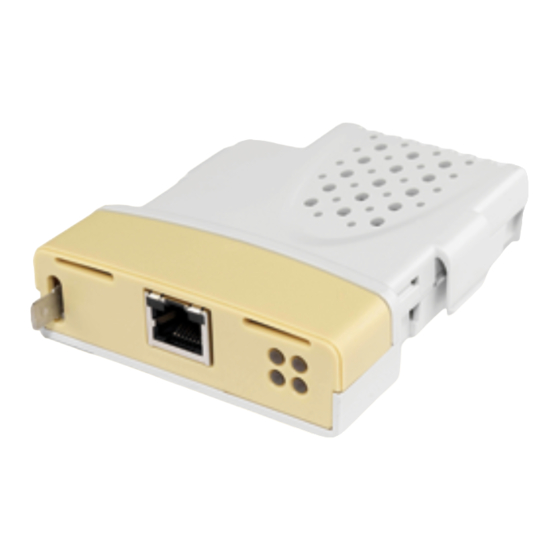
Firmware version SM-Ethernet 1736 Firmware: 02.00.02 Hardware Issue: issue Approvals number Ser No : 8000001001 MAC: 00:00:1E:06:C8:2B Serial number MAC Address 2. The color coding across the front of the Solutions Module. SM-Ethernet being beige. SM-Ethernet User Guide Issue: 7... -
Page 13: Product Conformance
Example: A date code of 1710 would correspond to week 10 of year 2017. Product conformance SM-Ethernet complies with IEEE 802.3 and meets the isolation requirements of safety standard EN50178. Conventions used in this guide The configuration of the host drive and Solutions Module is done using menus and parameters. -
Page 14: Mechanical Installation
Solutions Module slot located on the drive until it clicks into place (2). Note that some drives require a protective tab to be removed from the Solutions Module slot. For further information, refer to the appropriate drive manual. SM-Ethernet User Guide Issue: 7... -
Page 15: Electrical Installation
SM-Ethernet provides a standard RJ45 UTP/STP (Un-shielded/Shielded Twisted Pair) connection to a 10Mbs or 100Mbs Ethernet system. In addition to the RJ45 connector a grounding tag is supplied for supplementary bonding. SM-Ethernet provides 4 diagnostic LEDs for status and information purposes. -
Page 16: Cabling Considerations
Module grounding SM-Ethernet is supplied with a grounding tag on the module that should be connected to the closest possible grounding point using the minimum length of cable. This will greatly improve the noise immunity of the module. -
Page 17: Minimum Node To Node Cable Length
The setup and installation of the firewall should be done by a suitably qualified engineer and is beyond the scope of this document. SM-Ethernet User Guide Issue: 7... -
Page 18: Typical Network Connections
4.9.1 Single PC to SM-Ethernet To connect a PC to the SM-Ethernet using the default setting of Pr MM.43 requires a crossover cable. This allows the two devices to communicate without the need to change any settings on SM-Ethernet or the use of a switch or hub. - Page 19 Single PC to multiple SM-Ethernet using a single switch Connecting multiple SM-Ethernet modules should be done using an industrial grade switch. Each SM-Ethernet or PC is connected to the switch using a standard RJ45 lead (patch lead). Figure 4-4 Single PC to multiple SM-Ethernet modules using a switch...
-
Page 20: Getting Started
The issue of addressing becomes important when connecting multiple networks together or connecting to the Internet where there is a strong possibility of duplication of addresses if a scheme is not followed. SM-Ethernet User Guide Issue: 7... -
Page 21: Addressing Etiquette
Using the subnet mask it is possible to modify the IP addressing such that the ratio of NOTE subnets and host addresses may be changed. This gives you the facility to “adjust” standard classes to suit your specific requirements. SM-Ethernet User Guide Issue: 7... -
Page 22: Generating The Complete Address
IP address is bit-wise ANDed with the subnet mask. Figure 5-1 shows how the IP address and subnet mask are used to determine the subnet address and the host address. SM-Ethernet User Guide Issue: 7... -
Page 23: Dhcp Considerations
Ethernet. Any leased addresses should be leased permanently to prevent IP address changes. If SM-Ethernet is configured to use DHCP and the module requires exchanging, the new NOTE SM-Ethernet module will have a different MAC address and hence the DHCP server will issue the new module with a different IP address. -
Page 24: Set-Up Flow Chart
Pr MM.32 = ON Check data rate. See Chapter 5 (Pr MM.04) Ensure PC is on the same subnet or the default See Chapter 5 gateway on the drive & PC are set SM-Ethernet User Guide Issue: 7... -
Page 25: Setting The Ip Address
5.11 Setting the IP address The SM-Ethernet IP address is formed by taking the component parts of the address from parameters Pr MM.10 to Pr MM.13 and combining them as in Figure 5-2. The address is then used in conjunction with the subnet mask. -
Page 26: Setting The Subnet Mask
5.12 Setting the subnet mask The SM-Ethernet subnet mask is formed by taking the component parts of the subnet mask from parameters Pr MM.14 to Pr MM.17 and combining them as in Figure 5-3. The subnet mask is then used in conjunction with the IP address. -
Page 27: Setting The Default Gateway
5.13 Setting the default gateway The SM-Ethernet’s default gateway is formed by taking the component parts of the default gateway from parameters Pr MM.18 to Pr MM.21 and combining them as in Figure 5-4. The default gateway is then used in conjunction with the IP address and subnet mask to locate hosts on different subnets. -
Page 28: Sm-Ethernet Baud Rate
0 to 2 Access SM-Ethernet can be set to automatically detect the baud rate or be fixed at either 10Mbs or 100Mbs. Pr MM.44 will indicate the data rate that is being used by the SM-Ethernet. Table 5.4 SM-Ethernet baud rate Pr MM.04... -
Page 29: Sm-Ethernet Operating Status
SM-Ethernet, a value of zero indicates that SM-Ethernet is initialised and ready to communicate. If this parameter is a negative value this indicates that the module is initialising or there is a fault. If this value is still negative after 3 minutes see section 11.5.1 SM-Ethernet diagnostic information on page 99. 5.17... -
Page 30: Saving Parameters To The Drive
Press the red RESET button. The drive will store all parameters (except Menu 20), but the operation of the SM- Ethernet will not be affected. Changes made to the SM-Ethernet configuration parameters will not take effect until the SM-Ethernet is re-initialised. -
Page 31: Protocols
PC/PLC considerations If the subnet of the host PC/PLC is different to the subnet of SM-Ethernet, then both SM-Ethernet and the PC/PLC must be configured with the address of a gateway that allows communication between the two devices. -
Page 32: Web Pages (Http)
FTP will allow custom web page changes on SM-Ethernet. If an appropriate network infrastructure exists it will be possible to perform these updates remotely. SM-Ethernet has a basic file system that will allow the user to upload files. The following facilities are supported: •... -
Page 33: Ethernet/Ip
SM-Ethernet (v01.03.00 and later) supports the EtherNet/IP protocol and conforms to the EtherNet/IP adaptation of the Common Industrial Protocol (CIP) Specification. This is the same upper-layer protocol and object model as used in DeviceNet. The SM-Ethernet module will operate as a slave device and the following functionality is supported. •... - Page 34 This timeout is defined by the EtherNet/IP protocol and is configured in the PLC master. If enabled, then SM-Ethernet will monitor the data traffic and if data is not received within the specified time, it will force a drive trip (SL1.Er, SL2.Er or SL3.Er, depending on which slot the solutions module is installed to, for Unidrive SP/Affinity/Digitax ST/ Mentor MP or SL.Er for Commander SK) and a trip code in Pr MM.50 of 50.
- Page 35 Whether consistency is enabled or not, data will always be consistent for an individual parameter, i.e. all 4 bytes of a 32 bit value will be consistent. The trigger parameter is a parameter that is used by SM-Ethernet to allow cyclic param- NOTE eters to be written and is configured from the EtherNet/IP sub-menu of the PROTO- COLS menu.
- Page 36 6.7.10 Configuring SM-Ethernet cyclic parameters on page 35. 6.7.10 Configuring SM-Ethernet cyclic parameters In order to use cyclic data over EtherNet/IP, SM-Ethernet must be configured to map the required parameter data to the assembly object. Object 100 (0x64) is used for reading parameters and object 101 (0x65) is used for writing parameters.
- Page 37 Figure 6-1 SM-Ethernet parameter mapping configuration Parameter mapping table. Parameter list. A single parameter may be selected by “dragging” it from the parameter list on the left side of the page to the parameter mapping table on the right side of the page or, alternatively, “double-clicking”...
- Page 38 If a different length is required then a new Ethernet module must be created. In order to communicate with the SM-Ethernet, the PLC must have the SM-Ethernet IP address set correctly as illustrated in Figure 6-2.
- Page 39 Control Word Description Set this bit to command the drive to run in the forward RunFwd direction. A 0 to 1 transition will reset the drive if the drive was in a FaultRst trip state. SM-Ethernet User Guide Issue: 7...
- Page 40 The PLC or scanner must be configured for 4 output bytes (or 2 output words) if this assembly object is to be used. Table 6.7 Extended speed control Data word Function Word 0 Extended control word. Word 1 Speed reference (SpeedRef). SM-Ethernet User Guide Issue: 7...
- Page 41 The PLC or scanner must be configured for 6 output bytes (or 3 output words) if this assembly object is to be used. Table 6.8 Basic speed and torque control Data Word Function Word 0 Basic control word. Word 1 Speed reference (SpeedRef). Word 2 Torque reference (TorqueRef). SM-Ethernet User Guide Issue: 7...
- Page 42 The torque reference word utilises 2 bytes (16 bits) as shown below. TorqueRef (high byte) TorqueRef (low byte) For more information on the setting of the torque reference see section 6.7.26 AC/DC Drive object on page 62. SM-Ethernet User Guide Issue: 7...
- Page 43 The speed reference word utilises 2 bytes (16 bits) as shown below. SpeedRef (high byte) SpeedRef (low byte) For more information on the setting of the speed reference see section 6.7.26 AC/DC Drive object on page 62. SM-Ethernet User Guide Issue: 7...
- Page 44 Speed feedback (SpeedActual) The speed feedback word utilises 2 bytes (16 bits) as shown below. SpeedActual (high byte) SpeedActual (low byte) For more information on the speed feedback see section 6.7.26 AC/DC Drive object on page 62. SM-Ethernet User Guide Issue: 7...
- Page 45 All other DriveType states, e.g. Scan, Orienting, 00000000 Vendor Specific Regen Active, etc. The individual bits of the low byte of the extended status word are described in Table 6.13 Extended status word (low byte) on page 45. SM-Ethernet User Guide Issue: 7...
- Page 46 The PLC or scanner must be configured for 6 input bytes (or 3 input words) if this assembly object is to be used. Table 6.14 Basic speed and torque feedback Data word Function Word 0 Basic status word Word 1 Speed feedback (SpeedActual). Word 2 Torque feedback (TorqueActual). SM-Ethernet User Guide Issue: 7...
- Page 47 The PLC or scanner must be configured for 6 input bytes (or 3 input words) if this assembly object is to be used. Table 6.15 Basic speed and torque feedback Data word Function Word 0 Extended status word. Word 1 Speed feedback (SpeedActual). Word 2 Torque feedback (TorqueActual). SM-Ethernet User Guide Issue: 7...
- Page 48 All other DriveType states, e.g. Scan, Orienting, 00000000 Vendor Specific Regen Active, etc. The individual bits of the low byte of the extended status word are described in Table 6.17 Extended status word (low byte) on page 48. SM-Ethernet User Guide Issue: 7...
- Page 49 Torque feedback (TorqueActual) The torque feedback word utilises 2 bytes (16 bits) as shown below. TorqueActual (high byte) TorqueActual (low byte) For more information on the torque feedback see section 6.7.26 AC/DC Drive object on page 62 SM-Ethernet User Guide Issue: 7...
- Page 50 UINT Revision USINT SerialNumber UDINT ProductName SHORT_STRING Vendor ID Name: VendorID 0x101 (257 Class 0x01 Default Instance 0x01 Data Type UINT Attribute 0x01 Access Returns the vendor ID code 0x101 (257 ) for Control Techniques. SM-Ethernet User Guide Issue: 7...
- Page 51 The major revision returned will be calculated from the formula: #11.29 * 3. Where #11.29 is the value of Pr 11.29 before the decimal point. e.g. For a value of “1.09” in Pr 11.29, the major revision returned is 3. SM-Ethernet User Guide Issue: 7...
- Page 52 Where #11.29 is the value of Pr 11.29 before the decimal point and Slot is the slot number that the SM-Ethernet module is installed in. e.g. For a value of “1.09” in Pr 11.29 and the SM-Ethernet module installed in slot 3, the value returned will be 5.
- Page 53 Returns 2 bytes to indicate the minor and sub-version revision numbers. If a basic generic EDS file is used then only the minor revision in the upper byte is returned as shown in Table 6.23 Basic revision on page 53. SM-Ethernet User Guide Issue: 7...
- Page 54 Attribute 0x06 Access Returns the least 3 significant bytes of the SM-Ethernet MAC address. The MAC address is set during production, and cannot be changed. This value is also displayed in Pr MM.35. This can be used to find the complete MAC address of the module by combining the NOTE numbers with 00:0D:1E:xx.xx.xx.
- Page 55 Access Returns 12 bytes (ASCII) to indicate the product name as a short string. The first byte specifies the number of following bytes that constitute the product name. The SM- Ethernet returns the string “SM-Ethernet”. 6.7.24 Motor data object Class: 0x28 (40 There are 2 instances of the Motor data object.
- Page 56 Returns or sets the motor type to be used by the drive for instance 1. Name: MotorType2 Class 0x28 Default Instance 0x02 Data Type USINT Attribute 0x03 Access Get/Set Returns or sets the motor type to be used by the drive for instance 2. SM-Ethernet User Guide Issue: 7...
- Page 57 Name: RatedVoltage2 Class 0x28 Default Pr 21.09 Instance 0x02 Data Type USINT Attribute 0x07 Access Get/Set Returns or sets the rated motor voltage in Volts for instance 2. This attribute is linked to Pr 21.09. SM-Ethernet User Guide Issue: 7...
- Page 58 Selects between Motor Map 1 and Motor Map 2. This attribute is linked to Pr 11.45. When this bit is set to 1, Motor Map 2 will be active. Any change in this attribute will be implemented when the drive is disabled. NOTE SM-Ethernet User Guide Issue: 7...
- Page 59 Get/Set Pr 6.42 (bit 1). RunRev Name: RunRev Class 0x29 Default Instance 0x01 Data Type USINT Attribute 0x04 Access Get/Set Set to 1 to run the drive in the reverse direction. Get/SetPr 6.42 (bit 3). SM-Ethernet User Guide Issue: 7...
- Page 60 RunningRev Class 0x29 Default Instance 0x01 Data Type USINT Attribute 0x08 Access Indicates that the drive is running in the reverse direction. This attribute will be set to 1 when Pr 10.14=1 and Pr 10.02=1. SM-Ethernet User Guide Issue: 7...
- Page 61 Get Pr 10.19. FaultRst Name: FaultRst Class 0x29 Default Instance 0x01 Data Type USINT Attribute 0x0C Access Get/Set Resets the drive from a tripped condition. Sets Pr 10.38 to 100 on a 0 to 1 transition. SM-Ethernet User Guide Issue: 7...
- Page 62 Table 6.31, then SM-Ethernet will return the ODVA fault code as shown in Table 6.31 below. If the drive fault code is not listed in Table 6.31 then SM-Ethernet will return the ODVA code as follows: ODVA Fault Code = 0x1000 + drive fault code.
- Page 63 Name: NetRef Class 0x2A Default Instance 0x01 Data Type USINT Attribute 0x04 Access Get/Set Selects the source of the speed reference. Get/SetPr 6.42 bit 8 0 = analog speed reference. 1 = digital speed reference. SM-Ethernet User Guide Issue: 7...
- Page 64 Device State Conflict (0x10) Regen (4) Pr 11.31 will never be changed by setting the DriveMode attribute. An error (0x10) will NOTE be generated if the requested DriveMode value does not correspond to the current DriveType operating mode. SM-Ethernet User Guide Issue: 7...
- Page 65 Sets the load (torque) reference as % of rated motor load (torque). This attribute has 1 decimal place precision, so a value of 1000 represents 100.0% load. Set Pr 4.08 = TorqueRef / 10. Get TorqueRef = Pr 4.08 * 10. SM-Ethernet User Guide Issue: 7...
- Page 66 RefFromNet Name: RefFromNet Class 0x2A Default Instance 0x01 Data Type USINT Attribute 0x1D Access Indicates the source of the speed reference. TRUE if Pr 1.49 = 3 and Pr 1.50 = 1. FALSE otherwise. SM-Ethernet User Guide Issue: 7...
- Page 67 0x82 (130 130 - 157 Menus of option module (if installed) in slot 2. 0x9D (157 0xA0 (160 160 - 187 Menus of option module (if installed) in slot 3. 0xBB (187 0xC8 (200 Menu 0. SM-Ethernet User Guide Issue: 7...
- Page 68 6.7.28 TCP/IP Interface object Class: 0xF5 (245 The TCP/IP Interface object provides the mechanism to configure the SM-Ethernet TCP/IP network interface. Examples of configurable items include the device IP address, network mask and gateway address. This object is normally configured by the PLC software.
-
Page 69: Web
Web page basics Connecting to SM-Ethernet If you are using DHCP, all settings on the SM-Ethernet module will be configured by the network DHCP server, you can confirm this is working by checking the IP address has been correctly configured in parameters Pr MM.10 to Pr MM.13. In order to communicate, the PC must be on the same subnet as the drive or you must have a gateway specified for the host PC and the SM-Ethernet module. -
Page 70: Web Page Menu Structure
Web page menu structure The menu structure on SM-Ethernet is logically grouped by function to allow for ease of navigation. Figure 7-1 Web page structure SM-Ethernet User Guide Issue: 7... - Page 71 User menu parameter summary - details the parameters that the user has previously defined to appear in this menu. • Drive name - this is the name allocated to SM-Ethernet during set-up. • Language packs installed - this area of the screen will indicate whether any languages (other than English) are installed in the module.
- Page 72 7.2.2 Logging in Before you can view any additional screens you must login to SM-Ethernet. The default username is root and the default password is ut72. The root username cannot be changed, but the password should be changed to prevent unauthorized access to SM- Ethernet.
- Page 73 Homepage - Displays information about the drive and user configured parameters. Module Info - Shows technical information about SM-Ethernet. This information includes the MAC address, SM-Ethernet firmware version, the power-up time, file system availability and other parameters. Profile - Allows users to change passwords, languages and session timeout lengths.
- Page 74 Scheduled Events - Configure events to trigger at certain times or on certain event conditions, also configures the time source server. EtherNet/IP - Displays and allows editing of the EtherNet/IP settings and parameter mappings. SM-Ethernet User Guide Issue: 7...
- Page 75 Reset - Allows the module to be reset. 7.2.8 Help These pages provide a basic level of help on the features of the SM-Ethernet module. 7.2.9 Log-Out This option logs the current user out of the web pages.
-
Page 76: Ftp/Custom
FTP/custom pages Introduction SM-Ethernet gives you the facility to generate customised web pages (similar to HMI screens) that can be viewed using a web browser. Figure 8-1 shows one of the supplied custom web pages that can be used as a starting point for your own pages. -
Page 77: Custom Files
- contains the images for the custom pages, these may be added to if required. If these files are not present then please contact your supplier or local drive centre as the NOTE custom pages will need to be uploaded into the SM-Ethernet module using the FTP con- nection. SM-Ethernet User Guide... -
Page 78: Generating Your Own
You can access the pages directly as http:// WWW.XXX.YYY.ZZZ/FS/system/custom/index.htm (where WWW.XXX.YYY.ZZZ is the target SM-Ethernet module’s IP address). You must still be logged in to view these pages (some user accounts can be configured to be permanently logged in see section 10.6 Security levels on page 89). - Page 79 This is decoded as a single read of Pr 1.21 from the SM-Ethernet module with the address 129.111.0.136. For multiple parameters each parameter is separated by the underscore character as follows: http://129.111.0.136/US/1.21_1.24/dynamic/readparval.xml The response to the URL request above would be: <parameters>...
-
Page 80: Applications
Applications SM-Ethernet provides an alternative to the EIA-485 (RS-485) connections provided on the front of the drive. By using SM-Ethernet it is possible to communicate to the drive using the following range of Control Techniques products. • CTSoft. • CTScope •... - Page 81 Select the “Work with a drive” option and select the correct drive type followed by clicking on the “OK” button. From the navigation panel (Explorer) double click on the drive properties from the list as shown in Figure 9-2 Drive properties on page 80. Figure 9-2 Drive properties SM-Ethernet User Guide Issue: 7...
- Page 82 CTNet node address of the drive to be communicated with. For example, if the host drive has a SM-Ethernet installed in Slot 3 and a SM- Applications installed in Slot 2, to communicate to a drive with a CTNet node address of 5, a ”slot”...
-
Page 83: Ctscope
Support for the SM-Ethernet was included in CTSoft Version 01.05.00 and above. NOTE Support for using SM-Ethernet as a gateway to CTNet was included in CTSoft Version 01.06.01 and above. For communication to be established, the serial priority parameter Pr MM.37 must be set NOTE to ON in SM-Ethernet. - Page 84 2. A first drive hosting a single SM-Ethernet module with a single SM-Applications networked to a second CTNet enabled drive or Beckhoff bus coupler. 3. A first drive hosting two SM-Ethernet modules networked to a second CTNet drive hosting a single SM-Ethernet module.
- Page 85 (depending on the configured network settings). Figure 9-6 SyPTPro startup Figure 9-7 Drive communication settings For communication to be established, the serial priority parameter Pr MM.37 must be set NOTE to ON in SM-Ethernet. SM-Ethernet User Guide Issue: 7...
- Page 86 Figure 9-8 PC Communication settings 5. A graphical representation of the network is displayed. Figure 9-9, below, shows the third configuration type. A first drive hosting two SM-Ethernet modules networked to a second CTNet drive hosting a single SM-Ethernet module.
-
Page 87: Syptlite
OPC client then requests the updated value from the OPC server. The Control Techniques OPC server version 03.01.00 and above support the TCP/IP protocol used over Ethernet. For further information please contact the supplier of the drive. NOTE SM-Ethernet User Guide Issue: 7... -
Page 88: Security
By default, access to the drive over Ethernet is set to read/write access. By default, all services are available. This can be changed using Pr MM.36 (please see section 12.4.7 SM-Ethernet disable full access on page 108 for more information). 10.3.1 Disable Full Access The global write enable Pr MM.36 is set to 0 by default. -
Page 89: Account Management
4. Click on “New”. 5. Enter the details as requested in the menu. 6. Click “Apply” to finish. Following changes to the root account password SM-Ethernet should be reset using the NOTE reset function on the web pages. 10.5.1 Administrator accounts Administrator accounts are intended to provide a high level of access to the drive and module settings. -
Page 90: Security Levels
Super User Administrator 10.6.1 Limiting access SM-Ethernet will prevent a single user logging in more than once. A maximum of 5 simultaneous web based connections are possible. It is always possible for an administrator to log in. 10.6.2 Protocol authentication Certain protocols and services will require a user to authenticate using a password and a username. -
Page 91: Diagnostics
11.1 LED diagnostics The SM-Ethernet module is equipped with 4 LEDs on the front panel to aid in the diagnostics procedure. The functions of these LEDs are described in Table 11.1 LED functionality below. Table 11.1 LED functionality... -
Page 92: Diagnostic Flow Chart
11.2 Diagnostic flow chart SM-Ethernet User Guide Issue: 7... -
Page 93: Module Identification Parameters
Module identification parameters The basic SM-Ethernet configuration parameters can be accessed through the slot menu in the drive, Pr MM.xx where MM is the menu for SM-Ethernet in the host drive. 11.3.1 SM-Ethernet module ID code SM-Ethernet - module ID code... -
Page 94: Network Configuration Parameters
Pr MM.18 to Pr MM.21 respectively. When set to 1 the module will obtain this information from a DHCP server on the network. It is recommended that the MAC address of the SM-Ethernet module is used to allocate NOTE the IP address when DHCP is enabled. - Page 95 If DHCP is disabled, (MM.05=0), then this parameter should be saved (xx.00=1000 or xx.00=1001 if using a DC supply to power the drive) and activated by resetting the SM- Ethernet module (MM.32=ON). 11.4.7 SM-Ethernet IP subnet mask W subnet SM-Ethernet - IP subnet mask W...
- Page 96 If DHCP is disabled, (MM.05=0), then this parameter should be saved (xx.00=1000 or xx.00=1001 if using a DC supply to power the drive) and activated by resetting the SM- Ethernet module (MM.32=ON). 11.4.8 SM-Ethernet IP subnet mask X subnet SM-Ethernet - IP address X...
- Page 97 SM-Ethernet Duplex mode Default 0 (auto-detect) Pr MM.42 Range 0 to 2 Access This parameter determines how the duplex mode is set on SM-Ethernet. When set to 0 the module will auto-negotiate the duplex mode. SM-Ethernet User Guide Issue: 7...
- Page 98 If this parameter value is changed, then a module save should be performed (xx.00=1000 or xx.00=1001 if using a DC supply to power the drive) followed by resetting the SM-Ethernet module (MM.32=ON) to activate the change. 11.4.16SM-Ethernet enable auto-crossover detection...
- Page 99 SM-Ethernet module and takes the form U:V:W:X:Y:Z. The MAC address may be found on the product label on the outside of SM-Ethernet. This part of the MAC address will always be set to 00 as the first 3 bytes of the MAC address defines the manufacturer (Control Techniques).
-
Page 100: Diagnostic Parameters
SM-Ethernet module and takes the form U:V:W:X:Y:Z. The MAC address may be found on the product label on the outside of SM-Ethernet. The last 3 bytes form a unique serial number for a specific SM-Ethernet. - Page 101 Drive functional The module cannot communicate successfully with the host drive. test fail Thermal func- The thermal monitoring circuit on the SM-Ethernet module is not tional test fail working correctly. RAM test fail The SDRAM memory is not working correctly.
- Page 102 If the SM-Ethernet module does not initialise correctly when the drive is powered up, remove the power from the module, wait for the drive under-voltage (‘UU’) trip to disappear and re-apply the power, if the problem persists then the SM-Ethernet module should be changed.
- Page 103 Table 11.8 SM-Ethernet error codes Pr MM.50 Error Description EtherNet/IP Requested Packet Interval (RPI) timeout. EtherNet/IP stack has run out of memory. EtherNet/IP socket error. Maximum EtherNet/IP sessions reached. Maximum EtherNet/IP connections reached. EtherNet/IP request limit reached. Invalid configuration parameters.
-
Page 104: Advanced Features
The re-arm inhibit should be used to limit the number of mails that could be sent. This is important as SM-Ethernet has the potential to generate a high volume of email, if the trigger and re-arm conditions are continuously met. Setting this parameter will prevent messages from the same source being re-sent until the inhibit time has expired. -
Page 105: Scheduled Events
12.2 Scheduled events It is possible to configure the SM-Ethernet module to trigger certain events at certain times. The following examples show what can be achieved: • The SM-Ethernet module could be configured to send an email once every month. -
Page 106: Updating And Backup
12.2.3 Events A total of 10 events can be configured on each SM-Ethernet module. Each event has the following: • Summary - Each event can be given a descriptive name and independently enabled and disabled. To delete an event, tick the "Remove" option and then "APPLY". The "Missed Event Trip"... -
Page 107: Advanced Parameters
OFF/ON Access When set to ON and the SM-Ethernet module is reset (Pr MM.32 set to ON), the module will change it’s parameter values stored in the module’s local memory to default values. Any user changes or user web pages in the module will be lost. During this operation communications will be stopped. - Page 108 61, web page customisations, email settings, etc. This parameter should only be used to transfer a SM-Ethernet module to a different drive or when you wish to save any internal parameters directly (i.e. Pr 61.10). In order to save these parameters in the drive’s memory a drive save must be performed.
- Page 109 Access This will change the operating parameters for the module by copying the configuration from the backup copy in the SM-Ethernet module. During this operation communications will be stopped. The restored parameters will include menu 60 (Pr MM.xx), menu 61, web page customisations, email settings, etc. This will not save the current operating menu of the drive (Pr MM.xx), a drive save must be performed to...
- Page 110 Range OFF/ON Access It is not possible for the drive and SM-Ethernet module to support all of the available NOTE serial communication protocols simultaneously. This parameter, when set, allows SM- Ethernet to request the highest priority (not relevant for Commander SK).
-
Page 111: Modbus Tcp/Ip (Ct Implementation)
Modbus TCP/IP is one of the most widely supported Industrial Ethernet based protocols offering the functionality and simplicity of the Modbus protocol, combined with the flexibility of Ethernet. The SM-Ethernet implementation of Modbus TCP/IP uses a subset of the standard protocol provided by the Modbus organisation. - Page 112 SM-Applications module installed, the message will be routed to the SM-Applications module installed in the lowest slot number, if this is undesireable then the direct access parameters (menus 10x, 11x, 12x, etc) should be used. SM-Ethernet User Guide Issue: 7...
-
Page 113: Supported Modbus Function Codes
12.6 Supported Modbus function codes Table 12.3 below, details the supported Modbus function codes on SM-Ethernet. All function codes write to 16 bit registers only, to write to a 32 bit destination see section 12.6.1 Extended data types on page 112. - Page 114 For each byte in the PDU message, the MSB is transmitted first, followed by the LSB. NOTE The Modbus CRC bytes are not required when using TCP/IP due to the ethernet frame NOTE providing the error checking. SM-Ethernet User Guide Issue: 7...
- Page 115 For multiple registers, the register data is transmitted in ascending order, beginning with NOTE the start register address. The Modbus CRC bytes are not required when using TCP/IP due to the ethernet frame NOTE providing the error checking. SM-Ethernet User Guide Issue: 7...
- Page 116 For both the request and response message, the register data is transmitted in ascend- NOTE ing order, beginning with the start register address. The Modbus CRC bytes are not required when using TCP/IP due to the ethernet frame NOTE providing the error checking. SM-Ethernet User Guide Issue: 7...
-
Page 117: Modbus Exception Codes
This can occur if the module is trying to 0x06 SERVER_BUSY route a message but it cannot get control of the drive’s communications buffer. This occurs if there is no response to a 0x0B GATEWAY_PROBLEM_NO_RESPONSE routed message. SM-Ethernet User Guide Issue: 7... -
Page 118: Quick Reference
Quick reference 13.1 Complete parameter reference The table below lists all the SM-Ethernet set-up parameters that are required to configure the module. Table 13.1 SM-Ethernet parameter reference Parameter Default Cross reference Description Section 11.3.1 on Pr MM.01 Module ID code. - Page 119 Section 11.5.3 on Pr MM.50 Solutions Module error status. page 101 Section 11.3.2 on Pr MM.51 Solutions Module software sub-version. page 92 Table 13.2 SM-Ethernet virtual parameter reference Parameter Default Description Menu 60 Pr 60.00 Parameter zero. Pr 60.01 Module ID code.
- Page 120 Table 13.2 SM-Ethernet virtual parameter reference Parameter Default Description Pr 60.36 Disable full access. Pr 60.37 Reduce SP serial interface priority. Pr 60.38 User allocated group. Pr 60.39 Connection filtering. Pr 60.42 Duplex mode. Pr 60.43 Crossover detection. Pr 60.44 Actual baud rate.
- Page 121 Table 13.2 SM-Ethernet virtual parameter reference Parameter Default Description Secondary DNS server Z Pr 62.08 DNS2. Tertiary DNS server W Pr 62.09 DNS3. Tertiary DNS server X Pr 62.10 DNS3. Tertiary DNS server Y Pr 62.11 DNS3. Tertiary DNS server Z Pr 62.12...
- Page 122 Table 13.2 SM-Ethernet virtual parameter reference Parameter Default Description Pr 64.10 Connection status Pr 64.11 RPI timeout trip enable. Pr 64.12 Advanced EDS file enable. Pr 64.13 Motor 1 type. Pr 64.14 Motor 2 type. Pr 64.15 Primary input assembly object size (bytes).
- Page 123 Table 13.2 SM-Ethernet virtual parameter reference Parameter Default Description Pr 64.58 Input mapping parameter 39. Pr 64.59 Input mapping parameter 40. Pr 64.60 Output mapping parameter 1. Pr 64.61 Output mapping parameter 2. Pr 64.62 Output mapping parameter 3. Pr 64.63 Output mapping parameter 4.
-
Page 124: Glossary Of Terms
When a device sends or receives data the address is used to determine the source and the destination of the message. Assembly object: A software component within the SM-Ethernet which allows access to the parameters within the drive or which allows control and monitoring of the drive by using the EtherNet/IP protocol. - Page 125 IP subnet: A part of an IP network that consists of a range of addresses that may be accessed by all devices on the same network directly. LED: Light Emmiting Diode. Long word: A 32 bit data word that may be signed or unsigned. SM-Ethernet User Guide Issue: 7...
- Page 126 LSB: Least Significant Bit/Byte. MAC address: This is a unique address that is assigned to SM-Ethernet at the time of manufacture. No other device will have this address. The address is used to make connections to the module before the IP address is assigned.
- Page 127 Word: A collection of 16 binary digits. XML: Extensible Markup Language. A document definition that is intended to transfer data. SM-Ethernet User Guide Issue: 7...
- Page 128 Class D & E addresses ................21 Class Types ....................20 Client request ................113, 114, 115 Complete parameter reference ..............117 Completing the address ................22 Configuration ....................74 Configuring SM-Ethernet cyclic parameters ..........35 Configuring the PLC ...................37 Conformance ....................12 Connecting ....................68 Connecting a PC ..................17 Connection and indications ................14 Connection filtering ................89, 110...
- Page 129 Extended speed and torque control ............42 Extended speed and torque feedback ............46 Extended speed control ................39 Extended speed feedback ................44 File system ....................31 Firewall issues ....................87 Firewalls .....................16 Firmware updates ..................32 Firmware version ..................92 Fixed IP addressing ..................22 FTP ......................31 SM-Ethernet User Guide Issue: 7...
- Page 130 Modbus function codes ..............30, 112 Modbus TCP/IP ..................30 Modbus TCP/IP configuration ..............30 Module identification ...................92 Module information ..................14 Module management ................106 Network ......................74 Network configuration parameters .............93 Network connections ..................17 Network design ...................19 Network length ...................15 Network topology ..................16 SM-Ethernet User Guide Issue: 7...
- Page 131 Protocols ....................30, 73 Quick reference ..................117 Read consistency ..................33 Re-arm .....................103 Reduce SP serial interface priority ............109 Registers ....................30 Re-initialising SM-Ethernet ..............28, 107 Requested Packet Interval (RPI) Timeout Trip ...........33 Reset memory ..................106 Restore parameters ..................108 RJ45 Terminals ..................14 Routers .......................16 Routing .......................22...
- Page 132 Top level menu ...................70 Understanding custom pages ..............77 Unlock code ....................71 Un-switched hubs ..................16 Updating SM-Ethernet firmware ...............105 Updating SM-Ethernet language files ............105 Uploading ....................105 User accounts ....................88 User allocated address ...............93, 110 User allocated group ................109 UU trip ......................29 Virtual parameter reference ..............118...
- Page 133 0471-0047-07...
Need help?
Do you have a question about the SM-Ethernet and is the answer not in the manual?
Questions and answers