Advertisement
Quick Links
PSXX Manual Rev: A
* info@tonystrains.com
*Designed by Larry Maier
*Developed by DCC Specialties
*US Patent 7,810,435
For DCC Use Only
New!
Advanced Circuit Design
New!
Current Limiting
New!
Automatic Timing Delay
New!
Block Occupied Functions
The PSXX Circuit Breaker uses a new advanced design to provide a new level of over-current
protection for your layout. Before the advent of the PSXX, all circuit breakers used a simple
low resistance switch to turn off the current if it exceeded a set value. The layout is protected,
but for the time between the onset of the short and the output switch turning off, the fault is
connected directly across the booster terminals affecting all blocks connected to the booster.
The booster will supply up to its maximum current trying to maintain the track voltage.
Currents as high as 48 amperes can result, depending on your booster and wiring. The large
current draw then means there is no current left for any other block even if they are protected
by their own circuit breakers.
The PSXX series is a product of years of research into problems dealing with false overloads
that cause premature shut down of DCC Boosters and other Circuit Breakers. These false
overloads are caused by large capacitors used in sound systems, decoders and lighted
passenger cars. The overload appears as a short circuit until the capacitors are charged. The
PSXX Series determines if the load is a true short or just an overload due to a discharged
capacitor.
PSXX Versions Available:
●
Advanced Circuit Design
regardless of severity of fault
●
Current Limiting
●
Default Current Limit/Trip Current 2 amperes
Select Trip current
●
●
Jumper Select Current
●
PSXX circuit boards are perforated with score lines
divide PSXX-2, & PSXX-3 into individual PSXX-1 units if needed.
●
Power On/Off by DCC:
Software Rev: F
PSXX-1, PSXX-2 & PSXX-3
limits current to selected current value before circuit opens
will charge sound decoders without exceeding booster current capability
values 1 – 10 in integer steps (1, 2, 3, ...., 10) using CV 49
limits of 1, 2, 3, or 4 amperes
Turn on/off output track power with your DCC Throttle!
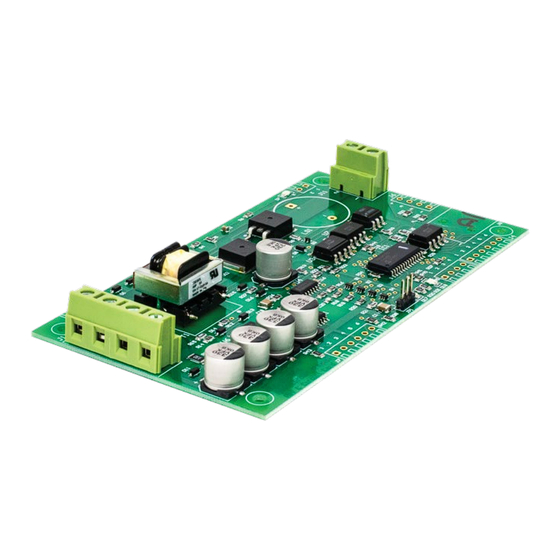
The PSXX-1,2,3 Series
DCC Circuit Breaker
Intelligent, Solid State
Block Detection and Network Feed Back
Manual Rev A [01.22, Software Rev F [07.22]
will work correctly for most layouts.
so you can physically separate and
1
Advertisement

Related Manuals for DCC Specialties PS 1 Series

Summary of Contents for DCC Specialties PS 1 Series
- Page 1 DCC Circuit Breaker Intelligent, Solid State Block Detection and Network Feed Back * info@tonystrains.com Manual Rev A [01.22, Software Rev F [07.22] *Designed by Larry Maier *Developed by DCC Specialties *US Patent 7,810,435 For DCC Use Only New! Advanced Circuit Design New!
- Page 2 PSXX Manual Rev: A Software Rev: F ● Manual or Automatic Reset: Automatic reset: Breaker tries to reset every 2 seconds. Manual reset: Once the breaker trips, it remains off, ensuring complete isolation of the faulty block. The breaker is reset either by a switch or by a DCC command. ●...
-
Page 3: Quick Start
PSXX Manual Rev: A Software Rev: F Instruction Manual Contents A. Quick Start B. User Guidelines C. How to Determine Power Districts D. PSXX-1, 2, & 3 Wiring Terminal Wiring Descriptions Terminal Functions G. PSXX Accessory Addresses H. Programming CV’s & Values CV Settings Special Programming Instructions DCC System Sequential Programming Instructions... - Page 4 PSXX Manual Rev: A Software Rev: F e. Remove the wire from J2. f. Verify D7 and D12 return to ON and D17 turns OFF. Programming CV’s & Values: Optional/Not Required! The easiest way to program PSXX circuit breakers is at your work bench. Programming CV values is done using the Programming On Main [POM] function.
- Page 5 PSXX Manual Rev: A Software Rev: F If you are using both PSXX circuit breakers and PSX-AR auto reversers on a layout make sure the PSX-AR J1 input is taking power from the J2 DCC track output of the PSXX When PSXX are used with PSX-AR, the PSX-AR trip rate must be equal to or less than the trip rate of the PSXX.
- Page 6 PSXX Manual Rev: A Software Rev: F If the D17 LED near the JP1 Programming Jumper is on solid, you may have a short between the two wires from the J2 Output or in the track section. 1. Test the PSXX installation prior to running a train: a.
- Page 7 PSXX Manual Rev: A Software Rev: F district. If you have a single booster for a power district, you still want a PSXX-1 protecting that district. The reason is that the protective circuitry in the booster is designed to protect the booster, NOT your $1000 fully lit, full sound, decoder equipped, fully detailed scale model.
- Page 8 PSXX Manual Rev: A Software Rev: F Based on our experience, a typical HO scale 5 Amp system can support up to 10 operators using a 12-14 AWG bus and 20 AWG feeders. Many users overestimate the amount of Booster power needed. Try using the PSXX Series first. If your DCC Booster overloads from excess current draw, you need to add an extra DCC Booster to support the concentration of trains in this location.
- Page 9 PSXX Manual Rev: A Software Rev: F times every foot. You can make your own twisted pair wire by placing two ends of the wire in a drill bit, chuck the drill tight, and then turn on while you or something else holds the other end ***PSXX LED Outputs do not require resistors*** E.
-
Page 10: Terminal Functions
PSXX Manual Rev: A Software Rev: F PSXX LED Outputs do not require resistors J7 Auto/Manual Reset & Powering LEDs ● J7-1 +5V Output for powering external LEDs, etc. in conjunction with Block Occupied or Block Shorted outputs. Maximum load should be less than 25mA. ●... - Page 11 PSXX Manual Rev: A Software Rev: F – DCC track power output terminal from the PSXX circuit breaker to the track. – Programming & Operation jumper. Normal operating configuration is when the jumper is in the JP1-2 to JP1-3 position. Place the jumper in the JP1-1 to JP1-2 position to enter programming mode.
- Page 12 PSXX Manual Rev: A Software Rev: F J7-5 & J7-6 Output TBD Used to program software updates. Do not make any connections J10-1 [+] and J10-2 [-] output is on any time that D12 (GREEN) is on. This output should ONLY be connected to an isolated LED.
- Page 13 PSXX Manual Rev: A Software Rev: F G.1 Setting the Three Accessory Addresses: 1. Turn off power to the PSXX 2. Place the JP1 programming jumper on pins JP1-1 & JP1-2 3. Connect the DCC track power output of your DCC system to pins J1-1 and J1-2. 4.
- Page 14 PSXX Manual Rev: A Software Rev: F G.2 Using Accessory Addresses: The first PSXX accessory address [Default address 2042, 997 for Digitrax] lets you use DCC Accessory Commands to turn the PSXX DCC output on and off. The second PSXX accessory address [Default address 2043, 998 for Digitrax] is used to arm the photocell circuit.
- Page 15 CV49=10, [10.0 amps] without the addition of heat sinks to the output transistors may overheat or damage the PSXX. Heat sinks are available from DCC Specialties. PSXX’s can also be ordered with heat sinks installed by DCC Specialties.
- Page 16 PSXX Manual Rev: A Software Rev: F Low Current System Trip Current Settings: For the Digitrax Zephyr [DCS50, DCS51, DCS52], setting values of CV49=01, ● 02, & 03 is OK. ● The NCE Power Cab should use the default value of CV49=02. ●...
- Page 17 PSXX Manual Rev: A Software Rev: F CV55 Block Current Trip Hysteresis ● Default = 4. ● The Block Occupied output will turn ON when the detected current is more than the sum of CV54, CV55 and CV56. ● In general, this value should not be adjusted unless the Block Occupied output is chattering on and off.
-
Page 18: All Systems
PSXX Manual Rev: A Software Rev: F If a photocell is connected, it will always be calibrated and disarmed regardless of the value in CV50 ● CV66=2 The PSXX output will assume the same state it was in when the connected booster was last turned off. - Page 19 PSXX Manual Rev: A Software Rev: F Release the control key Once you see the PSXX’s D10 LED flash indicating an address has been stored. If you see multiple flashes, you have stored the same address more than once. Since the PSXX will flash D10 each time you send it an accessory address, you can easily get a feel for the timing involved.
- Page 20 PSXX Manual Rev: A Software Rev: F K. DCC System Sequential Programming Instructions for Setting Address and Programming CV’s For all systems, whenever you enter an address or CV value, you should see D6 flash. This indicates the PSXX has received the information, stored it, and verified the stored data matches the data you sent. Digitrax Using the DT400/402/500 Setting PSXX Addresses: Disconnect PSXX from DCC power...
- Page 21 PSXX Manual Rev: A Software Rev: F For all systems, whenever you enter an address or CV value, you should see D6 flash. This indicates the PSXX has received the information, stored it, and verified the stored data matches the data you sent. Lenz Setting PSXX Addresses: Using the LH100 Turn DCC power off.
- Page 22 PSXX Manual Rev: A Software Rev: F For all systems, whenever you enter an address or CV value, you should see D6 flash. This indicates the PSXX has received the information, stored it, and verified the stored data match the data you sent. NCE Setting PSXX Addresses: Using Pro Cab or Power Cab Turn DCC Power off.
- Page 23 PSXX Manual Rev: A Software Rev: F For all systems, whenever you enter an address or CV value, you should see D6 flash. This indicates the PSXX has received the information, stored it, and verified the stored data matches the data you sent. MRC Setting PSXX Addresses: Using the Prodigy Advance Cab Turn DCC Power off.
Need help?
Do you have a question about the PS 1 Series and is the answer not in the manual?
Questions and answers