Table of Contents
Advertisement
Quick Links
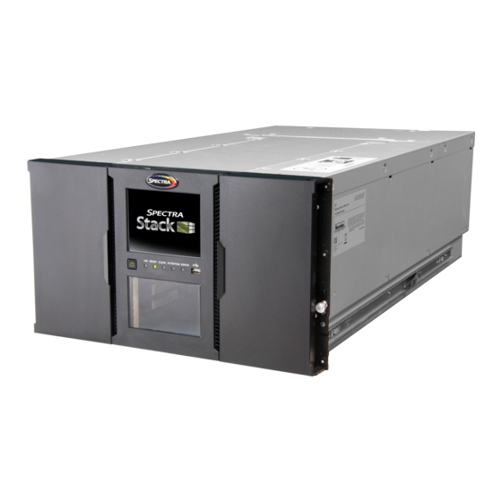
Spectra Stack Tape Library Overview
All Spectra Stack library installations begin with the 6U controller module,
with capacity for 80 tape cartridges and up to six half-height LTO tape drives,
up to three full-height LTO tape drives, or a combination of half-height and
full-height drives.
The Spectra Stack library is expandable, allowing a user to grow the tape
storage capacity as data requirements increase. As data storage needs grow,
the Spectra Stack library can also grow by adding one or more 6U expansion
module(s). Each expansion module supports an additional 80 tape cartridges
and an additional six half-height LTO tape drives or three full-height LTO
tape drives.
Up to six expansion modules can
be added to a controller module,
bringing the total library capacity to
560 tape cartridges and 42 half-
height drives, 21 full-height drives or
a combination of half- and full-height
drives in a single 19-inch NEMA rack.
Precautions
Each Spectra Stack library module weighs approximately 88 lb. (40 kg)
without drives or tape cartridges installed, and approximately 144 lb.
(70 kg) with six tape drives and 80 tape cartridges installed.
WARNING
Before moving or installing the library, observe local health and safety
requirements and obtain adequate assistance to lift and stabilize the
modules during installation or removal.
When installing or removing a library module from a rack:
•
Extend the rack leveling jacks to the floor.
•
Ensure that the full weight of the rack rests on the leveling jacks.
•
Extend only one rack component at a time.
•
Install stabilizing feet on the rack (recommended).
Unpack Library Components
1)
Clear a work surface near the targeted rack where you plan to install the library.
2)
Inspect the shipping container for damage. If you notice any damage, contact
Spectra Logic Technical Support (see page 4 for contact information).
3)
Cut and remove the bands on the outside of the container.
4)
Lift up the outer cardboard box. It is not secured to the pallet and lifts off easily.
5)
Remove the inner cardboard sleeve surrounding the module.
6)
Remove the rack rails and accessory kit.
7)
Remove the foam pieces off of the top of the module.
8)
With assistance, lift the module out of the bottom foam nest.
9)
Remove the wrapping from the module and then place the module on a sturdy
work surface.
10)
Save the packaging materials for future use.
Install Rack Rails
Use the instructions in this section to install the required rack hardware before
installing a library module. Rack hardware is included in the accessory box shipped
with each module.
The included rack-mounting hardware is only compatible with square hole racks.
IMPORTANT
An adaptor kit is available for round hole racks. Some threaded round hole racks
are not supported. The distance between the rack front and rear posts must be
between 26.6 inches and 30.8 inches. Add an additional 1.5 inches when using
adaptors. See the
Spectra Stack Library User Guide
1)
Locate the position where you want to install the Control Module. The rail position
corresponds to the lowest 1U of the module chassis.
2)
If your library includes one or more Expansion Modules, locate the rail position for
each additional module at 6U spacing intervals. Otherwise, continue to Step 3.
3)
Position each rail according to the left-right front-rear orientation information
stamped on the rail.
4)
From the front of the rack, position a rack rail inside the rack and insert the rear rail
hangers into the holes of the rear vertical support of the rack.
5)
Lower the front of the rail until the rail is approximately level.
6)
Extend the front of the rail and insert the hangers through the holes in the vertical
support of the rack (1) until the retention spring snaps into place.
7)
Install a clip nut above the mounting bracket on both of the front vertical supports
of the rack. Position the clip two holes above the top of the mounting bracket (2) at
the front of the rail and push it through the hole in the vertical supports.
8)
Repeat for each additional rack rail.
Prepare Library Modules
The Control Module has a removable cover at the top and bottom of the
library chassis. If your library configuration includes one or more Expansion
Modules, you must transfer one or both covers from the Control Module
to the Expansion Module. If your library configuration does not include an
Expansion Module, skip to Install & Align Library Modules.
Use the instructions in this section to move a cover from the Control
Module to an Expansion Module. The covers are identical and the
procedure to move them is the same for both the top and bottom cover.
•
If you are installing Expansion Modules below the Control Module,
move the bottom cover from the Control Module to the Expansion
Module that you plan to install as the bottom module of the library.
•
If you are installing Expansion Modules above the Control Module,
move the top cover from the Control Module to the Expansion Module
that you plan to install as the top module of the library.
If you plan to remove the bottom cover, you must first remove the
WARNING
top cover and confirm that the shipping lock is in place. Use the
sticker on the top of the robot to lock the robot if needed.
1)
Remove a cover from the Control Module.
a)
Insert a small screwdriver into the hole (1) to retract the spring lock.
b)
Slide the cover toward the front of the Control Module (2) until
it contacts the screwdriver. Remove the screwdriver and continue
for more information.
sliding the cover until all the tabs are released.
c)
Lift the cover off the module (3).
d)
If necessary, repeat to remove the other cover.
2)
Install a cover on an Expansion Module.
a)
Align all tabs on the cover with the slots on the module, gently push
it down, and then slide the cover towards the back of the module
until the spring lock engages.
b)
If necessary, repeat to install the other cover.
Page 1
Advertisement
Table of Contents

Subscribe to Our Youtube Channel
Related Manuals for Spectra Stack


Summary of Contents for Spectra Stack
- Page 1 The included rack-mounting hardware is only compatible with square hole racks. IMPORTANT the Spectra Stack library can also grow by adding one or more 6U expansion Insert a small screwdriver into the hole (1) to retract the spring lock. An adaptor kit is available for round hole racks. Some threaded round hole racks module(s).
- Page 2 If none of the three pre-entered address ranges is suitable for use in your the library. instructions below. network, contact Spectra Logic Technical Support. CAUTION If you encounter resistance, do not force the drive into the drive bay. Click Set and Proceed. The library reboots and displays the Login screen.
- Page 3 Click Next. The Timezone Selection screen displays. Initial Confi guration Wizard If you plan to use Encryption Standard with your Stack library, you must When the library initializes for the first time, the Initial Wizard displays on configure the encryption password before you can configure a partition to the OCP.
- Page 4 Click Next. The Finish Configuration screen displays with details for the partition(s) IMPORTANT You must create at least one partition before you can use your Stack library All library operations stop when a magazine is open. configured using the wizard.
Need help?
Do you have a question about the Stack and is the answer not in the manual?
Questions and answers