Advertisement
Quick Links
TRANSLATION OF THE ORIGINAL USER MANUAL
Manufacturer / distributor:
VacuumChambers.eu
drControl Dawid Roszczenko
Jodłowa 3A/34
16-001 Ignatki-Osiedle
Poland
E-mail: shop@vacuumchambers.eu; Telephone: +48535312207
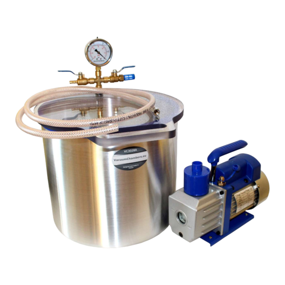
All photos used in this manual are illustrative photos. The appearance and quantity of the elements supplied to the
customer and their mutual location may vary depending on the ordered vacuum set.
This user manual is based on current knowledge and experience. The manufacturer reserves the right to change the content
of this manual without informing the consumer.
ENVIRONMENTAL INFORMATION:
Do not dispose of that product as unsorted municipal waste.
Used equipment should be sent to an electro-waste collection point.
Nature friendly company.
SYMBOLS USED IN THE MANUAL:
Danger - A hazard that can cause injury or damage.
Hot surfaces. Risk of burns.
Read the user manual of the device.
Wear eye protection.
Wear protective gloves.
Wear protective clothing.
2
Advertisement

Related Manuals for VacuumChambers VP115


Summary of Contents for VacuumChambers VP115
- Page 1 Hot surfaces. Risk of burns. Read the user manual of the device. Wear eye protection. Wear protective gloves. TRANSLATION OF THE ORIGINAL USER MANUAL Wear protective clothing. Manufacturer / distributor: VacuumChambers.eu drControl Dawid Roszczenko Jodłowa 3A/34 16-001 Ignatki-Osiedle Poland E-mail: shop@vacuumchambers.eu; Telephone: +48535312207...
-
Page 2: Table Of Contents
READ THIS USER MANUAL BEFORE USE. Keep the user manual for possible future use, as it may always be necessary to remind the information contained therein, and it must be provided with the device in the case of resale or user change. ... -
Page 3: Air Manifold Assembly
The two ball valves allow for adjusting the degassing process, and the mounted vacuum gauge indicates the current vacuum in The device should be operated by trained technicians, mentally and physically able to operate the the chamber. The chamber is equipped with an inlet air filter, which effectively prevents dirt from getting into a degassing vacuum set and its components. -
Page 4: Preparation Of The Vacuum Pump
3) Remove the green plug of the rubber plug on the vacuum gauge. It is recommended to connect the vacuum set only with parts and products supplied by VacuumChambers.eu. Photo 6: Air manifold correctly installed. If the customer connects the vacuum set or its parts with elements or devices from other manufacturers, the customer is solely responsible for the appropriate selection of these elements, their compatibility and the Photo 6 shows a correctly mounted air manifold on the tank wall. -
Page 5: Fitting Muffler
Depending on the selected model or on the customer's order, the vacuum set can be equipped with: a fitting muffler, stirrer mechanism, vacuum trap or vacuum feedthrough with a pouring hose and mechanical flow controller. A. Fitting muffler. stamp Photo 11: Mechanical flow controller. The spare end of the hose should be placed in the vacuum feedthrough (Photo 10). -
Page 6: Vacuum Cold Trap
1. Lid. 2. Clamps. 3. Legs. 4. Castors with brake. 5. Stainless steel drain valve 1 ¼ inches. Picture 1: Correct installation of the castor to the tank leg. D. Vacuum trap. The vacuum trap (Photo 15) is a vacuum chamber with a modified configuration. It is used in the infusion process as a protection for a vacuum pump. - Page 7 1. Vacuum pump connecting valve. 2. Unsealing valve. 3. Inner tank lid with a gasket. 4. Inner tank flange. 5. Outer tank. 6. Vacuum chamber connecting valve. Photo 18: Vacuum cold trap with dry ice inside. Photo 16: Vacuum cold trap. The deposition takes place inside the outer tank.
- Page 8 When operating vacuum pumps that do not come from the VacuumChambers.eu offer, please refer to the operating The chamber must not be used if the lid is shifted to the side, as shown in photo 20 on the right. If the lid is in the wrong instructions supplied with the pump by the manufacturer.
- Page 9 occurrence of its strong adherence to the lid. It is recommended to protect the new gasket surface, for example by technical manufacturer. The pump is worn or Contact the supplier for additional information or to perform damaged. a warranty or post-warranty repair. talc.
-
Page 10: Tank Gasket Replacement
VacuumChambers.eu is not liable for damages, nor does it cover them under the warranty, for any kind of losses resulting from the breakdown of this product. In the case of a claim, VacuumChambers.eu's sole responsibility is to accept a return or The new gasket should be placed on the tank in place of the old one. - Page 11 A. EC declaration on conformity – rotary oil vacuum pumps.
Need help?
Do you have a question about the VP115 and is the answer not in the manual?
Questions and answers