Advertisement
- 1 WARNING
- 2 Introduction
- 3 General List
- 4 Frame Assembly Pt. 1
- 5 Frame Assembly Pt. 2
- 6 Frame Assembly Pt. 3
- 7 Frame Assembly Pt. 4
- 8 Cable Connection
- 9 Screen Information
- 10 Loading Filament
- 11 AUX Leveling
- 12 Auto Leveling
- 13 Software Installation
- 14 Preparing to Print
- 15 Circuit Wiring
- 16 Videos
- 17 Documents / Resources
- This guide book is for standard Ender-5 Plus only.
- Please plug the power cord into a three-hole power jack.
- Detailed instructions are available in the TF card.
WARNING

- Do not use the printer any way other than described herein in order to avoid personal injury or property damage.
- Do not place the printer near any heat source or flammable or explosive objects. We suggest placing it in a well-ventilated, low-dust environment.
- Please place your printer under a stable environment in order to achieve hight print quality.
- Before using experimental or exotic filaments, we suggest using standard filaments such as ABS or PLA to calibrate and test the machine.
- Do not use any other power cable except the one supplied. For your safety, you must use a grounded three-prong power outlet.
- Do not touch the nozzle or printing surface during operation as they may be hot. Keep hands away from machine while in use to avoid burns or other personal injuries.
- Do not wear gloves or loose clothing when operating the printer. Such cloths may become tangled in the printers moving parts leading to printer damage, burns, or personal injuries.
- When cleaning debris from the printer hot end, please use the provided tools. Do not touch the nozzle when heated. This maybe cause personal injury.
- Clean the printer frequently. Always turn the power off when cleaning, and wipe with a dry cloth to remove dust, adhered printing plastics or any other material off the frame, guide rails, or wheels. Use glass cleaner or isopropyl alcohol to clean the print surface before every print for consistent results.
- Children under 10 years of age should not use the printer without supervision.
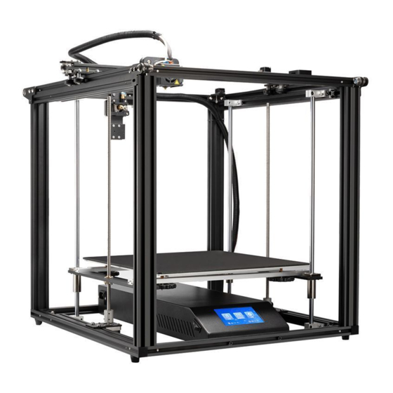
Introduction

- BL Touch
- Broken filament detecting device
- Hot Bed
- Main control box
- Power switch
- Touch screen
- Leveling nut
- Hot end
- X-axis limit switch
- X-axis motor
- TF card& USB
- Z-axis motor
- Antivibration feet
- Filament Holder
- Y-axis motor
- Y-axis limit switch
General List

 Tool List
| No. | Image | Name | Qty |
| 1 |  | Wrench & Screw driver | 1 set |
| 2 |  | TF Card & Reader | 1 set |
| 3 |  | Spatula | 1 |
| 4 |  | Pliers | 1 |
| 5 |  | 0.4 mm Nozzle Cleaner | 1 |
| 6 |  | Power Cable | 1 |
| 7 |  | Filament (200) g | 1 |
| 8 |  | Spare Parts | 1 set |
| 9 |  | USB | 1 |
Frame Assembly Pt. 1

Note: Please note that the hole at the top of piece facing left and right, in relation to the front of the printer.
Step 1. Keep the front of the Bottom Frame facing you.
Step 2. Take one of the Aluminum frame pieces and place it in the corner of the bottom frame, on top of the frame, and lined up with the corner. Notice the hole at the top of piece facing left and right, in relation to the front of the printer. Use 2 M5x25 screws and washers to secure part to the bottom frame.
Step 3. Install the remaining 2 aluminum profile in the same way as Step 3.
Frame Assembly Pt. 2

Note:
- Tighten the four screws on the top, then tight the side screws.
- Facing your top-side Y-axis passive block, you can adjust it to adjust the timing belt tightness.
Step 1. Make sure the front of the bottom frame is facing you.
Step 2.
- Place the Top frame on top of all four aluminum frames.
- Line up the pre-drilled screw holes on tops of aluminum frame with the holes on top of Top frame and tighten in place with an M5x25 screw and washer at each corner.
- After 4 screws on top are tightened, use 4 M5x25 screws and washers to fasten corner brackets in each corner of Top frames, into corresponding holes on outside edge of aluminum frame
Frame Assembly Pt. 3

Step 1. Make sure the front of the bottom frame is facing you.
Step 2. Place double Z-axis frame inside of previously assembled frame. The double Z-axis frame is mounted on the left and right 2040 aluminum profiles of the top frame and must be aligned with the aluminum profile. Making sure the motor is on the bottom, attach the frame to the lower and upper assembly with a M5x30 screw and washer at each corner. The upper and lower assembly extrusions will have corresponding pre-drilled holes for these screws.
Step 3. After the installation of the double Z-axis frame is completed, please check if your Y-axis can move smoothly. If the movement is hindered and the aluminum profile is rubbed, please adjust the eccentric nut and reassemble your Z-axis frame.
Frame Assembly Pt. 4

Step 1. Make sure the front of the base(b) is facing you. Place the hot bed on the support plate of the double Z-axis frame and align with the profile holes on it.
Step 2. Using 4 M4x10 screws, connect the hot bed to the support plate on the Z-axis frame. Make sure the hot bed is flat and all six screws are securely fastened.
Step 3. Subsequently, pass the M5x8 socket head cap screw through the threaded hole on the of the metal plate filament bracket, then pass the M5 T-nut and gently turn the M5 T-nut. Do not tighten. Rotate the M5 T-nut that has been installed on the metal plate filament bracket into a position parallel to the groove of the aluminum profile, and insert it into the aluminum profile. The M5 T-nut below the metal plate filament bracket is parallel to the groove of the 2040 aluminum profile and is inserted into it. The upper M5 T-nut on the metal plate filament bracket is parallel to the 2040 aluminum profile and inlaid, then tighten the screw with an Allen key and tighten the M5 T-nut to a position perpendicular to the groove of the aluminum profile.
Cable Connection

Screen Information

| Screen Information | |||||
| Main Menu | Sub Menu | Explanation | |||
| SD card | Selected file | Stop | |||
| Pause / Continue | |||||
| Adjust | Print speed | ||||
| Nozzle temp | |||||
| Hot-bed temp | |||||
| Z offset | |||||
| Fan | |||||
| Fan(off\on) | |||||
| Temp | Automatic | PLA\ABS(185°\220°) | |||
| Manual | Nozzle preheat | ||||
| Hot-bed preheat | |||||
| Cooling | Yes\No | ||||
| Fan | (Off\On) | ||||
| Setting | Leveling | Z-axis: Z home, +0.1mm, -0.1mm | |||
| AUX leveling | Please click numbers to assist leveling(①~⑤) | ||||
| Auto leveling | Auto leveling, please wait... | ||||
| Check level(Measurement parameters) | |||||
| Refuel | Withdraw | ||||
| Feed | |||||
| Moving | X-axis | Y-axis | Z-axis | Z home | |
| Disable motor | Yes\No | ||||
| Language | English\Chinese | ||||
| Printer info | Machine type, Firmware version, Printing size, website | ||||
Loading Filament
- Preheat

- Feeding

Press and hold the extruder lever and insert the 1.75mm filament through the filament detector and through the extruder motor. Continue feeding until you see filament extrude from the nozzle.


Tip: How to replace the Filament?
- Cutting filament near the Extruder and slowly feed new filament until they are fed into the new filament.
- Preheating the nozzle and withdraw the filament quickly and feed the new filament.
AUX Leveling

- Slightly tighten the four leveling nuts at the bottom of the platform before initial leveling.
- Select "Settings" → "Level mode" → "AUX leveling", click on the number ②.
![]()
- Adjust the platform height by turning the knob underneath. Use apiece of A4 paper (standard printer paper) to assist with the adjustment, making sure that the nozzle lightly presses on the paper.
- Complete the adjustment on all 4 corners.
- Click the number ① to test the platform height in the middle.
- Repeat above steps one or two times if necessary.

 |  |  The nozzle is too far away from the platform, so the consumables can not adhere to the platform. The nozzle is too far away from the platform, so the consumables can not adhere to the platform. |
 |  |  Filament are extruded evenly, just sticking on the platform. Filament are extruded evenly, just sticking on the platform. |
 |  |  The nozzle is too close to the platform, and the filament are not extruded enough, even scraping the platform. The nozzle is too close to the platform, and the filament are not extruded enough, even scraping the platform. |
Auto Leveling

- In "Settings" → "Leveling mode"
- 2mm feeler gauge between the nozzle and the hot bed → If the gap is too thin or too large, click "Z+" or "Z-" on the interface to adjust the gap to slightly more than 0.2 mm(the distance between the nozzle and the hot bed should be about 0.2mm). At 0.2 mm the feeler can easily pass through the gap between the nozzle and the printing platform.


*When using the auto level feature, we suggest that adding a raft from the build plate adhesion section in software settings
Software Installation
- Double click to install the software.
![]()
- Double click to open the software.
![]()
- Select language→ Next → Select your machine → Next → Finish.
![]()


Preparing to Print
- Slicing
Insert TF card into computer with Reader.
Open the software→ Load → Select the file → Wait for slicing to finish, and save the Gcode file to TF card. - Printing

Insert the TF card → Select Print from TF → Select the file.


Circuit Wiring


SHENZHEN CREALITY 3D TECHNOLOGY CO.,LTD.
11F & Room 1201,Block 3,JinChengYuan, Tongsheng Community, Da lang, Longhua District, Shenzhen, China, 518109
Official Website: www.creality3d.cn
Tel: +86 755-85234565
E-mail: info@creality3d.cn cs@creality3d.cn

VideosCreality Ender 5 Plus Review Video
Creality Ender 5 Plus - How to Build Video
Documents / ResourcesDownload manual
Here you can download full pdf version of manual, it may contain additional safety instructions, warranty information, FCC rules, etc.
Advertisement


Need help?
Do you have a question about the Ender-5 Plus and is the answer not in the manual?
Questions and answers