Table of Contents
Advertisement
Quick Links
Vortex Flow meters
EV-200.000.
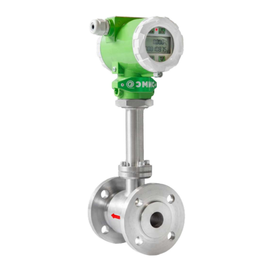
EMIS-VIHR 200 (EV-200)
000.000.00OM
30.09.2019
V4.2.3
For versions EV-200, EV-205,
___________
EV-200-PPD
Operation manual
High accuracy
Accuracy does not
depends on
process
parameters
Working under
high pressure and
temperature
Protection against
water hammer
Simulation test
LED display with
optical buttons
In-built self-check
USB connection
EMIS CJSC
Russia,
Chelyabinsk
Advertisement
Table of Contents

Related Manuals for EMIS EMIS-VIHR 200


Summary of Contents for EMIS EMIS-VIHR 200
- Page 1 Vortex Flow meters EV-200.000. EMIS-VIHR 200 (EV-200) 000.000.00OM 30.09.2019 V4.2.3 For versions EV-200, EV-205, ___________ EV-200-PPD Operation manual High accuracy Accuracy does not depends on process parameters Working under high pressure and temperature Protection against water hammer Simulation test LED display with...
- Page 2 Any use of the trade marks and present manual, partial or full, is prohibited without copyright holder permission. EMIS CJSC has the right to update the product and documents without prior notice if it does not affect product performance. www.emis-kip.ru/ru/prod/ev200...
-
Page 3: Table Of Contents
Appendix A Reference documents Appendix B Connection diagrams Appendix C Installation scheme, dimensions, connection size and weight Appendix D Mounting kit Appendix E EMIS Integrator guide Appendix F Explosion protection scheme Appendix G «Modbus» protocol description Appendix H «HART» protocol description... -
Page 4: Description And Operation
EMIS-VIHR 200 OPERATION MANUAL 1 DESCRIPTION AND OPERATION 1.1. Intended use of the flow meter 1.1.1 Flow transducer is designed for measuring flow and volume of liquids, gases (natural, associated petroleum gas, air, oxygen, etc), saturated and superheated vapour, corrosive mediums under working pressure and temperature and can be applied in different manufacturing spheres and as a part of heat, gas, steam metering systems. - Page 5 EMIS-VIHR 200 OPERATION MANUAL T6) Gb X marking. Flow transducer of explosion proof configuration ЕхC intended for use in explosive environment with explosive mixtures of IIC type, and has explosion protection called "intrinsically safe circuit" and 1Ex ib IIС(T1- T6)Gb X marking.
- Page 6 EMIS-VIHR 200 OPERATION MANUAL Table 1.1.1 - EV-200 and EV-205 symbols Code Item name Full-bore EMIS-VIHR 200 EMIS-VIHR 205 Insertion type Code Explosion protection – No ex-proof ЕхВ 1Ex ib IIB (T1-T6) Gb Х *** ЕхС 1Ex ib IIС (T1-T6) Gb Х *** ЕхiaВ...
- Page 7 EMIS-VIHR 200 OPERATION MANUAL Code Max pressure of medium up to 1.6MPa up to 2.5MPa up to 4.0MPa up to 6.3MPa (for EV-200 only) up to 10MPa (for EV-200 only) up to 16MPa (for EV-200 only) up to 20MPa (for EV-200 only) up to 25MPa (for EV-200 only) Х...
- Page 8 EMIS-VIHR 200 OPERATION MANUAL Code Min medium temperature; – -40 ºС И60 -60 ºС (for E-200 only) Code Industrial versions – standard version for hydrogen sulfide mediums Note: «–» means standard configuration; * - for clamp connection «Т» Dn50 connected to the pipe of Dn65;...
- Page 9 EMIS-VIHR 200 OPERATION MANUAL Max pressure of medium – up to 25 MPa (standard version) up to 20 MPa Display – integrated display with mechanical keyboard integrated display with optical keyboard Configuration standard version version 1 Х special order Output signals –...
- Page 10 EMIS-VIHR 200 OPERATION MANUAL Table 1.2.3 - EV-200 and EV-205 mounting kit symbols Code Item name Full-bore type mounting kit EMIS-VIHR 200 EMIS-VIHR 205 Insertion type mounting kit Code Flow meter size (Pipe DN) 15 mm 100 mm 350 (fro EV-205 only)
- Page 11 EMIS-VIHR 200 OPERATION MANUAL Full-bore EV-200 symbolic specification Code Н Order Mounting kit EMIS-VIHR 200 – Insertion type EV-205 mounting kit symbolic specification Code Н Order Mounting kit EMIS-VIHR 200 – Table 1.2.4 - Mounting kit symbols for PPD version...
-
Page 12: Parameters
EMIS-VIHR 200 OPERATION MANUAL 1.2 Parameters 1.2.1 EV-200 and EV-205 minimum (Qmin) and maximum (Qmax) volume flow rate of water and air measured at 20°С and zero pressure are shown in table 1.3 and 1.4 accordingly. Table 1.3 - EV-200 flow ranges... - Page 13 EMIS-VIHR 200 OPERATION MANUAL Table 1.3: continued Flow volume*, cbm/h Flow meter size Pipeline Temperature code Water (DN), mm connection code for medium Qmin Qmax Qmin Qmax 70, 100 8 (6) 80 (60) 1920 C, F, 1920 250.320 C1, F1...
- Page 14 EMIS-VIHR 200 OPERATION MANUAL Table 1.4 - EV-205 flow ranges Flow volume*, cbm/h Flow meter Pipeline Temperature code Water size (DN), mm connection code for medium Qmin Qmax Qmin Qmax Flow sensor 70, 100, 250 70, 100, 250 2030 1670...
- Page 15 EMIS-VIHR 200 OPERATION MANUAL Table 1.5 - Coefficients for gas flow range calculation under working conditions Min velocity Vmin, m/s Flow meter size Coefficient Coefficient Medium temperature code (DN), mm 70, 100 200,250,320 15 или 25-ФР1 47.4 other 1,5 (1,3*) Note: * Min velocity for extended range is shown in brackets.
- Page 16 EMIS-VIHR 200 OPERATION MANUAL 1.2.5 Working pressure for PPD configuration shall not be less than: 0,3 MPa – for Q ≤ Qmin’; 0,4 MPa – for Qmin’ < Q ≤ 0,5•Qmax’; 0,8 MPa – for Q > 0,5•Qmax’. 1.2.6 Relative accuracy for volume and volume flow rate measured at frequency, pulse and digital signals and current signal for version A1, H1, H2, H3 depending on flow meter accuracy class is shown in Table 1.7.
- Page 17 EMIS-VIHR 200 OPERATION MANUAL 1.2.9 Pulse or digital output signal. An output can work in different modes: frequency, pulse or digital. Output signal can be in two logical states: "closed"/"opened". It is passive output of open collector type. There are two pulse outputs for T version with 2-wire connection type. One of them corresponds to NAMUR standard.
- Page 18 Modbus RTU (Modicon Modbus Protocol Reference Guide P1-MBUS-300 Rev. G) and provides network connection and measured data transfer. ModBUS transfers the following data to Windows PC with installed EMIS-Integrator software (supplied with flow meter upon request and available on our web-sitewww.emis-kip.ru): flow tube diameter, mm;...
- Page 19 EMIS-VIHR 200 OPERATION MANUAL - signal values on current and pulse outputs; - pulse value and length; - flow value corresponding to 4 and 20 mA at the current output and to 1000Hz at the frequency output; - cut-off value corresponding to the specified signal amplitude;...
- Page 20 EMIS-VIHR 200 OPERATION MANUAL Table 1.10 - List of materials Material Pressu Tmea Materia Version Dn, mm Sensor s., °С re, Mpa l code Flow tube Bluff body Sensor gasket* EV-200 C, F, Fluorine ≤ 320 Н 1,6-6,3 AISI 304...
-
Page 21: Explosion Protection
EMIS-VIHR 200 OPERATION MANUAL 1.3 Explosion protection 1.3.1. Ex-proof transmitters Вн have "explosion proof enclosure" under GOST IEC 60079-1-2011, used for explosive mixtures of IIC group, executed as "explosion proof" and marked as "1ExdIIC(T1-T6)X". Electrical parts of the flow meter are enclosed into explosion-proof casing which bears explosion pressure and help to avoid explosion transfer into the flammable environment. - Page 22 EMIS-VIHR 200 OPERATION MANUAL - medium temperature shall not exceed specified value as marked in the ex-proof marking for this specific temperature class; - the LCD display operates at a temperature not lower than minus 20 ºС; - ЕхВ, ЕхС, ЕхiaВ, ЕхiaС power supply shall be provided from intrinsically safe unit with output circuits of "ib"...
-
Page 23: Flow Meter Parts
1.4.2 Mounting kit is supplied upon request. Installation kit depends on transmitter version and shown in Appendix D. Table 1.12 - Standard supply scope Name Number Note Vortex flow meter EMIS-VIHR 200 As ordered Data sheet ЭВ-200.000.000.000.00 PS For EV-200 versions Data sheet ЭВ-205.000.000.000.00 PS For EV-205 versions Operation manual ЭВ-200.000.000.000.00 OM... -
Page 24: Configuration And Operation
EMIS-VIHR 200 OPERATION MANUAL 1.5 Configuration and operation 1.5.1 Structure and Operation Principle Full-bore transmitter (see fig.1.2) consists of flow tube (1) and electronic transmitter unit(2). Flow tube is a hollow cylinder with bluff body installed in cross-sectional area (3). Sensor (4) is installed behind the bluff body. - Page 25 1.5.2 Flow meter size selection Flow meter selection is performed using specially designed calculator "EMIS Selector" based on the data provided by a customer. Please consider the following when choosing the flow meter: 1. Inner diameter of flow meter (nominal diameter) shall be selected depending on flow velocity which causes vortices shedding of necessary power.
-
Page 26: Marks And Seals
EMIS-VIHR 200 OPERATION MANUAL 1.6 Marks and seals 1.6.1 Marking Marking plate placed on transducer contains the following signs and notes according to GOST 12971 Instrument approval mark as per PR 50.2.104. serial number and date of manufacture; flow meter code;... -
Page 27: Application
- fill flow tube with measured medium. - use bandpass filters. See help tab in EMIS-Integrator. If above mentioned measures do not help, try to adjust low flow cut-off value via EMIS-Integrator. Set low flow cut-off value VS as: VS = 2∙Aв... - Page 28 2.1.7 Full-bore flow meters can measure liquids with gas inclusions up to 15% by volume with ±6,5% accuracy. 2.1.8 Flow meter is supplied with compensated temperature error. Manufacturer adjusts a device according to the temperature range specified in customer order sheet using EMIS-Integrator. Temperature can be re-adjusted by the customer. www.emis-kip.ru/ru/prod/ev200...
- Page 29 EMIS-VIHR 200 OPERATION MANUAL Temperature error is compensated automatically after connecting thermal sensor and installing its software. 2.1.9 Pulse value m on pulse output (pulse and frequency modes) and relevant volume flow rate Q’max at maximum output signal frequency for each flow meter size depending on medium are shown in table 2.2. (by default).
- Page 30 When using a flow meter to measure the flow rate of saturated vapour, the degree of steam dryness should be at least 0.8. 2.1.13 Insertion type flow meter measures flow velocity. To reach required accuracy, measure actual inner diameter of a pipeline and input this value in the device memory via EMIS-Integrator. www.emis-kip.ru/ru/prod/ev200...
- Page 31 EMIS-VIHR 200 OPERATION MANUAL Measuring section shall be selected in the straight run not closer than 5 Dn before the end of this straight section. Square of measuring section shall be calculated as arithmetic average of four diameters equally spaced in cross section.
-
Page 32: Mounting Requirements
EMIS-VIHR 200 OPERATION MANUAL 2.2 Mounting requirements 2.2.1 General rules of mounting Mounting (dismantling), electric connection, adjustment, operation shall be performed by duly authorized and electrically trained personnel who carefully read present manual. Please follow mandatory rules when proceeding flow meter installation: provide free access to the flow meter;... - Page 33 EMIS-VIHR 200 OPERATION MANUAL 2.2 Mounting requirements To provide declared accuracy follow installation requirements below: 1) Pipe inner diameter 2xDN before the flow meter shall comply with the formula below: 0,98Di ≤ Dp ≤ 1,05Di, (2.4) where Di - inner diameter of the flow tube, mm. (see size C in fig.C.3 - C.12).
- Page 34 EMIS-VIHR 200 OPERATION MANUAL Figure 2.5 - Installation scheme for Dn65 and less using straight sections mounting kit We recommend to use specially designed straight sections and flanges for mounting flow meters of Dn65 and less that can be supplied upon request. Straight sections and flanges in the kit have specially treated surfaces to provide precise alignment while welding.
- Page 35 EMIS-VIHR 200 OPERATION MANUAL Table 2.8 - Flow conditioner size Nominal diameter, mm D, mm d(min), mm S, mm 1.16 11.5 15.4 19.3 21.1 Note: Number of holes - 32 Flow conditioner holes size and location comply with Zanker plate configuration under GOST 8.586.2.
- Page 36 EMIS-VIHR 200 OPERATION MANUAL 2.2.4 Mounting Mounting shall be performed as follows: 1) Prepare straight run as an assembly with flanges (see Appendix F) and coupling according to the drawings in Appendix C. Figure 2.10 - Installation of coupling with straight sections 2) cut off pipeline section of Linst length (figure 2.10).
- Page 37 EMIS-VIHR 200 OPERATION MANUAL PPD type flow meters shall be installed without gaskets. Tightening force for each stud shall be not less than: - 40 kN for DN 50mm pipeline; - 82 kN for DN 80mm pipeline; - 107 kN for DN 100mm pipeline - 160 kN for DN 150mm pipeline 2.2.5 Flow meter rotation...
- Page 38 Sensor detects flow velocity and to calculate flow rate you should measure inner diameter of the pipe and input this value into device memory using EMIS-Integrator. To ensure accuracy, provide straight run as required (see table 2.7).
- Page 39 EMIS-VIHR 200 OPERATION MANUAL Attention! To ensure tightness when installing a insertion type flow meter and adjusting the immersion depth of the flow sensor, please follow the installation recommendations given in Appendix L. When measuring flow velocity in 0,242R point, provide depth of insertion of±0,013R.
-
Page 40: Operation
RS-485 / USB allow to adjust and read the flow meter using PC, integrate several flow meters into one network or connect to existing networks via RS-485 and Modbus RTU. EMIS-Integrator is designed to read and adjust flow meter via PC. Software functions and operation are specified in software QA. - Page 41 2.3.4.4 If process parameters are different from above, select type of installed temperature and pressure gauges via EMIS-Integrator, input medium temperature and pressure for cases if sensor is not installed or broken, and adjust other parameters. We recommend to indicate process parameters in order sheet so that we can adjust the flow meter for you.
- Page 42 Wrong port selected for digital output Go to System and identify port number which the flow connection. meter is connected to, select respective port in EMIS- Integrator. Electronics failure due to external Replace the set of electronic boards. Use EMIS- disturbance.
- Page 43 (zero level). Flow meter will indicate current parameters without restart but buttons control may continue unstable. 2.3.6.6 Flow meter repair shall be performed using spare parts and accessories produced by EMIS. The manufacturer is not responsible for any repair fullfilled using other manufacturer's spare parts and accessories.
-
Page 44: Maintenance
EMIS-VIHR 200 OPERATION MANUAL 3 MAINTENANCE Maintenance of ex-proof type flow meters shall be performed according to GOST 31610.17-2012 (IEC 60079-17:2002). The flow meter put into operation does not require special maintenance other than periodic inspection to verify operation conditions. -
Page 45: List Of Possible Failures
EMIS-VIHR 200 OPERATION MANUAL 5 LIST OF POSSIBLE FAILURES List of possible failures (including critical) seal failure of the body caused by destruction; seal failure of the gaskets; loss of tightness in plug connections; Non-compliance with the requirements of table 1.7. -
Page 46: Storage
EMIS-VIHR 200 OPERATION MANUAL 6 STORAGE Keep flow meter indoor on the shelve after unpacking. Storage conditions after unpacking shall comply with GOST 15150 under ambient temperature of -50 to +40°С and relative humidity of 95% non-condensing at 25°С. Do stack flow meter on top of each other. -
Page 47: Appendix A Reference Documents
EMIS-VIHR 200 OPERATION MANUAL Appendix A (informative) Reference documents Table 1 Document code Name Item No Instructions for Installation of electrical equipment, power and ВСН 332-74 2.2.7 lighting systems in explosive environment Tubular inside micrometers. Technical conditions 2.1.14 GOST 10-88 Calipers. - Page 48 EMIS-VIHR 200 OPERATION MANUAL Document code Name Item No Machines, instruments and other industrial products Modifications for different climatic regions. Categories, operating, storage and GOST 15150-69 1.1.9; 5; 6 transportation conditions as to environment climatic aspects influence. Welded connections of pipes Main types, structural elements and...
-
Page 49: Appendix B Connection Diagrams
EMIS-VIHR 200 OPERATION MANUAL Appendix B (normative) Connection disgrams 1. PS1 - power supply unit 12 to 27 V DC 2. PS2 - DC power supply unit see 1.2.10 3. PS3 - power supply unit 5 to 27 V DC 4. - Page 50 EMIS-VIHR 200 OPERATION MANUAL Figure B.1 - Order of terminal clamps for special version transmitters. Comments to power supply units: - Power supply PS1 is used for general power supply of flow meter (display, digital output ModBUS. etc.) and is obligatory unit. Power supply 12 to 27 V - Power supply PS2 is used for frequency-pulse output power supply.
- Page 51 EMIS-VIHR 200 OPERATION MANUAL - Power supply PS1 is used for flow meter power supply. - Power supply PS2 is used for frequency-pulse output power supply. - PS2 is not obligatory (if corresponding outputs are not used). - It is not recommended to use PS1 with secondary circuit grounding for flow simulation.
- Page 52 EMIS-VIHR 200 OPERATION MANUAL Appendix B Figure B.5 - Front panel view [X] Ratio of volume flow to [X] 16-bit diagnostic [X] 16-bit diagnostic [X] Ratio of volume flow to [X]Transmitter temp., °/ [X]Transmitter temp., °/ [X]Medium pressure, MPa [X]Medium pressure, MPa...
- Page 53 EMIS-VIHR 200 OPERATION MANUAL Appendix B Fig.B.1 - Display of parameters for SIM and SIO config. Menu Navigation Indication Menu description line buttons Volume flow rate, m3/h Current and total volume flow Total volume, m3 (value in upper line) Total volume flow rate under normal...
-
Page 54: Appendix C Installation Scheme, Dimensions, Connection Size And Weight
EMIS-VIHR 200 OPERATION MANUAL Appendix C (informative) Installation scheme, dimensions, connections sizes and weight Figure C.1 - Installation scheme for flow meters of “wafer” type without flanges Figure C.2 - Installation scheme for flow meters with flanges www.emis-kip.ru/ru/prod/ev200... - Page 55 EMIS-VIHR 200 OPERATION MANUAL Appendix C H, mm Weight, kg Version A, mm L, mm C, mm up to up to 250,320ºC 250,320ºC 100ºC 100ºC 10.0 Figure C.3 - Flangless flow meter size Configuration “C” pressure up to 6,3 MPa...
- Page 56 EMIS-VIHR 200 OPERATION MANUAL Appendix C H, mm Weight, kg Version A, mm B, mm L, mm C, mm up to up to 250,320ºC 250,320ºC 100ºC 100ºC 11.5 11.9 Figure C.4 - Flangless flow meter size Configuration “C1” pressure up to 6,3 MPa...
- Page 57 EMIS-VIHR 200 OPERATION MANUAL Appendix C H, mm L, mm Pressure, Weight Dn, mm Type up to 100ºC 250,320ºC , kg 1,6-4 ̶ ̶ ̶ ̶ 1,6-4 ̶ 1,6-4 1,6-4 ̶ ̶ ̶ 1,6-4 1,6-4 ̶ ̶ ̶ 1,6-4 1,6-4 1,6-2,5 ̶...
- Page 58 EMIS-VIHR 200 OPERATION MANUAL Appendix C H, mm L, mm Pressure, Weight, Dn, mm D, mm A, mm B, mm up to 100ºC 250,320ºC d, mm 1,6-4 ̶ ̶ ̶ 1,6-4 1,6-4 1,6-4 ̶ ̶ ̶ 11.5 1,6-4 1,6-4 ̶...
- Page 59 EMIS-VIHR 200 OPERATION MANUAL Appendix C Pressure, Weight, Dn, mm D, mm Type A, mm B, mm L, mm C, mm H, mm d, mm n, pcs 1,6-4 1,6-4 1,6-4 1,6-4 1,6-4 1,6-2,5 1,6-2,5 1,6-2,5 1,6-2,5 1,6-2,5 Figure C.7 - Dimensions for F configuration, temperature up to +450°С.
- Page 60 EMIS-VIHR 200 OPERATION MANUAL Appendix C Pressure, Dn, mm D, mm A, mm B, mm L, mm C, mm H, mm d, mm n, pcs Weight, kg 1,6-4 1,6-4 1,6-4 1,6-4 1,6-4 1,6-4 1,6-4 1,6-4 1,6-4 1,6-4 Figure C.8 - Dimensions for F1 configuration, temperature up to +450°С.
- Page 61 EMIS-VIHR 200 OPERATION MANUAL Appendix C Weight, Size Version A, mm B, mm C, mm D, mm L, mm H, mm 50/10 50/20 50/25 50/50 50/60 80/20 17.8 80/35 17.5 80/50 17.7 80/150 14.7 100/25 100/50 16.6 100/120 14.4 100/200 13.4...
- Page 62 EMIS-VIHR 200 OPERATION MANUAL Appendix C Weight, Size A, mm B, mm C, mm D, mm L, mm H, mm 50/25 80/25 11.7 80/50 11.2 80/100 100/200 11.4 150/500 16.1 Figure C.10 - Dimensions for PPD configuration of 1 type configuration flow meter...
- Page 63 EMIS-VIHR 200 OPERATION MANUAL Appendix C H, mm Weight, Dn, mm A, mm C, mm D, mm E, mm F, mm L, mm up to 250,320ºC 100ºC Figure C.11 - Dimensions for C configuration 16-25 MPa www.emis-kip.ru/ru/prod/ev200...
- Page 64 EMIS-VIHR 200 OPERATION MANUAL Appendix C H, mm Pressu Weight, Dn, mm F, mm L, mm up to 250, re, MPa 100ºC 320ºC 10-16 10-16 10-16 10-16 10-16 10-16 Figure C.12 - Dimensions for F1 configuration 16-25 MPa www.emis-kip.ru/ru/prod/ev200...
- Page 65 EMIS-VIHR 200 OPERATION MANUAL Appendix C H, mm Weight, Dn, mm , mm D , mm up to 250, 100ºC 320ºC Figure C.13 - Dimensions for T configuration www.emis-kip.ru/ru/prod/ev200...
- Page 66 EMIS-VIHR 200 OPERATION MANUAL Appendix C Weight, Dn, mm 300 – 500 1160 1230 600 – 1100 1460 1530 1200 – 1600 1160 1230 1800 – 2000 1460 1530 8 holes Weldneck size for 1.6 MPa Figure C.14 - Insertion type flow meter size for 1.6 MPa...
- Page 67 EMIS-VIHR 200 OPERATION MANUAL Appendix C 8 holes Weldneck size for 2.5 and 4.0 MPa С С С Weig Weig Weigh ht, kg ht, kg t, kg 1200 1400 1600 1040 1110 1800 1000 2000 Figure C.15 - Insertion type flow meter size for 2.5 and 4.0 MPa...
- Page 68 EMIS-VIHR 200 OPERATION MANUAL Appendix C Size in brackets - for version +200ºС, +250ºС and +320ºС Figure C.16 - Remote flow meter sizes Other dimensions see Fig.C.3...C.13 Figure C.17 - Mounting coupling sizes see Fig.C.3...C.9 www.emis-kip.ru/ru/prod/ev200...
- Page 69 EMIS-VIHR 200 OPERATION MANUAL Appendix C Figure C.18 - Mine version flow meter sizes www.emis-kip.ru/ru/prod/ev200...
-
Page 70: Appendix D Mounting Kit
EMIS-VIHR 200 OPERATION MANUAL Appendix D (informative) Mounting kit Table D.5 Fasteners for EV-200 with connection type “C” pressure up to 6,3 MPa Stud GOST 9066 GOST 9064 1.6–2.5 MPa 4 MPa 6.3 MPa Number 1.6-4 MPa 6.3 MPa Number АМ12х140... - Page 71 EMIS-VIHR 200 OPERATION MANUAL Appendix D Table D.4 Fasteners for converters EV-200 with connection type "F1", "FR1" and the temperature of the measured medium up to + 320 °С GOST 9066 GOST 9064 1.6–2.5 1.6–2.5 4 MPa 6.3 MPa 4 MPa 6.3 MPa...
- Page 72 EMIS-VIHR 200 OPERATION MANUAL Appendix D Fig. D.1.1 Fig. D.1.2 Figure D.1 - Flange size for EV-200 configuration ≤ 6,3 MPa Table D.7 Fasteners for EV-200 with connection type “F1”, pressure ≤ 6,3 and the temperature of the measured medium + 450 °С...
- Page 73 EMIS-VIHR 200 OPERATION MANUAL Appendix D Table D.8 Flange size for EV-200 with connection type "C", “F”, "FR" pressure ≤ 6,3 Dn ≤ 100mm Connec tion to Pressu Temp, Weight, Dn, mm Fig. °С pipelin re, MPa ≤ 2.5 D.1.1 С...
- Page 74 EMIS-VIHR 200 OPERATION MANUAL Appendix D Table D.9 Flange size for EV-200 with connection type "C1,“F1”, "FR1", pressure ≤ 6,3 and the temperature of the measured medium + 320 °С Connection Pressure Weight, Dn, mm Fig. to pipeline , MPa ≤...
- Page 75 EMIS-VIHR 200 OPERATION MANUAL Appendix D Fig. D.2.1 Fig. D.2.2 Fig. D.2.3 Figure D.2 - Flange size for EV-200 "F"configuration pressure ≤ 6,3 MPa, Dn > 100mm Table D.10 Flange size for EV-200 with connection type "F" pressure ≤ 6,3 Dn > 100mm...
- Page 76 EMIS-VIHR 200 OPERATION MANUAL Appendix D Table 1.11 - PPD version fasteners Pcs. GOST GOST Size Config. Flanges Studs* Nuts 9066 9064 50/10, 50/20, 50/25, АМ24х260 АМ24 (S36) 50/50, 50/60 80/20, 80/35, 80/50, АМ30х340 АМ30 (S46) 80/150 100/25, 100/50, 100/120, АМ30х340...
- Page 77 EMIS-VIHR 200 OPERATION MANUAL Appendix D Fig.D12 - Flange size for "C" configuration 10-25 MPa pressure Pcs. GOST Р Pressure, Gasket GOST GOST Size Gasket 53561 9066 9064 Studs* Nuts АМ16х180 * АМ16 (S24) 10, 16 1-1-25-200 АМ24х220 АМ24 (S36) 20, 25 АМ16х180 *...
- Page 78 EMIS-VIHR 200 OPERATION MANUAL Appendix D Fig.D13 - Fasteners for "F1" configuration 10-16 MPa pressure GOST Р 53561 Gasket Pcs. GOST GOST Nuts, Size Gasket 9066 9064 10 MPa 16 MPa Studs* washer АМ12х80 АМ12 (S18) 1-1-15-160 АМ16х100 АМ16 (S24) 1-1-25-200 АМ20х120...
- Page 79 EMIS-VIHR 200 OPERATION MANUAL Appendix D Fig. D.4.4 Fig. D.4.1 Fig. D.4.2 Fig. D.4.5 Fig. D.4.3 Pressure, Weight, Size A, mm B, mm C, mm D, mm E, mm F, mm L, mm d, mm Fig. 10, 16 D.4.1 20, 25 D.4.1...
- Page 80 EMIS-VIHR 200 OPERATION MANUAL Appendix D Fig. D.5.1 Fig. D.5.4 Fig. D.5.2 Fig. D.5.5 Fig. D.5.3 Pressure, Weight Size F, mm L, mm d, mm Fig. count , kg 10-16 D.5.1 10-16 D.5.1 10-16 D.5.1 10-16 D.5.1 D.5.2 10-16 D.5.2 D.5.2...
- Page 81 EMIS-VIHR 200 OPERATION MANUAL Appendix D Table D.14 Fasteners material Mounting kit Version Standard version Upon request* content 12Х18Н10Т, 30ХМА Studs, bolts Galvanized steel 12Х18Н10Т, 30ХМА Nuts, washers Galvanized steel Graflex, Spiral wound Gasket, Paronite ПОН-Б Pressure up to 6.3 MPa Paronite PMB Steel 09Г2С...
-
Page 82: Appendix E Emis Integrator Guide
OPERATION MANUAL Appendix E (informative) EMIS-Integrator guide EMIS-Integrator is designed to read and adjust flow meter via PC. You can download EMIS-Integrator here http://www.emis-kip.ru. For more details see software Help To install the EMIS-Integrator, launch «EMISSoftware_Х_Х_Х.exe», where Х.Х.Х -stands for the software version (3.0.0 and older). -
Page 83: Appendix F Explosion Protection Scheme
EMIS-VIHR 200 OPERATION MANUAL Appendix F (normative) Explosion protection scheme Drawings of explosion protection for Вн type flow meter with four cable inputs www.emis-kip.ru/ru/prod/ev200... - Page 84 EMIS-VIHR 200 OPERATION MANUAL Drawings of explosion protection for Вн type flow meter with two cable inputs. www.emis-kip.ru/ru/prod/ev200...
- Page 85 EMIS-VIHR 200 OPERATION MANUAL Drawings of explosions protection for Вн remote type flow meters. www.emis-kip.ru/ru/prod/ev200...
- Page 86 EMIS-VIHR 200 OPERATION MANUAL Drawings of explosion protection for mining configuration flow meters. www.emis-kip.ru/ru/prod/ev200...
- Page 87 EMIS-VIHR 200 OPERATION MANUAL www.emis-kip.ru/ru/prod/ev200...
- Page 88 EMIS-VIHR 200 OPERATION MANUAL www.emis-kip.ru/ru/prod/ev200...
- Page 89 EMIS-VIHR 200 OPERATION MANUAL www.emis-kip.ru/ru/prod/ev200...
- Page 90 EMIS-VIHR 200 OPERATION MANUAL www.emis-kip.ru/ru/prod/ev200...
-
Page 91: Appendix G "Modbus" Protocol Description
EMIS-VIHR 200 OPERATION MANUAL Appendix G (informative) «Modbus» protocol description Protocol interface have almost the same functions as Modbus RTU (Rev.G). The following functions are supported: Table G.1 - Supported functions Function code Sub-Function code Command (function) (HEX) (HEX) Common commands:... - Page 92 EMIS-VIHR 200 OPERATION MANUAL Appendix G Address Registers quantity Description 36145 Vortex sensor signal selection 37169 Acceleration sensor signal selection 33073 Power spectrum of vortex sensors 34097 Vortex sensor signal selection after all filters 38193 64-bit power spectrum of vibration sensor (acceleration gauge) Power spectrum value can be ranged from 0 to 16383, signal selection values can be ranged from -32768 to 32767.
- Page 93 EMIS-VIHR 200 OPERATION MANUAL Appendix G Function code 43h (password entry). Current access level (register 30046) can be read with "read input registers" function. Request contains: Address Function code 43h Password (digit Int32) in high byte-low byte order (4 bytes in total)
- Page 94 EMIS-VIHR 200 OPERATION MANUAL Appendix G Table G.2- Input registers Variable description format 30001 Diagnostics register. Bit values contain the following: 0 bit- read error (checksum error) bit 1- flow under WC during stated period bit 2- self-diagnostics error or charge amplifier error This is a stuck bit, can be reset after power...
- Page 95 EMIS-VIHR 200 OPERATION MANUAL Variable description format 30044* Current code for analog-to-digital conversion of 4-20 mA signal from pressure gauge 30045 Spectrum dispersion (conditions of cavitation and chaotic vortex shedding) 30046 Current access level. May take the value from 0 (low) to6 (when SW1:1 is switched on)
- Page 96 EMIS-VIHR 200 OPERATION MANUAL Table G.3 - Holding registers Access Variable description format level 40001 Device IP in Modbus network shall be from 1 to 247 as stated in protocol. 40002 RS-485 data communication speed. Encoded as follows: 0 – 4800 bit/s, 1 –...
- Page 97 EMIS-VIHR 200 OPERATION MANUAL *13- mass dosing unit with dose in g stated in 40903 register Normally closed contact Note: after selecting operation mode check bit 10 in diagnostics register. If it is stated as one then maxumum frequency of pulse output exceeds allowed value of 1200 Hz in frequency mode and 500 Hz in pulse mode.
- Page 98 EMIS-VIHR 200 OPERATION MANUAL *7- medium pressure, MPa 8- ratio of volume flow to nominal measuring range 9- letter "E", space and diagnostics register data in hex format. Note- when insertion mode in ON (40014): *3- current volume flow in m3/h, insertion mode...
- Page 99 EMIS-VIHR 200 OPERATION MANUAL Access Variable description format level 40067 * Lower limit of pressure gauge in natural units defined in register 40015 float 40069 * Upper limit of pressure gauge in natural units float 40071 dynamic viscosity in MPa⋅, input manually. Used for Reynolds number calculation if float 40014 register disable viscosity tables.
- Page 100 EMIS-VIHR 200 OPERATION MANUAL Access Variable description format level 40123 Coefficient B for gas filter's quadratic equation- upper cut-off. float 40125 Coefficient A for gas filter's quadratic equation- upper cut-off. float 40127 Lower frequency for gas filter float 40129 Upper frequency for gas filter...
- Page 101 EMIS-VIHR 200 OPERATION MANUAL Access Variable description format level 40711 * Density table based on temperature for 8 code mediums Gas density is analytically float tractable parameter so this address area is not used. 40743 * Density table based on temperature for 9 code mediums Gas density is analytically float tractable parameter so this address area is not used.
- Page 102 EMIS-VIHR 200 OPERATION MANUAL Access Variable description format level 40928 Number of Fast Fourier Transformation points is used for signal frequency calculation. Encoded with two bits as follows: D1 D0 1024 points, 512 points, 256 points, 128 points. Bits D2-D15 are not used.
-
Page 103: Appendix H "Hart" Protocol Description
The protocol description and HART version 7 commands for an electronic converter with a two-wire connection scheme are available for download at http://www.emis-kip.ru. HART verson 6 commands for standard and extended version are shown in the tables H.1 - H.2. - Page 104 EMIS-VIHR 200 OPERATION MANUAL Command No and function Command data Request Read common static Byte 0 block number Byte 0 Block number (“3”) data (block 3): read output (“3”) Byte 1 alarm select code (“0”) data. Byte 2 transfer function code (“0”)
-
Page 105: Appendix I List Of Measuring Instruments Used For Calibration
СТЦ-1 4. Stopwatch Accuracy ± 0,1 sec. ТУ25-07.1353-77 Personal computer with installed Windows 5. Personal computer 95/98/2000, EMIS-Integrator and reserved COM- port. Flow range from 0,03 up to 100m3, УПСЖ 100/ВМ relative error for comparison method not 6. Calibration unit TU 4381-001- exceeds ±0,25 %, for indirect method not... - Page 106 0,02 % + 5dgt Р4831 9 Resistance multiplier Resistance up to 1000Ohm, relative accuracy ± 0,05 10 Personal computer Personal computer Windows 95/98/2000/ХР/Vista/7 with installed EMIS- IBM compatible Integrator and reserved COM or USB port or pine output. С1-117/1 11. Oscilloscope Range not less than 100 kHz ТГ2.044.016ТУ...
-
Page 107: Appendix J Insertion Type Flow Meter Adjustment According To Application Conditions
Insertion type flow meter adjustment according to application conditions Use EMIS-Integrator (at-most-once operation) to adjust insertion type flow meter to use with a specific pipe diameter or recalculate pulse value on pulse output and maximum flow rate corresponding with upper limit of current output signal. - Page 108 EMIS-VIHR 200 OPERATION MANUAL Table J.3 - List of measuring instruments used for pipe diameter measurement Name Technical requirements 1. Metal tape measure Р10Н2К, Length 10m, division 0,5mm GOST 7502-98 2. ultrasonic thickness gauge УТ- Range 3...30mm, relative error 3 % 93П, GOST 25863-83...
-
Page 109: Appendix K In-Process Installation Of 1,6Mpa Insertion Type Flow Meter Without Flow Interruption
EMIS-VIHR 200 OPERATION MANUAL Appendix K (normative) In-process installation of 1,6MPa insertion type flow meter without flow interruption Table K.1 Installation procedure without flow interruption Operation Figure У1 7 ГО С Т 1 6037-80 У1 7 ГО С Т 1 6037-80 1. - Page 110 EMIS-VIHR 200 OPERATION MANUAL 3. Prepare hole drilling device. 4. Put drilling unit on the ball valve, install the gasket between the flanges. Fix the unit with bolts and nuts. See item 2 on the tightening scheme. Open ball valve.
- Page 111 EMIS-VIHR 200 OPERATION MANUAL 5. Bring drill into the open valve close to the pipeline surface. Switch on drilling unit. Drill a hole in the pipeline keeping vertical direction of the cutter. www.emis-kip.ru/ru/prod/ev200...
- Page 112 EMIS-VIHR 200 OPERATION MANUAL 6. Bring up cutter with the cut section of the pipeline. Close ball valve. Switch off driller and put it off from the ball valve. 7. Fix flow meter to the ball valve using bolts and nuts. Place new gasket between ball valve flange and flow meter flange.
- Page 113 EMIS-VIHR 200 OPERATION MANUAL 8. Turn the handle and put the sensor down into the pipe until required depth (until it reached the axis of the pipeline for the pipeline diameter not exceeding 800mm). Calculate A size to ensure appropriate depth of immersion for sensor H as follows: А...
- Page 114 EMIS-VIHR 200 OPERATION MANUAL www.emis-kip.ru EMIS CJSC Sales department Maintenance department 454091 Russian +7 (351) 729-99-12 +7 (351) 729-99-12 Federation, Chelyabinsk (multichannel) add. 741, 744, 756, 763. bld.3, room 308 Lenina Ave +7 (351) 729-99-16 support@emis-kip.ru sales@emis-kip.ru...
Need help?
Do you have a question about the EMIS-VIHR 200 and is the answer not in the manual?
Questions and answers