Table of Contents
Advertisement
Quick Links
Advertisement
Table of Contents

Related Manuals for EMIS MASS 260


Summary of Contents for EMIS MASS 260
- Page 1 EM-260.000.000.000.00 OM CORIOLIS FLOW METER EMIS- MASS 260 12.11.2021 v1.0.9 Operation manual Direct mass flow measurement High accuracy Digital processing of signals No straight run required Applicable for high viscous liquids EMIS Russia, Chelyabinsk...
- Page 2 EM-260) EMIS CJSC has the right to update the product and documents without prior notice if it does not affect product performance. For any information about present Operation Manual or other EMIS equipment please contact your local dealer or EMIS head office.
-
Page 3: Table Of Contents
EMIS-MASS 260 OPERATION MANUAL Contents Description and operation ..........................5 1.1 Application ..............................5 1.2 Structure and Operation Principle ........................6 1.3 Order Sheet ..............................9 1.4 Technical Parameters ..........................16 1.4.1 Brief description of technical parameters ....................16 1.4.2 Measuring ranges ..........................17 1.4.3 Pressure configurations ......................... - Page 4 EMIS-MASS 260 OPERATION MANUAL 2.4.4 Ingress protection ..........................47 2.4.5 Grounding .............................. 48 2.5 Operation and maintenance ......................... 48 2.5.1 General directions ..........................48 2.5.2 Flow meter start/stop ..........................48 2.5.3 Zero point adjustment ..........................48 2.5.4 Flow meter cleaning ..........................48 3 Transportation, Storage and Recycling ......................
-
Page 5: Description And Operation
1 Description and operation 1.1 Application The flow meter EMIS-MASS 260 is designed to measure the mass flow rate, weight, temperature, density, volume flow, volume of liquids and gas. The flow meter is used as a meter for gasoline, liquefied gas, kerosene, diesel fuel, oil, oil with water, fuel oil, other liquids and corrosive media under operating pressure and working temperature at chemical, petrochemical, oil, food, pharmaceutical and other industries and public utilities. -
Page 6: Structure And Operation Principle
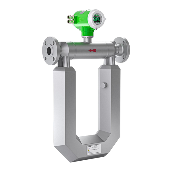
EMIS-MASS 260 OPERATION MANUAL 1.2 Structure and Operation Principle Flow meter consists of the following assemblies (fig.1.1): Electronic unit (1). Sensor (primary transducer) (2). Fig.1.1 - External view of flow meter Electronic unit can be mounted integrally with the flow meter (integral version, fig.1.1 a) and separately from the flow meter (remote version, fig.1.1 b). - Page 7 EMIS-MASS 260 OPERATION MANUAL Fig.1.2 - The forces affecting the tube during the vertical movement Fig.1.2: a) flow meter without power supply; b) power supplied, the coil cause the vibration in the measuring tubes; c) flow supply, generation of Coriolis effect.
- Page 8 Detailed description of each type is presented in the Operation manuals EM- 260.000.000.002.01 or EM-260.000.000.000.01. Operation manuals can be found in the website www.emis- kip.ru/ru/books1 in the related section EMIS-MASS 260. Measurement advantages: • direct measurement of mass flow rate in the pipeline without changes in parameters leading to further inaccuracy.
-
Page 9: Order Sheet
Example of the completed order sheet: EMIS-МАСС-260 – Ex – 050K – И – Ж – 2,5 – 100 – 24 – А1 – 0,25 – 1,0 – 1,0 – У – SC – Е – GOST Table 1.1 - Flow meter configurations Explosion protection –... - Page 10 EMIS-MASS 260 OPERATION MANUAL Х Special config. Flow meter mounting Integral version - sensor and transmitter as integral assembly remote installation with cable length of 3m Remote version with cable length of XXm. Max length - 100m – for ex-proof configuration - 50m...
- Page 11 EMIS-MASS 260 OPERATION MANUAL digital RS-485 + pulse output signal (passive)+ current output signal 4-20mA (active) digital RS-485 + pulse output signal (passive)+ current output signal 4-20mA (passive) digital RS-485 + pulse output signal (active)+ current output signal 4-20mA with digital HART...
- Page 12 EMIS-MASS 260 OPERATION MANUAL Error for liquid and gas ±5,0 kg/m Error for liquid and gas ±10,0 kg/m 10.0 After simulation test density measurement error is ±20,0 kg/m Upon prior agreement, for liquid only. Temperature error Standard error ±1,0°С Error ±0,5°С...
- Page 13 Mounting kit parts are listed in the table 1.2. Example of the completed order sheet: Mounting kit EMIS - MASS 260 050 - 2.5 - 11 - F - GOST - 09G2S Table 1.2 - Mounting kit versions Flow tube diameter...
- Page 14 EMIS-MASS 260 OPERATION MANUAL max pressure - 2,5 MPa max pressure - 16 MPa max pressure - 4,0 MPa max pressure - 25 MPa max pressure - 6,3 MPa Flange type Flat flange Weld neck flange Sealing surface Flange connection, flange face - type B “Raised face” under GOST 33259...
- Page 15 EMIS-MASS 260 OPERATION MANUAL 09G2С Steel 09G2S Ст20 Steel 20 Н Stainless steel 12Х18Н10Т 13ХFА Steel 13ХFА Х by order...
-
Page 16: Technical Parameters
EMIS-MASS 260 OPERATION MANUAL 1.4 Technical Parameters 1.4.1 Brief description of technical parameters Brief description of technical parameters is shown in Table 1.3 Table 1.3 - Technical parameters of flow meter Name Description Dn, mm 10; 15; 25; 40; 50; 80; 100; 150; 200 Accuracy 0,1;... -
Page 17: Measuring Ranges
Sensor tubes - stainless steel AISI 316L. Electronic unit - aluminum alloy Does not contain precious metals. * Upon prior agreement with EMIS engineering service. Note: You can customize flow meter parameters according your specific demands. 1.4.2 Measuring ranges Flow meter provides mass flow measurement with accuracy of δ... - Page 18 EMIS-MASS 260 OPERATION MANUAL 3,000 9,000 10,000 9,000 10,000 3,600 2,400 25,000 2,200 1,500 35,000 1.28 2,200 1,500 35,000 1.28 3,600 2,400 25,000 50К 5,000 3,500 50,000 3,500 2,500 55,000 3,500 2,500 55,000 5,000 3,500 50,000 80К 12,000 8,000 140,000...
- Page 19 EMIS-MASS 260 OPERATION MANUAL Table 1.4.2 - Extended liquid flow ranges Qmin, kg/h Qmin, Zero stability, Configuration Accuracy class kg/h kg/h kg/h 0,25 и 0,5 0.1; 0.15; 0.2; – 1,600 0.04 – 1,600 0.04 4,600 4,600 14,000 14,000 14,000 14,000...
- Page 20 EMIS-MASS 260 OPERATION MANUAL Table 1.5 - Mass flow rate measuring ranges for gas Qmin, kg/h Qmin, Zero stability, (mg)max Configuration Accuracy class kg/h , kg/h kg/h 0,25 и 0,5 0.1, 0.15, 0.2 – 15.7∙ρ 0.04 – 0.04 15.7∙ρ 42.9∙ρ...
-
Page 21: Pressure Configurations
It is not allowed to operate the flow meter at flow rates higher than stated maximum value. 1.4.3 Pressure configurations Table 1.6 shows versions of the EMIS-MASS 260 flange flow meter depending on the type of the casing, nominal diameter and the maximum pressure of the measured medium. -
Page 22: Accuracy
EMIS-MASS 260 OPERATION MANUAL - available version; 1.4.4 Accuracy Relative error limits for mass flow measurement of liquid δ on pulse, frequency, current TA and digital... -
Page 23: Parameters Of Electrical Power Supply
EMIS-MASS 260 OPERATION MANUAL Absolute error limits for measurement of gas density ∆ρ on frequency and digital output signals shall not exceed the values specified for flow meter configuration as below: ±1.0 kg/m ; ±2.0 kg/m ; ±5.0 kg/m ; ±10.0 kg/m... - Page 24 EMIS-MASS 260 OPERATION MANUAL discrete. Digital output signals: Modbus (RTU, ASCII) with RS-485; HART v7 on current loop 4-20 mA; Modbus TCP with Ethernet; Modbus (RTU, ASCII) with USB-485;* *Service interface. Used for flow meter adjustment.
-
Page 25: Flow Meter Reliability Parameters
Minimum medium pressure after the flow meter shall be not less than 0.1 MPa. 1.6 Explosion protection Ex-proof flow meters EMIS-MASS 260-Ex, ExBB, RV, RO-RV, RO-RVBB are equipped with ex-proof enclosure “d” under GOST IEC 60079-1-2013, intrinsically safe circuit of “ia” or "ib" protection level under GOST 31610.11-2014 (IEC 60079-11:2011). - Page 26 EMIS-MASS 260 OPERATION MANUAL IEC 60079-1-2013. Ex-proof connections parameters: axial length of the thread and the number of full turns in the engagement shall comply with the requirement of GOST IEC 60079-1-2013 for II group electrical equipment; Inspection window is sealed inside the metal rim of the casing cover to provide integrity;...
- Page 27 EMIS-MASS 260 OPERATION MANUAL - flow meters with steel body shall be used in underground mines, pits and its overground facilities hazardous with mine gas; - use certified cable glands and plugs to provide required type and level of explosion protection under GOST 14254 2015 (IEC 60529:2013).
- Page 28 EMIS-MASS 260 OPERATION MANUAL , µH....................0.002 - permissible external inductance L Electrical parameters of intrinsically safe electronic unit of “RO-RVBB” configuration: Power supply circuit: - max input voltage Ui, V..........................27 - max input current Ii, mA ..........................824 - max input power Pi, W ..........................
-
Page 29: Marking
EMIS-MASS 260 OPERATION MANUAL 1.7 Marking Marking is applied on the plates attached to the flow meter body. The flow meter has the following plates: Nameplate with technical parameters. For ex-proof flow meters - plate with explosion protection parameters. The nameplate is shown in fig.1.3 and contain the data as listed in the table 1.10. -
Page 30: Scope Of Supply
Flow meter general view for different configurations Point of sealing Fig.1.5 Sealing types of EMIS-MASS 260 depending on electronic unit configuration. 1.8 Scope of Supply Standard supply scope is presented in the fig.1.6 and described in the table 1.11. Additional supply kit is... - Page 31 EMIS-MASS 260 OPERATION MANUAL Fig.1.6 - Standard scope of supply...
- Page 32 EMIS, CJSC Certificates* Notes: *List of certificates is presented in the table 1.15; ** Manuals for different types of electronic unit are available on the web-site of EMIS, CJSC. Printed version provided upon request. Fig. 1.7 - Additional supply kit...
- Page 33 Table 1.12 - Additional supply kit NO in Description fig. Mounting kit (flanges, gaskets, nuts, washers, studs) EMIS-MASS 260 -MK Mounting sleeve EMIS-VECTA VT300 Mounting kit for remote type flow meter* (Support bar mounting bracket Ø50-100mm; clamps, nuts, washers) Spare parts kit, tools and accessories** Notes: *Mounting kit for remote type flow meter is presented in the Appendix A;...
-
Page 34: Intended Use
EMIS-MASS 260 OPERATION MANUAL 2 Intended Use 2.1 Configuration selection To provide reliable work and accuracy of the flow meter it is important to match equipment version with your technological process. Process information needed for equipment selection is listed in table 2.1. -
Page 35: Mounting On The Pipeline
EMIS-MASS 260 OPERATION MANUAL to replace radio components if power is connected; connect to power supply source with output voltage different from specified in the Manual; use electrical units without grounding or in case of malfunction. The factors below can be dangerous: ... -
Page 36: Pipeline Direction
EMIS-MASS 260 OPERATION MANUAL Ambient temperature of installation point shall be in the range from -60 to +70°С. Under direct sun light the temperature of the flow meter body can exceed environment temperature up to 30 degrees. Sun shield shall be installed if no shade is available. -
Page 37: Preparation Of Pipeline
EMIS-MASS 260 OPERATION MANUAL Fig.2.3 - Installation guide for EMIS-MASS 260 Table 2.3 - Description for fig.2.3 NO in Recommendations fig.2.2 Install flow meter with measuring chamber downward to provide filling with liquid and avoid gas accumulation in tubes. Install flow meter with measuring chamber upward for gas measurement to avoid moisture condensation. - Page 38 EMIS-MASS 260 OPERATION MANUAL Lgas - gasket width; Lfl- counter flange width after deduction of installation length; mount counter flanges in the pipeline; use mounting coupling to align flanges, them weld them to the pipeline. Attention! It is allowed to use flow meter as mounting coupling in cases listed below: - gas welding is used for mounting;...
-
Page 39: Pipe Body Preparation And Flow Meter Mounting
tighten the nuts in the sequence shown in fig.2.7 Attention! Avoid bending and twisting loads upon connection points, and mismatch of pipeline counter connections. Fig.2.6 - Installation of EMIS-MASS 260 in the pipeline Table 2.4 - Description for fig.2.6 NO in fig. Description... - Page 40 EMIS-MASS 260 OPERATION MANUAL Gaskets Nuts Washers Pins Fig.2.7 - Tightening sequence for flange bolts Remote type flow meter is shown in the fig.2.8. Electronic unit can be fixed to the support bar using the mounting bracket or the wall using the additional mounting kit for remote type electronic unit (supplied upon request, see Appendix A) Fig.2.8.1 - Installation options for standard electronic unit of remote type flow meter...
-
Page 41: Heat Insulation
EMIS-MASS 260 OPERATION MANUAL Fig.2.8.2 - Installation options for extended electronic unit of remote type flow meter Table 2.5 - Description for fig.2.8 NO in fig. Description Remote type electronic unit Bolts (not included in the standard supply kit) Clamps (not included in the standard supply kit) -
Page 42: Preheating
EMIS-MASS 260 OPERATION MANUAL Fig.2.9 - Heat insulation recommendations 2.3.6 Preheating The flow meter can be equipped with the inlet for connection of external heating (see fig.2.10) upon special request. Liquid or gas (vapour) at temperature less than 200˚С and pressure not less than 0.1 MPa can be used for heating. - Page 43 OPERATION MANUAL Fig.2.11 - Rotation of electronic unit Attention! To avoid wires twisting inside the flow meter, do not rotate more than 180° from initial position. Notify EMIS maintenance service prior to the rotation of electronic unit to keep warranty.
-
Page 44: Power Connection
EMIS-MASS 260 OPERATION MANUAL 2.4 Power connection Attention! All connections shall be executed when flow meter is not connected to power supply. Electrical connection shall be performed by the certified specialists corresponding qualification and permission. Electrical crew shall follow effective federal and national security regulations. -
Page 45: Explosion Protection While Mounting
For installation in explosive environment strictly follow the rules listed in clause 2.4.2 “Explosion protection while mounting”. Attention! Contact your local EMIS dealer if any assistance for electrical mounting is required. 2.4.2 Explosion protection while mounting Installation in explosive environment shall comply with the requirement listed below: –... - Page 46 EMIS-MASS 260 OPERATION MANUAL Plug unused cable glands with the plug supplied or any other plug certified under GOST IEC 60079-1- 2013. Examine all ex-proof surfaces which will be unmounted. No scratches, indention, shears on the surfaces marked as ex-proof on the drawing in Appendix B are allowed.
-
Page 47: Connection Recommendations
EMIS-MASS 260 OPERATION MANUAL 2.4.3 Connection recommendations Follow the directions below for electrical mounting: - cable cores shall be protected and connected to terminals so that to avoid electric cross and fault to the meter body; - use different power suppliers for flow meter and each of its output signals or multichannel supplier with galvanically isolated windings. -
Page 48: Grounding
EMIS-MASS 260 OPERATION MANUAL 2.4.5 Grounding Transient phenomena due to lightning, welding, powerful electrical units or distribution boards may cause readings mistakes or damage the flow meter. To protect from transient phenomena provide the flow meter grounding according to the clause “Electrical connection” of the EM-260 Operation manual (EM- 260.000.000.002.01 OM or EM-260.000.000.000.01 OM) depending on the flow meter configuration. - Page 49 EMIS-MASS 260 OPERATION MANUAL To use corrosive washing fluid; To exceed flow range specified for the flow meter. If washing is executed using the medium in physical form other than specified in the flow meter marking, use the values specified in the tables 1.4 and 1.5.
-
Page 50: Transportation, Storage And Recycling
EMIS-MASS 260 OPERATION MANUAL 3 Transportation, Storage and Recycling 3.1 Transportation Please follow the transportation requirements: flow meter shall be packed so to avoid mechanical damages during transportation; line the inner part of transportation package with water-resistant paper;... -
Page 51: Recycling
EMIS-MASS 260 OPERATION MANUAL Flow meters can be stored in transportation boxes stacked up to 3 boxes in height or without package. Long-term storage shall be provided in manufacturer package. 3.3 Recycling Flow meters does not contain hazardous materials or components dangerous to people health or the environment during service life and recycling. -
Page 52: Calibration
Calibration shall be provided according to the CM 208-043-2019 “GSI. CORIOLIS FLOW METER EMIS- MASS 260”. Calibration method MI- 3272-2010 GSI. On-site calibration procedure using a compact prover in set with a turbine flow transducer and flow density transducer", "MI 3151-2008 GSI. Mass flow meters. On-site calibration using mechanical displacement meter prover in set with density converter”, MI 3313-2011 GSI. -
Page 53: List Of Possible Failures
EMIS-MASS 260 OPERATION MANUAL 5 List of possible failures 5.1 List of possible failures (including critical) - Seal failure of body; - Welding seams damage; 5.2 Personell mistakes leading to failure, emergency or accidents To provide safety operation, it is prohibited to: –... - Page 54 Cmax А.1.1 А.1.2 Figure A.1 - Dimensions and connection size of EMIS-MASS 260 Dn10 standard configuration and Dn15 FR version A.1.1 - Integral version; A.1.2 - Remote version. Connection sizes of flow meter flanges are presented on the pages 48, 49.
- Page 55 Cmax А.2.1 А.2.2 Figure A.2 - Dimensions and connection size of EMIS-MASS 260 Dn25, Dn40 and Dn80 standard configuration A.2.1 - Integral version; A.2.2 - Remote version. Connection sizes of flow meter flanges are presented on the pages 48, 49.
- Page 56 Cmax А.3.1 А.3.2 Dimensions and connection size of EMIS-MASS 260 Dn100, Dn150 and Dn200 standard configuration A.3.1 - Integral version; A.32.2 - Remote version. Connection sizes of flow meter flanges are presented on the pages 48, 49. Electronic unit dimensions are presented on the pages 53, 54.
- Page 57 OPERATION MANUAL Cmax А.4.1 А.4.2 Dimensions and connection size of EMIS-MASS 260 Dn15C, Dn25C, Dn40C, Dn50C and Dn80C compact configuration A.4.1 - Integral version; A4.2 - Remote version. Connection sizes of flow meter flanges are presented on the pages 48, 49.
- Page 58 OPERATION MANUAL Cmax А.5.1 А.5.2 Dimensions and connection size of EMIS-MASS 260 Dn100C, Dn150C and Dn200C compact configuration A.5.1 - Integral version; A5.2 - Remote version. Connection sizes of flow meter flanges are presented on the pages 48, 49. Electronic unit dimensions are presented on the pages 53, 54 Table A.5...
- Page 59 EMIS-MASS 260 OPERATION MANUAL Count Fig. А.6 – Connection flange sizes of EMIS-MASS 260. Main type of connection surface for 6.3 Mpa complies with E configuration under GOST 33259. Other connection sizes can be provided upon request. Table A.6 Pu, MPa...
- Page 60 EMIS-MASS 260 OPERATION MANUAL Count Fig. А.7 – Connection flange sizes Main type of connection surface for 10 MPa complies with J configuration under GOST 33259. Other connection sizes can be provided upon request. Table A.7 Size Pu, MPa D, mm...
- Page 61 EMIS-MASS 260 OPERATION MANUAL Fig. А.8 – Connection flange and counter flange size Counter flange of type 01 “Flat welding flange” GOST 33259, flange type according to order sheet. Flange face complies with type F “Female” under GOST 33259. Other connection sizes can be provided upon request.
- Page 62 EMIS-MASS 260 OPERATION MANUAL Н Count. Fig. А.9 – Connection flange and counter flange weight Counter flange of type 11 “Weld neck flange” GOST 33259, flange type according to order sheet. Flange face complies with type F Female under GOST 33259. Other connection sizes can be provided upon request.
- Page 63 EMIS-MASS 260 OPERATION MANUAL Н Count Fig. А.10 – Connection flange and counter flange weight Counter flange of type 11 “Weld neck flange” GOST 33259. Flange face - complies with type J “Oval gasket” under GOST 33259. Table A.10 Weight, kg...
- Page 64 EMIS-MASS 260 OPERATION MANUAL Type A 4 count. Ø8.5 Figure A.11 - Dimensions and connection sizes of electronic unit of standard version, remote type flow meter EMIS-MASS 260.
- Page 65 EMIS-MASS 260 OPERATION MANUAL Figure A.12 Mounting bracket for standard electronic unit of remote type flow meter on the support bar. Table A.12 - Mounting kit for standard electronic unit, remote type flow meter. Part Amount Note Bracket For mounting on support bar up to Ø60mm...
- Page 66 OPERATION MANUAL Figure A.13 - Dimensions and connection sizes of electronic unit of extended version, remote type flow meter EMIS-MASS 260. Figure A.14 - Dimensions and connection sizes of electronic unit of extended version, remote type flow meter EMIS-MASS 260.
- Page 67 EMIS-MASS 260 OPERATION MANUAL Figure A.13 - Dimensions and connection sizes of electronic unit of extended version, remote type flow meter EMIS-MASS 260. Part Amount Note Clamp 1¾” For mounting on support bar up to Ø57mm 2 pcs Nut M8...
- Page 68 EMIS-MASS 260 OPERATION MANUAL Appendix B List of normative documents Name Name Menu Explosive mediums Part 11. Equipment with protection type GOST 31610.11-2014 1.1, 1.5, 1.6, 2.4.2 "intrinsically safe circuit "i". Explosive mediums Part 1. Equipment with protection type GOST IEC 60079-1-2013 1.1, 1.5, 2.4.2...
- Page 69 Measurement technique Application: Present manual describes EMIS-MASS 260 measuring technique of mass flow and mass, density, temperature, volume flow and volume of liquids, volume flow, volume, mass flow and temperature of gases. This technique is applicable for flow meters installed at commercial and technological metering units.
- Page 70 EMIS-MASS 260 OPERATION MANUAL 3.15 Metering unit: Metering devices providing metering of medium flow and amount, as well as defining its quality parameters. 3.16 Commercial metering unit: Metering unit providing accounting for the purpose of seller and buyer. 3.17 Cost accounting unit: Metering unit for cost accounting of production within the operating entity.
- Page 71 EMIS-MASS 260 OPERATION MANUAL Operation manual shall be available for the maintenance personell. Gas and liquids measuring methods. Measuring conditions. 7.1.1 Medium type 7.1.1.1 Measuring medium is gas or liquid in single-phase state during measurement. 7.1.1.2 Possibility of flow meter operation shall be agreed with the manufacturer in the following cases: for liquids: ...
- Page 72 EMIS-MASS 260 OPERATION MANUAL Set the low flow cut-off value (if required); Adjust totalizers; Adjust output signals according to the input parameters of the auxiliary devices. Adjust digital interface (Modbus or HART) according to the auxiliary devices interface.
- Page 73 EMIS-MASS 260 OPERATION MANUAL - measured value at 4mA, MV units; and V can be specified in the flow meter current output signal settings. 7.4.2.4 RS-485 transfers measured values in the form of numeric values, units are specified in the registry map.
- Page 74 EMIS-MASS 260 OPERATION MANUAL 7.5.2.2.2 For control purpose, check controlled parameters (weight, volume, density or temperature) not less than 3 times at stable medium flow. Accumulation time shall be not less than 30sec for each measurement. 7.5.2.2.3 Check result is positive if each measurement meets the following condition: ��...
Need help?
Do you have a question about the MASS 260 and is the answer not in the manual?
Questions and answers