
Subscribe to Our Youtube Channel
Related Manuals for RadioLink R8FG

Summary of Contents for RadioLink R8FG
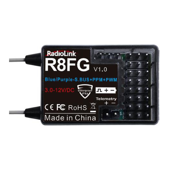
- Page 1 R8FG (FHSS) INSTRUCTION MANUAL Two-way Transmission PWM&PPM&SBUS Signal Supported 8-channel Receiver with Integrated Gyro...
- Page 2 If any problems found during the operation process, either way listed below can be used as online tech support. 1. Send mails to after_service@radiolink.com.cn and we will answer your question at the earliest. 2. Send private message to us on our Facebook page or leave comments on our YouTube page 3.
-
Page 3: Table Of Contents
RadioLink Electronic Ltd www.radiolink.com Contents 1. R8FG Introduction ........................... 3 1.1 Compatible transmitters ......................... 3 1.2 Binding ............................3 2. Telemetry ..............................3 2.1 Telemetry of Signal and RSSI ......................4 2.2 Telemetry of model battery and receiver voltage ................5 3. -
Page 4: R8Fg Introduction
② Turn on both the transmitter and the receiver, and then the LED of R8FG will start flashing slowly. ③ There is a black binding button (ID SET) on the side of the receiver. Press the button for more than 1 second and release, the LED will flash quickly, indicating the binding process is ongoing. -
Page 5: Telemetry Of Signal And Rssi
RC8X if the binding is successful and the telemetry cable is connected correctly. RC8X home page: 2.1 Telemetry of Signal and RSSI Power on RC8X and R8FG receiver, and then bind them. Signal and RSSI will be displayed on the homepage of transmitter after successful binding. -
Page 6: Telemetry Of Model Battery And Receiver Voltage
60 centimeters, it is normal that RSSI value is within the range of 0 to -30dBm. The closer the value is to 0, the stronger the signal is. The range of RSSI value of RadioLink transmitters is from 0 to -99dBm. -
Page 7: Child Id
R8FG/R7FG/R8F as below pic shown. No extra module is needed. Attention: 1. Reverse polarity protection circuit design for all 8 channels of R8FG ensures vital components are protected from a reverse polarity connection. But, the JST connector which is packed with R8FG for connecting to the battery cannot reverse polarity connect, or it will lead to the wrong voltage value telemetry. -
Page 8: Working Modes
ID number back to ID_0. 4. Working Modes R8FG has a built-in gyroscope, which can output not only PWM signals but also PPM and SBUS signals. There are four working modes, including ordinary PWM mode, SBUS mode, Gyro mode, and Gyro + SBUS mode. -
Page 9: Working Mode Setting
5.2 Gyro Enable The gyro function of R8FG is turned off by default. Since the integrated gyro in R8FG will self-check, it is important to keep R8FG still when powering it on. Red LED is the gyro status indicator . When the red LED off means NO gyro. -
Page 10: Gyro Sensitivity Adjustment
If the value is 0, it means the gyro function has been turned off. You can also assign other switches to control the gyro function or adjust the sensitivity on this page. 6. R8FG Specifications R8FG Receiver Dimensions L*W*H =35*24*13.5mm (1.38"*0.94"*0.53") - Page 11 Keeping the receiver in a well sealed plastic bag can avoid humidity and dust, which would possibly make the receiver out of control. When all the above steps are complete, please turn off the transmitter and repower on to test if the receiver is correctly bind with it. Thank you again for choosing RadioLink product.
Need help?
Do you have a question about the R8FG and is the answer not in the manual?
Questions and answers