Table of Contents
Advertisement
Quick Links
SECURE TERMINAL EQUIPMENT (STE)
USER'S MANUAL
Release 2.6
Rev A January 2008
Prepared by:
L-3 Communications
Communication Systems – East
One Federal Street
Camden, NJ 08103-1013
THE INFORMATION CONTAINED HEREIN IS SUBJECT TO THE U.S. EXPORT CONTROL LAWS
AND MAY NOT BE EXPORTED, RELEASED, OR DISCLOSED TO FOREIGN PERSONS INSIDE OR
OUTSIDE THE U.S. WITHOUT OBTAINING PROPER APPROVALS.
Control Number: K00011722
Advertisement
Table of Contents

Summary of Contents for L-3 Communications Office STE
- Page 1 SECURE TERMINAL EQUIPMENT (STE) USER’S MANUAL Release 2.6 Rev A January 2008 Prepared by: L-3 Communications Communication Systems – East One Federal Street Camden, NJ 08103-1013 THE INFORMATION CONTAINED HEREIN IS SUBJECT TO THE U.S. EXPORT CONTROL LAWS AND MAY NOT BE EXPORTED, RELEASED, OR DISCLOSED TO FOREIGN PERSONS INSIDE OR OUTSIDE THE U.S.
- Page 2 Copyright 2006, L-3 Communications Corporation...
- Page 3 This User’s Manual describes the features and operating procedures for the following Secure Terminal Equipment (STE) configurations operating under software Release 2.6: • Desk Sets Office STE, part number K10046389 (Series) Tactical STE, part number K10048389 (Series) • Desk Stack or Rack...
- Page 4 Preface STE User’s Manual Chapter 6, “Crypto Card Management” is intended for all users. It provides: • Procedures to rekey crypto cards and to view key data, • Procedures to zeroize keys and view CKL/CIM reports, and • Procedures to zeroize the STE. Chapter 7, “Voice Operation”, is intended for all operators.
- Page 5 STE User’s Manual Preface Chapter 9, “8510 Capabilities”, is intended for all 8510 users. It provides: • Introduction to the 8510 feature, • Non-secure calling, • Switch features support, • 5ESS secure calling, • DEFINITY secure calling, and • Setting up the STE-8510. Chapter 10, “External Utilities”, is primarily intended for the TPA.
- Page 6 Preface STE User’s Manual • STU-III Voice and Data • EIA-232/EIA-530A Red Serial Data Port • 128 kbps Synchronous Data Mode • Remote Control (AT Commands) • Secure Call set-up in less than 2-seconds • Secure Access Control System (SACS) •...
- Page 7 STE User’s Manual Preface • G.729D Secure Dial & Remote Control • International PSTN (Software Only) • NP RAM update (to support IP STE) • Speaker Phone Volume • STE Secure Dial • Tactical FNBDT and Tactical STE-R (non T1 IWF support) •...
- Page 8 List of Effective Pages Page(s) Release a - j i - xiv 1-1 – 1-6 2-1 – 2-48 3-1 – 3-12 4-1 – 4-40 5-1 – 5-24 6-1 – 6-24 7-1 – 7-28 8-1 – 8-24 9-1 – 9-24 10-1 – 10-20 11-1 –...
-
Page 9: Revision Log
STE User’s Manual Revision Log Revision Log Revision Change Summary September 2007 – Release 2.6 January 2008 – Release 2.6 Rel. 2.6... - Page 10 List of Acronyms STE User’s Manual List of Acronyms Acronyms Meaning 5th-release Electronic Switching System (digital switch) 5ESS Acknowledgement Access Control List Additional Call Offering ADPCM Adaptive Differential PCM Automatic Number Identification ASYNC Asynchronous AUTOVON AUTOmatic VOice Network Black Digital Interface Basic Firefly Basic Rate Interface CACH...
- Page 11 STE User’s Manual List of Acronyms List of Acronyms Acronyms Meaning Frequently Asked Question Federal Communications Commission FNBDT Future Narrow Band Digital Terminal Graphical User Interface Gateway GW/IWF Gateway/Interworking Function Human Machine Interface Identification, Identifier ISDN Integrated Services Digital Network Inter-Working Function kbps Kilobits per second...
- Page 12 List of Acronyms STE User’s Manual List of Acronyms Acronyms Meaning SCRQ/ID STE Secure Request Patter Secure Data SDNS Secure Data Network System SECAPP Secure Applications SPID Service Profile Identifier Secure Terminal Equipment STE-R STE Remote, Voice & Data – ISDN & PSTN STE-RI STE Remote, Voice &...
-
Page 13: Table Of Contents
List of Illustrations ............................. vi List of Tables ............................xiii Chapter 1 INTRODUCTION......................1-1 1-1. OFFICE STE AND TACTICAL STE DESK SETS ............1-1 1-2. DATA STE AND STE-R TERMINALS ................1-2 1-3. L-3 STE SERVICE CENTER ................... 1-3 1-4. - Page 14 Table of Contents STE User’s Manual 2-6.6 ADVANCED TERMINAL SETTINGS FOR INSTALLATION PERSONNEL (PSTN) ..2-32 2-6.7 Connect PSTN Port......................2-35 2-7. INSTALL TRI-TAC ......................2-35 2-7.1 TRI-TAC Pre-installation Requirements.................2-35 2-7.2 Set the ACTIVE NETWORK PORT to TRI-TAC............2-36 2-7.3 ADVANCED TERMINAL SETTINGS FOR INSTALLATION PERSONNEL (TRI-TAC) 2-37 2-7.4 Connect TRI-TAC Port....................
- Page 15 STE User’s Manual Table of Contents 5-1.3 Transfer TPA Privileges ....................5-6 5-1.4 Audible Alerts ........................5-6 5-1.5 Terminal Control.......................5-6 5-1.6 Auto-Answer........................5-7 5-1.7 Data Port .......................... 5-8 5-1.8 Remote Control Data Port Rate ..................5-9 5-1.9 Handset Sidetone......................5-9 5-1.10 Ring Selection ........................
- Page 16 Table of Contents STE User’s Manual 7-3.9 ISDN - Managing Multiple Calls ..................7-17 7-4. TRI-TAC VOICE CALLS ....................7-21 7-4.1 TRI-TAC - Initiating Calls ....................7-21 7-4.2 TRI-TAC - Answering Calls.................... 7-22 7-4.3 TRI-TAC - Call Hold ....................... 7-23 7-4.4 TRI-TAC - Call Transfer ....................
- Page 17 STE User’s Manual Table of Contents 9-6.2 Receiving Secure Voice Calls on DEFINITY With STE-8510........9-14 9-6.3 Secure Data Calls on DEFINITY..................9-14 9-7. SETTING UP STE-8510 ....................9-15 9-7.1 Setting the STE 8510 Switch Type ................9-15 9-7.2 5ESS Configuration......................9-19 9-7.3 DEFINITY Configuration ....................
-
Page 18: List Of Illustrations
List of Illustrations STE User’s Manual List of Illustrations Figure Title Page Figure 1-1. STE Configurations ........................1-1 Figure 1-2. Typical Office/Tactical STE Desk Set..................1-2 Figure 1-3. Typical Data STE, STE-R and STE-RT..................1-3 Figure 1-4. Typical CEU and STE-RI......................1-3 Figure 2-1. STE Rear Views ........................2-3 Figure 2-2. - Page 19 STE User’s Manual List of Illustrations Figure 2-49. STU/SCIP EXTENDED TIMEOUT Menu ................2-33 Figure 2-50. STU/SCIP EXTENDED TIMEOUT Menu ................2-33 Figure 2-51. FADE TIMEOUT Menu.......................2-34 Figure 2-52. ENTER FADE TIMEOUT Menu..................2-34 Figure 2-53. Tactical Wedge Adapter Assembly..................2-36 Figure 2-54. TERMINAL MANAGEMENT Menu..................2-37 Figure 2-55.
- Page 20 List of Illustrations STE User’s Manual Figure 4-17. PREPARE REMOTE ASSOCIATION Menu ..............4-11 Figure 4-18. PREPARE REMOTE ASSOCIATION/Complete Menu............4-12 Figure 4-19. Associated Carry Card .......................4-13 Figure 4-20. User Card – Dual Association ....................4-14 Figure 4-21. CHANGE TPA PASSWORD Menu ..................4-15 Figure 4-22.
- Page 21 STE User’s Manual List of Illustrations Figure 5-1. Terminal Management Menu....................5-1 Figure 5-2. Network Settings Menu ......................5-2 Figure 5-3. Terminal Privileges, Association and Software Update Management Menu ......5-2 Figure 5-4. Terminal Audit Information Menu ...................5-2 Figure 5-5. Software Update TPA/Configuration TPA Menu ..............5-3 Figure 5-6.
- Page 22 List of Illustrations STE User’s Manual Figure 6-7. STU-III New Number Entry Menu...................6-3 Figure 6-8. SDNS Rekey Phone Number / Select Type Menu ..............6-4 Figure 6-9. SDNS Enter New Number to Change Menu ................6-4 Figure 6-10. SDNS New Number Entry Number ..................6-5 Figure 6-11.
- Page 23 STE User’s Manual List of Illustrations Figure 7-1. PSTN Auto-Secure Off-Hook Menu ..................7-6 Figure 7-2. PSTN Traditional Off-Hook Menu...................7-6 Figure 7-3. PSTN Secure-Only Off-Hook Menu..................7-7 Figure 7-4. PSTN Incoming Call Menu .....................7-7 Figure 7-5. PSTN Incoming Call – Off-Hook Menu...................7-8 Figure 7-6.
- Page 24 List of Illustrations STE User’s Manual Figure 10-2. Software Download Log File....................10-5 Figure 10-3. STE Virtual Front Panel Tool....................10-8 Figure 10-4. STE Logfile Notepad Window....................10-9 Figure 10-5. STE Toolset Options ─ Terminal Type (Default Window) ..........10-10 Figure 10-6. STE Toolset Options ─ Terminal Type................10-11 Figure 10-7.
- Page 25 Table Title Page Table 1-1. Technical Specifications ......................1-4 Table 2-1. Office STE Packing Container Contents .................2-1 Table 2-2. Tactical STE Packing Container Contents ................2-1 Table 2-3. Data STE Packing Container Contents ...................2-2 Table 2-4. STE-R Packing Container Contents ..................2-2 Table 2-5. STE-RT Packing Container Contents ..................2-2 Table 2-6.
- Page 26 List of Tables STE User’s Manual This page intentionally left blank. Rel. 2.6...
-
Page 27: Chapter 1 Introduction
International adapter is “United States”. Actions required to prepare the International Adapter for in other countries is addressed in Chapter 2. The Office STE operates under local control (dial pad) for voice and data operation and under remote control, via a connected Personal Computer (PC), for data operations. -
Page 28: Data Ste And Ste-R Terminals
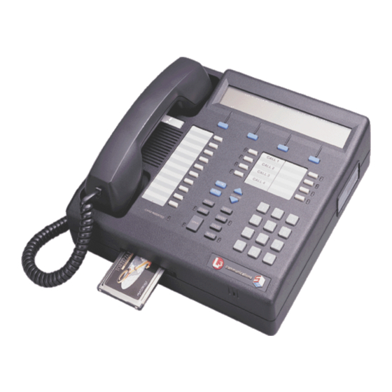
Introduction STE User’s Manual Figure 1-2. Typical Office/Tactical STE Desk Set The Tactical STE Desk Set provides access to ISDN, PSTN (Conventional only), TRI-TAC (TRI-service TACtical), and serial EIA-530A/EIA-232 BDI (Black Digital Interface) telecommunications systems for voice and data operation. The Tactical STE operates under local control (dial pad) for voice and data operation and under remote control, via a connected PC, for data operations. -
Page 29: L-3 Ste Service Center
SCIP terminals when they function as a gateway device for interfacing red switches with STE, STU-III, and SCIP terminals on black “dial-up” PSTN or ISDN systems. 1-3. L-3 STE SERVICE CENTER L-3 Communications Communication Systems – East STE Service Center 11 Federal Street... -
Page 30: Technical Specifications
Introduction STE User’s Manual 1-4. TECHNICAL SPECIFICATIONS Table 1-1. Technical Specifications Voice • • Secure Voice: ADPCM @ 32 kbps • CELP @ 4.8 kbps • LPC-10e @ 2.4 kbps • MELP @ 2.4 kbps, 4.8 kbps • G.729D @ 6.4 kbps •... -
Page 31: Safety Instructions
STE User’s Manual Introduction Table 1.1. Technical Specifications (Continued) Environmental: • to 104 F (0 to 40 Operating Temperature 10% to 90% Non-condensing • Operating Relative Humidity to 140 F (-20 to 60 • Storage Temperature Power: STE External Power Supply, 100-250 VAC (-10%, +6%);... - Page 32 Introduction STE User’s Manual This page intentionally left blank. Rel. 2.6...
-
Page 33: Chapter 2 Installation
If the STE Terminal (an assembly made up of a base STE and either an Office Wedge or a Tactical Wedge) shows signs of damage, DO NOT proceed with the installation. Send the terminal back to L-3 Communications. Refer to Chapter 12 for details. -
Page 34: Table 2-3. Data Ste Packing Container Contents
Installation STE User’s Manual Table 2-3. Data STE Packing Container Contents Quantity Description Part Number K10047778-508 (REL 2 HW) Data STE Terminal K10047778-509 (REL 3 HW) AC-DC Power Supply K10046396-1 ISDN Line Cord URT45-M4N-12-BK PSTN Line Cord H1442-14-ND Console Cable K10047819-1 STE Software and Documentation Support K10048750-series... -
Page 35: Ste Arrangement
STE User’s Manual Installation 2-2. STE ARRANGEMENT Controls and interface ports located on the rear panel of the STEs are shown in Figure 2-1. RED EXPANSION BLACK EXPANSION PORT PORT RED SERIAL DATA PORT 1 ISDN TERMINATION POWER PORT SWITCHES ISDN PORT PSTN PORT TRI-TAC PORT... -
Page 36: 2-2.2 Ports Located In The Wedges
2-3. GENERAL PRE-INSTALLATION REQUIREMENTS Before you install your STE, you should determine the following: Identify the type of STE you wish to install (CEU, Office STE, STE-R, STE-RI, STE-RT, Digital • STE or Tactical STE). You can connect an Office STE or STE-R to either an ISDN or PSTN. -
Page 37: Power Port Pre-Installation Requirements
STE User’s Manual Installation must be done to obtain any services not presently available. Abide by local regulations for phone installations and maintenance. Last, you must also order your EFF card KOV-14L or KSV-21 or you use your older BFF KOV-14, •... -
Page 38: 2-3.3 Red Audio Port Pre-Installation Requirements
Installation STE User’s Manual The CONSOLE PORT, an RJ-8 socket, is located in the Front Panel to provide an RS-232 interface at 38.4 kbps for a PC that will act as a Console Terminal to configure the STEs. The CONSOLE PORT pin- outs are provided in Table 2-10. -
Page 39: General Installation Procedures
STE User’s Manual Installation 2-3.4 Order Your FORTEZZA PLUS ENHANCED CRYPTOCARD KRYPTON™ You are responsible for ordering your KOV-14L, KSV-21, KOV-14, KOV-15 or SOV-16 crypto cards from the government; they are not included in your STE order. See the U.S. government web site (Paragraph 2-3.4.1) for ordering instructions. -
Page 40: Figure 2-2. Wall Mounting Plate And Wedge Positioning
Installation STE User’s Manual 0.135 0.079 PLATE MOUNTING 0.375 MOUNTING POST 4.500 3.950 2.375 0.181 SCREW HOLES (See side view) SIDE VIEW FRONT VIEW Rotate wedge 180 degrees to change mounting holes to look like Phillips head screws at four corners Crypto Card Slot Figure 2-2. -
Page 41: 2-4.2 Install Handset
STE User’s Manual Installation HOOK SWITCH HANDSET HOOK Figure 2-3. Handset Cradle Mount the STE on the Wall Mounting Plate then install the Handset as stated in Paragraph 2-4.2. 2-4.2 Install Handset Insert the plug on one end of the Handset Cord into the RJ-11 socket located on the left side of the Office or Tactical STE and the other end into the socket on the Handset. -
Page 42: 2-4.5 Install, Program, And Connect Service(S)
Installation STE User’s Manual (PUP) is used, make sure it is properly connected and turned on. Please refer to Chapter 11 troubleshooting procedures. TERMINAL RESETTING Figure 2-4 Terminal Resetting After approximately a 1-minute wait, the TERMINAL RESET message should appear (Figure 2-5) on your STE display. -
Page 43: Install Isdn
STE User’s Manual Installation 2-5. INSTALL ISDN 2-5.1 ISDN Pre-installation Requirements. The ISDN pre-installation requirements apply to all STEs to be used for operation using ISDN. 2-5.1.1 Order ISDN Service Contact your local facility telecom department or the service provider (Telephone Company) to order your ISDN service. - Page 44 Installation STE User’s Manual IOC Code/Line Options □ P, U, V, EZ ISDN-1 or □ P, U, V, EZ ISDN-1a DN #2 Connection Type □ 2-wire (U) – NT-1 required □ 4-wire (S/T) STEP 2: Determine Switch Type and Software Version. The STE is compatible with the protocols used by the following switches and associated PBX (Private Branch Exchanges).
-
Page 45: 2-5.2 Set Active Network Port To Isdn
STE User’s Manual Installation 1 is a small electronic box that, if you need one it must be purchased by a STE user. An example of an NT-1 is the Tone Commander NTIU-220TC. For more information about them, call 800-245-9780 or visit their web site at: http://www.tonecommander.com. -
Page 46: Figure 2-6. Terminal Management Menu
Installation STE User’s Manual Setting Default Feature Code Transfer Feature Code (set from Table 2-14) Conference Feature Code (set from Table 2-14) Drop Feature Code (set from Table 2-14) Advanced Terminal Settings for Installation Personnel STU-III ACK/NAK Enabled STU/SCIP Extended Timeout STE Extended Timeout Fade Timeout Initiate Direct Dial... -
Page 47: Set The Isdn Switch Type
STE User’s Manual Installation With the ACTIVE NETWORK PORT set to ISDN, press SCROLL (once) to advance to the SWITCH TYPE menu (Paragraph 2-5.3). Pressing BACK will return the display to the NETWORK SETTINGS menu (Figure 2-7). 2-5.3 Set the ISDN SWITCH TYPE The SWITCH TYPE display (Figure 2-9) shows the type of switch used for your ISDN service. -
Page 48: Set Directory Number #1
Installation STE User’s Manual If no change is required, or after making a new entry, press SCROLL to advance to the DIRECTORY NUMBER #1 menu (Paragraph 2-5.5). Press BACK to return the display to the NETWORK SETTINGS menu. 2-5.5 Set DIRECTORY NUMBER #1 The DIRECTORY NUMBER #1 menu (Figure 2-12) shows the primary directory telephone number... -
Page 49: 2-5.8 Set Feature Codes
STE User’s Manual Installation 2-5.8 Set FEATURE CODES The FEATURE CODES menu (Figure 2-14) will show the STE feature setting as either STANDARD or NONSTANDARD as represented by “aaaaaaaaaaaa”. These features reflect the ability of the switch to support conference calls, call transfer, or call drop. FEATURE CODES: aaaaaaaaaaaa SELECT SCROLL... -
Page 50: Figure 2-17. Transfer Feature Code Menu
Installation STE User’s Manual If no change is required, or after a change is completed, press SCROLL to advance to the TRANSFER FEATURE CODE menu (see Paragraph 2-5.8.2). Press BACK to return the display to the NETWORK SETTINGS menu (Figure 2-7). -
Page 51: Advanced Terminal Settings For Installation Personnel (Isdn)
STE User’s Manual Installation To change an existing code to one listed in Table 2-14 press CHANGE to advance the display to the ENTER DROP FEATURE CODE menu (Figure 2-20). ENTER DROP FEATURE CODE: STORE DELETE ABORT Figure 2-20. ENTER DROP FEATURE CODE: Menu Using the DIAL PAD KEYS, enter the Drop Feature data from the table, in a valid range between 000 and 127, as represented by “nnn”... -
Page 52: Figure 2-22. Stu-Iii Ack/Nack: Enabled Menu
Installation STE User’s Manual The STU-III ACK/NACK menu (Figure 2-22) shows the present setting. The default setting is “ENABLED. STU-III ACK/NACK: ENABLED CHANGE SCROLL BACK Figure 2-22. STU-III ACK/NACK: ENABLED Menu If the setting must be changed, pressing CHANGE toggles between ENABLED and DISABLED. When the setting is made, press SCROLL to advance to the STU-III EXTENDED TIMEOUT (Paragraph 2-5.9.2) menu also shared by all services. -
Page 53: Figure 2-25. Ste Extended Timeout: Menu
STE User’s Manual Installation Press BACK to return the display to the NETWORK SETTINGS menu (Figure 2-7). 2-5.9.3 Set STE EXTENDED TIMEOUT In a secure call attempt based on STE signaling (STE-210), the time allotted (in seconds) for the far-end to respond is increased by this value. -
Page 54: Figure 2-27. Fade Timeout Menu
Installation STE User’s Manual FADE TIMEOUT: 10 CHANGE SCROLL BACK Figure 2-27. Fade Timeout Menu To change the time, press CHANGE to advance the display to the ENTER FADE TIMEOUT menu (Figure 2-28). ENTER FADE TIMEOUT: STORE DELETE ABORT Figure 2-28. ENTER FADE TIMEOUT Menu a. -
Page 55: Figure 2-30. Initiate Ste On Voice Bearer Menu
STE User’s Manual Installation To change the setting, press CHANGE to toggle between ENABLED or DISABLED. If a change is not required or after a new setting is made, pressing SCROLL advances the display to the INITIATE STE ON VOICE BEARER menu (Paragraph 2-5.9.6). Press BACK to return the display to the NETWORK SETTINGS menu (Figure 2-7). -
Page 56: 2-5.10 Connect Isdn Port
The PSTN pre-installation requirements apply to Office STEs equipped with a PSTN wedge, Tactical STEs, STE-Rs and STE-RTs. The Office STE and STE-R may be equipped with a conventional/standard PSTN wedge or an International PSTN wedge. If these STEs were issued prior to Release 2.4 (October 2004), they are equipped with the conventional PSTN wedge. -
Page 57: 2-6.2 Set Active Network Port To Pstn
STE User’s Manual Installation Table 2-17. PSTN Connector Pin-outs Signal Name Signal Name 2-6.2 Set ACTIVE NETWORK PORT to PSTN The STE must have power applied but should not be connected to the PSTN service while making your initial settings. You do not need a FORTEZZA PLUS ENHANCED CRYPTOCARD for any KRYPTON™... -
Page 58: Figure 2-34. Network Settings Menu
The switches on the International PSTN Adapter must be changed to the setting listed for the Host Country in Table 2-19. Remove the handset (Office STE only) and place the STE upside-down on an approved ESD work surface. Connect yourself to the workstation with an approved and tested ground lead (heel or wrist strap). 2-26... -
Page 59: Figure 2-36. International Pstn Wedge Arrangement
STE User’s Manual Installation ® Remove the four TORX -head screws holding the wedge to the STE. Carefully lift the Wedge from the STE and disconnect the cable between the two sections. When the International PSTN Adapter (refer to Figure 2-36) is accessible, set the five switches (P1 –... -
Page 60: 2-6.3 Configure The International Ste For Pstn Operation
Installation STE User’s Manual Country Hungary Iceland Italy Japan Korea Luxembourg Netherlands New Zealand Norway Poland Portugal Spain Turkey United Kingdom United States When you complete the switch settings, reassemble your STE, and connect the handset. Apply power to the STE and proceed to Paragraph 2-6.3. 2-6.3 Configure the International STE for PSTN Operation Refer to Paragraph... -
Page 61: Figure 2-38. Pstn Country Selection Menu
STE User’s Manual Installation PSTN COUNTRY SELECTION: aaaaaaaaaaaaaaaaaaaaaa CHANGE DEFAULT SCROLL BACK Figure 2-38. PSTN COUNTRY SELECTION Menu Press CHANGE to step through the available countries (see Table 2-19 for a listing). Press DEFAULT to set the STE’s PSTN characteristics to the United States. Press SCROLL to advance the display to the MODEM OUTPUT LEVEL menu (Figure 2-39). -
Page 62: Figure 2-39. Modem Output Level Menu
Installation STE User’s Manual 2-6.3.3 MODEM OUTPUT LEVEL Use the MODEM OUTPUT LEVEL menu (Figure 2-39) to see the current setting in the second line and to change the level. For information on the default settings, by country, please see Table 2-20. -
Page 63: Figure 2-42. Pre-Emphasis Curve Menu
STE User’s Manual Installation Press SCROLL to advance the display to the PRE-EMPHASIS CURVE menu (Paragraph 6.3.5). Press BACK to return the display to the ADVANCED PSTN SETTINGS FOR INSTALLATION PERSONNEL (Figure 2-37). 2-6.3.5 PRE-EMPHASIS CURVE The PRE-EMPHASIS CURVE menu (Figure 2-42) shows the current setting in the second line and provides the means to change the level. -
Page 64: 2-6.4 Set Pstn Dialing Mode
Installation STE User’s Manual Press BACK to return the display to the ADVANCED PSTN SETTINGS FOR INSTALLATION PERSONNEL (Figure 2-37). 2-6.4 Set PSTN DIALING MODE The DIALING MODE menu (Figure 2-45) shows either PULSE or TONE. The default setting is TONE. DIALING MODE: TONE CHANGE SCROLL... -
Page 65: Figure 2-48. Stu-Iii Ack/Nack Menu
STE User’s Manual Installation 2-6.6.1 Set STU-III ACK/NACK The STU-III ACK/NACK selects a protocol that requires message transfers from the near-end to be re- attempted when no response is received from the far-end within the expected time. This selection can improve message transfer and secure call connection reliability on a poor network. -
Page 66: Figure 2-51. Fade Timeout Menu
Installation STE User’s Manual Using the DIAL PAD KEYS, enter the timeout value in a valid range between “0” and “255” (seconds), as represented by “abc”, and press STORE. If you make a mistake during the entry process, use DELETE to erase the last digit entered. This works like a “backspace” function. If the entry is valid, less than 256, the display returns to the STU/SCIP EXTENDED TIMEOUT menu (Figure... -
Page 67: 2-6.7 Connect Pstn Port
STE User’s Manual Installation If a change is not required, or after a new entry, press SCROLL to advance the display to the NETWORK SETTINGS menu (Figure 2-34). Press BACK to return the display to the NETWORK SETTINGS menu (Figure 2-34). -
Page 68: 2-7.2 Set The Active Network Port To Tri-Tac
Installation STE User’s Manual EXPANDABLE RUBBER POSTS MOLEX CONNECTOR TO STE JACK Figure 2-53. Tactical Wedge Adapter Assembly a. Finger-tighten the nuts on the two expandable rubber posts but make sure the rubbers are not expanded. b. Insert the rubber posts into the rear access holes at the rear of the STE’s Base. c. -
Page 69: Advanced Terminal Settings For Installation Personnel (Tri-Tac)
STE User’s Manual Installation TERMINAL MANAGEMENT SELECT SCROLL BACK Figure 2-54. TERMINAL MANAGEMENT Menu Press SELECT to advance to the NETWORK SETTINGS menu (Figure 2-55). NETWORK SETTINGS SELECT SCROLL BACK Figure 2-55. NETWORK SETTINGS Menu With the NETWORK SETTINGS menu displayed, press SELECT to advance to the ACTIVE NETWORK PORT menu (Figure 2-56). -
Page 70: Figure 2-58. Stu-Iii Ack/Nack Menu
Installation STE User’s Manual Press SCROLL or BACK to return the display to the NETWORK SETTINGS menu (Figure 2-55). 2-7.3.1 Set STU-III ACK/NACK The STU-III ACK/NACK selects a protocol that requires message transfers from the near-end to be re- attempted when no response is received from the far-end within the expected time. This selection can improve message transfer and secure call connection reliability on a poor network. -
Page 71: Figure 2-61. Fade Timeout Menu
STE User’s Manual Installation Using the DIAL PAD KEYS, enter the timeout value in a valid range between “0” and “255” (seconds), as represented by “abc”, and press STORE. If you make a mistake during the entry process, use DELETE to erase the last digit entered. This works like a “backspace” function. If the entry is valid, less than 256, the display returns to the STU/SCIP EXTENDED TIMEOUT menu (Figure... -
Page 72: 2-7.4 Connect Tri-Tac Port
Installation STE User’s Manual Press ABORT in the ENTER FADE TIMEOUT menu to return the display to the FADE TIMEOUT menu (Figure 2-61). In the FADE TIMEOUT menu, press SCROLL to advance the display to the INITIATE STU MODEM SIGNALING (Paragraph 2-7.3.4). If set for BDI-530A or BDI-232, returns display to NETWORK SETTINGS menu (Figure 2-65). -
Page 73: 2-8.2 Set The Active Network Port To Eia-232 Or Eia-530A
STE User’s Manual Installation EIA-232 via selections in the STE HMI menu. The STE functions as a DTE (Data Terminal Equipment) at the network interface. Table 2-23. BDI (EIA-530A/EIA-232) Connector Pin-outs EIA-530A EIA-232 EIA-530A EIA-232 Signal Name Signal Name Signal Name Signal Name TXD-B Not Used... -
Page 74: Set Network Rate
Installation STE User’s Manual TERMINAL MANAGEMENT SELECT SCROLL BACK Figure 2-64. TERMINAL MANAGEMENT Menu Press SELECT to display the NETWORK SETTINGS menu (Figure 2-65). NETWORK SETTINGS SELECT SCROLL BACK Figure 2-65. NETWORK SETTINGS Menu With the NETWORK SETTINGS menu displayed, press SELECT to advance to the ACTIVE NETWORK PORT menu (Figure 2-66). -
Page 75: Set Dce Ready
STE User’s Manual Installation 2-8.4 Set DCE READY When the STE is set for a BDI mode, it must be able to handle the Data Communications Equipment (DCE) Ready signals transmitted between data devices. The DCE Ready menu (Figure 2-68) is used to set the STE to “observe and take into account”... -
Page 76: Figure 2-70. Stu-Iii Ack/Nack Menu
Installation STE User’s Manual STU-III ACK/NACK: ENABLED CHANGE SCROLL BACK Figure 2-70. STU-III ACK/NACK Menu If the setting must be changed, press CHANGE to toggle between ENABLED and DISABLED. When the setting is made, press SCROLL to advance to the STU-III EXTENDED TIMEOUT (Paragraph 2-8.5.2) menu also shared by all services. -
Page 77: 2-8.6 Connect Bdi Port
STE User’s Manual Installation 2-8.5.3 Set FADE TIMEOUT This parameter sets the time allotted for the STE to maintain the network connection when the modem carrier fades before the STE fails the call. In other words, it defines how long the STE will attempt to maintain an active call (STU-III) if the network fades (such as in a cellular network). -
Page 78: Red Serial Data Port 1
Installation STE User’s Manual When you are connected, proceed to Paragraph 2-11 and make a test call. 2-9. RED SERIAL DATA PORT 1 The RED SERIAL DATA PORT 1 is available on the rear panel of all STEs (Figure 2-1). The RED SERIAL DATA PORT or RED SERIAL DATA PORT 1, is a DB-25 connector. -
Page 79: Figure 2-75. Initial Call - Secure Communications Disabled Menu
STE User’s Manual Installation Return your terminal to an idle (clear) display. If there is data present, press MENU. Next, you must take your handset off the hook. If your STE has been both properly connected and properly configured, you will hear a dial tone in your handset, and your front panel display will look like the following figure (Figure 2-75). - Page 80 Installation STE User’s Manual Some users may receive their STE with the TPA already established, the privileges set, and with the user card(s) already associated with the STE. When the STE privileges have been set and User Crypto Cards established, the STE may be issued for use in accordance with local procedures.
-
Page 81: Chapter 3 Controls, Indicators And Interfaces
STE User’s Manual Controls, Indicators and Interfaces CHAPTER 3 CONTROLS, INDICATORS AND INTERFACES This chapter introduces the controls, indicators, and interfaces used by operators STE (Secure Terminal Equipment). 3-1. OFFICE AND TACTICAL STE DESK SET OVERVIEW An overview illustration of a typical Office and Tactical STE is shown Figure 3-1. - Page 82 Controls, Indicators and Interfaces STE User’s Manual and Crypto Cards, as well as call control is accomplished by actuation of various keys. The display, keys and indicators are described below. Rel. 2.6...
-
Page 83: Figure 3-2. Office And Tactical Ste Desk Set Front Panel
STE User’s Manual Controls, Indicators and Interfaces HOOKSWITCH ALPHANUMERIC DISPLAY SOFT-KEYS (4) PRECEDENCE KEY & INDICATOR HOOKFLASH KEY & INDICATOR CALL APPEARANCE SPEED DIAL KEYS (10) KEYS & INDICATORS (4) SPEAKERPHONE VOLUME UP & DOWN KEYS MODE KEY HOLD KEY MENU KEY XFER KEY &... -
Page 84: Figure 3-4. Scrollable Display
Controls, Indicators and Interfaces STE User’s Manual TERMINAL MANAGEMENT SELECT SCROLL BACK Figure 3-4. Scrollable Display Press: Result: SELECT When pressed, selects the option/name displayed in line 1. SCROLL When pressed, scrolls to the next option or list. BACK When pressed, returns to the next higher display, normally the preceding menu. 3-1.3.1.2 Soft Key Selection Display In a “Soft Key Selection”... -
Page 85: Figure 3-6. Acknowledgement Display
STE User’s Manual Controls, Indicators and Interfaces REMOVE TERMINAL/CARD ASSOCIATION CONFIRM ABORT Figure 3-6. Acknowledgement Display Press Result: CONFIRM When pressed, acknowledges an advisory or authorize a change previously selected for execution. ABORT When pressed, returns to the next higher display, normally the preceding menu without allowing a change, if made. - Page 86 Controls, Indicators and Interfaces STE User’s Manual 3-1.3.2.4 Call Appearance Keys and Indicators The four call appearance keys (CALL1 – CALL4) may be used to place or receive calls. The call appearance indicators provide the status of each call. On incoming calls, the associated CALL indicator flashes (0.5 seconds on, 0.5 seconds off).
-
Page 87: 3-1.4 Terminal Reset
STE User’s Manual Controls, Indicators and Interfaces 3-1.3.3.7 SPKR Key and Indicator If enabled by the TPA, pressing SPKR (Speakerphone) turns the speakerphone on or off in both secure and non-secure modes. When the speakerphone function has been activated, the LED is lit. NOTE If the speakerphone function is activated while the call is in progress (secure or non-secure), but has been disabled for that particular mode, you will be alerted by... -
Page 88: Figure 3-8. Ceu, Data Ste, Ste-R, Ste-Ri And Ste-Rt Front Panel
Controls, Indicators and Interfaces STE User’s Manual The front panel consists of operator oriented Indicators and Pushbuttons, Crypto Card Ejector Button, Crypto Card Slot, and the Console Port. CALL 1 APPEARANCE INDICATOR CALL 2 APPEARANCE INDICATOR RESET BUTTON ALARM INDICATOR ZEROIZE BUTTON ZEROIZED INDICATOR CONSOLE PORT... -
Page 89: 3-2.2 Ste Tool/Ste Virtual Front Panel
STE User’s Manual Controls, Indicators and Interfaces Upon power up or reset, ALARM will glow and remain on until all Crypto Card alarm tests have been successfully completed. When all alarm tests have been successfully completed, the indicator will remain on until a Crypto Card is inserted, the alarm check is successfully completed, and the terminal is placed into remote control mode. -
Page 90: Figure 3-9. Virtual Front Panel
Controls, Indicators and Interfaces STE User’s Manual WINDOWS BANNER ALPHANUMERIC DISPLAY SOFT-KEYS (4) MODE KEY MENU KEY DIAL PAD KEYS Figure 3-9. Virtual Front Panel 3-10 Rel. 2.6... - Page 91 STE User’s Manual Controls, Indicators and Interfaces 3-2.2.2 STE Virtual Front Panel – Local Control Mode Disabled Use the local mode operations to Rekey your STE-R or the Data STE. Note that the image (Figure 3-9) does not have a STE handset. This is because Rekey is the only call operation available here. 3-2.2.3 STE Virtual Front Panel –...
- Page 92 Controls, Indicators and Interfaces STE User’s Manual This page intentionally left blank 3-12 Rev 2.6...
-
Page 93: Chapter 4 Tpa Functions
STE User’s Manual TPA Functions CHAPTER 4 TPA FUNCTIONS “System Administrator” is a generic term for the individual responsible for the configuration of the security features of the Secure Terminal Equipment (STE) and the FORTEZZA PLUS ENHANCED KRYPTON™ CRYPTOCARD in accordance with established security policy. 4-1. -
Page 94: 4-2.1 Crypto Card States And Functions
TPA Functions STE User’s Manual Figure 4-1. FORTEZZA PLUS ENHANCED CRYPTOCARD KRYPTON™ This crypto card is a PCMCIA format device. The crypto cards used in the STE operational environment are available from the Central Facility and are programmed for specific security levels and users. They contain a Cryptographic Ignition Key (CIK) which is the mechanism used to unlock the secure functionality of a cryptographic device, in this case the STE. -
Page 95: 4-2.2 Tpa Card
STE User’s Manual TPA Functions as a User or as a Carry Card, but contains no keys. My be able to make non-secure calls, but cannot make secure calls. The FORTEZZA PLUS ENHANCED CRYPTOCARD can be in either one of two functions, KRYPTON™... - Page 96 TPA Functions STE User’s Manual Figure 4-2 Figure 4-3A, the STE’s Associated Crypto Card List (registry) is empty and the Fill Card (designated as a new TPA Card) is serial number 10000. To establish a TPA, proceed as follows: Rel. 2.6...
-
Page 97: Figure 4-3. Tpa Establishment
STE User’s Manual TPA Functions STE ASSOCIATED CRYPTO CARD LIST Crypto Card CRYPTO CARD S/N: (Fill Card) Algorithms CRYPTO CARD S/N: Crypto Keys CRYPTO CARD S/N: Crypto Card Slot Unlocked: CRYPTO CARD S/N: CIK Split A+B Crypto Card S/N: TPA S/N: 10000 STE ASSOCIATED CRYPTO CARD LIST... -
Page 98: 4-2.3 User Card
TPA Functions STE User’s Manual 4-2.3 User Card All crypto cards, including the TPA, must be “Associated” with a STE before it can be used for secure communications. In other words, the card must be converted to a User Card for that STE. Secure capabilities for a User Card are limited to specific STEs established under the control of the TPA. -
Page 99: Figure 4-7. Terminal Privileges, Association And Software Update Management
STE User’s Manual TPA Functions TERMINAL PRIVILEGES, ASSOCIATION AND SOFTWARE UPDATE MANAGEMENT MODIFY VIEW SCROLL BACK Figure 4-7. TERMINAL PRIVILEGES, ASSOCIATION AND SOFTWARE UPDATE MANAGEMENT Menu Press: Result: MODIFY If a TPA Card is not inserted, advances display to INSERT TPA CRYPTO CARD menu (not shown) If a TPA Card is inserted, advances display to VALIDATING TPA CRYPTO CARD (Figure... -
Page 100: Figure 4-10. Remove Association By Number/Create A New Association Menu
TPA Functions STE User’s Manual At the REMOVE ASSOCIATION BY NUMBER/CREATE A NEW ASSOCIATION menu (Figure 4-10), the REMOVE ASSOCIATION BY NUMBER line and the REMOVE Soft Keys are not displayed unless the card is associated with the STE. REMOVE ASSOCIATION BY NUMBER CREATE A NEW ASSOCIATION REMOVE CREATE... -
Page 101: 4-2.4 Carry Card
STE User’s Manual TPA Functions Press: Result: DONE Either eject the newly associated User Card and reinsert the TPA Card or press DONE The display returns to the REMOVE ASSOCIATION BY NUMBER/CREATE A NEW ASSOCIATION menu (Figure 4-10) Press DONE. Refer to Figure 4-13B. -
Page 102: Figure 4-14. Remove Crypto Card Association/Prepare Remote Association Menu
TPA Functions STE User’s Manual All users can create a Carry Card, but only the TPA can associate the User Card with a STE. The creation option is available to all users, which is within the PREPARE REMOTE ASSOCIATION menu (Paragraph 4-2.4.1). -
Page 103: Figure 4-16. Prepare Remote Association - User Card
STE User’s Manual TPA Functions During the PREPARE REMOTE ASSOCIATION/For Inserted User Card process CIK Split A in the “original User Card is copied back to the “original User Card as “Locked: Carry Split A”. During the same process, “20000 CIK Split B” in the STE’s Associated Crypto Card List was copied into the STE’s temporary registry as “20000 Carry Split B”. -
Page 104: Figure 4-18. Prepare Remote Association/Complete Menu
TPA Functions STE User’s Manual When the Carry Card was inserted, the processing started. When the process completes the PREPARE REMOTE ASSOCIATION / Complete: Remove Carry Card menu (Figure 4-18) is displayed. PREPARE REMOTE ASSOCIATION Complete: Remove Carry Card Figure 4-18. PREPARE REMOTE ASSOCIATION/Complete Menu Refer to Figure 4-16B. -
Page 105: Figure 4-19. Associated Carry Card
STE User’s Manual TPA Functions STE ASSOCIATED CRYPTO CARD LIST Crypto Card CRYPTO CARD S/N: (User) Algorithms CRYPTO CARD S/N: Crypto Keys Locked: CRYPTO CARD S/N: Crypto Card Slot Carry Split A Unlocked: CRYPTO CARD S/N: CIK Split A Crypto Card S/N: TPA S/N: 20000 10101... -
Page 106: Transfer Tpa Privileges
TPA Functions STE User’s Manual DESTINATION STE STE ASSOCIATED CRYPTO CARD LIST CRYPTO CARD S/N: CRYPTO CARD S/N: Crypto Card Slot CRYPTO CARD S/N: CRYPTO CARD S/N: Crypto Card 20000 CIK Split B (User Card) TPA S/N: Algorithms 10101 Crypto Keys Locked: ORIGINATING STE CIK Split A... -
Page 107: 4-3.1 Install Tpa Password
STE User’s Manual TPA Functions 4-3.1 Install TPA Password Insert the TPA Card into STE. Access the Change TPA Password menu (Figure 4-21) as follows: Press MENU, then press SELECT, SCROLL and MODIFY. If the TPA card has not been previously validated, the STE will validate the TPA Crypto Card for approximately 30 seconds and then advance the display to the TERMINAL CONFIGURATION CONTROL menu. -
Page 108: Menu Hierarchy
TPA Functions STE User’s Manual TRANSFER TPA PRIVILIGES SELECT SCROLL BACK Figure 4-23. TRANSFER TPA PRIVILEGES Menu Press: Result: SELECT Advances display to ENTER TPA PASSWORD menu (Figure 4-25) SCROLL Advances display to AUDIBLE ALERTS menu (Paragraph 5-1.4) BACK Returns display to TERMINAL MANAGEMENT menu (Paragraph 4-2.3) Press SELECT. -
Page 109: Figure 4-26. Terminal Management Menu
STE User’s Manual TPA Functions The Menu hierarchy consists of the TERMINAL MANAGEMENT menu, CRYPTO CARD MANAGEMENT menu and the ZEROIZE TERMINAL menu. From these menus, the hierarchy expands to provide complete control for security, configuration and call control. The three primary menus are: The TERMINAL MANAGEMENT menu (Figure 4-26) is the gateway to all other programming... -
Page 110: Terminal Privileges, Association, And Software Update Management - Tpa Settings
TPA Functions STE User’s Manual Press: Result: SELECT Advances display to the ZEROIZE TERMINAL menu (Paragraph 6-7) SCROLL Returns display to the TERMINAL MANAGEMENT menu BACK Exits menu function – clears display 4-5. TERMINAL PRIVILEGES, ASSOCIATION, AND SOFTWARE UPDATE MANAGEMENT – TPA Settings All parameter settings discussed in this and subordinate paragraphs are TPA exclusive. -
Page 111: 4-5.1 Terminal Configuration Control
STE User’s Manual TPA Functions TERMINAL PRIVILEGES, ASSOCIATION AND SOFTWARE UPDATE MANAGEMENT MODIFY VIEW SCROLL BACK Figure 4-29. TERMINAL PRIVILEGES, ASSOCIATION AND SOFTWARE UPDATE MANAGEMENT Menu Press: Result: MODIFY If TPA Card is not inserted, advances display to INSERT TPA CRYPTO CARD menu. If TPA Card is inserted, advances display to TERMINAL CONFIGURATION CONTROL menu (Figure... -
Page 112: Figure 4-31. Initial Secure Mode Menu
TPA Functions STE User’s Manual Auto-Secure: the STE will automatically initiate a secure voice call, unless changed prior to • placing the call. Secure-Only: the STE will always initiate a secure voice call and will not allow non-secure • communications. NOTE If the INITIAL SECURE MODE: menu (Figure... -
Page 113: Figure 4-33. Remote Authentication (Disabled) Menu
STE User’s Manual TPA Functions Press: Result: CHANGE Toggles between ENABLED and DISABLED SCROLL For TPA – if set to ENABLED, advances display to REMOTE AUTHENTICATION menu (Paragraph 4-5.1.3.1) or if set to DISABLED, advances display to CARD PRIVILEGES: menu (Paragraph 4-5.1.4) For Users (not TPA), advances display to CARD PRIVILEGES: menu (Paragraph 5.1.4) Returns display to TERMINAL CONFIGURATION CONTROL menu (Paragraph 4-5.1) -
Page 114: Figure 4-34. Remote Authentication (Enabled) Menu
TPA Functions STE User’s Manual REMOTE AUTHENTICATION: ENABLED To Disable, Enable ACL First SCROLL BACK Figure 4-34. REMOTE AUTHENTICATION (ENABLED) Menu Press: Result: Advances display to SECURE DATA ACL: menu (Paragraph 4-5.2.1.2) SCROLL Advances display to REMOTE NON-SECURE VOICE: menu (Paragraph 4-5.1.3.2) BACK Returns display to TERMINAL CONFIGURATION CONTROL menu (Paragraph 4-5.1) -
Page 115: 4-5.2 Secure Access Control System (Sacs)
STE User’s Manual TPA Functions Press: Result: CHANGE Toggles between ENABLED and DISABLED SCROLL For TPA - advances display to CARD PRIVILEGES: menu (Paragraph 4-5.1.4). BACK Returns display to TERMINAL CONFIGURATION CONTROL menu (Paragraph 4-5.1). Press CHANGE to toggle between enabled and disabled (Figure 4.33B). Press SCROLL to advance the display. -
Page 116: Figure 4-39. Secure Data Applications Menu
TPA Functions STE User’s Manual Press: Result: BACK Returns display to TERMINAL PRIVILEGES, ASSOCIATION AND SOFTWARE UPDATE MANAGEMENT menu (Paragraph 4-5) Press ACL or SECAPP to enter the next edit function. NOTE We recommend that you first make the SECAPP settings, then the ACL settings. 4-5.2.1 SECURE APPLICATIONS (SECAPP) Secure Applications (SECAPP) controls Secure Data and Secure Voice, the associated Access Controls... -
Page 117: Figure 4-41. Secure Data Security Level Menu
STE User’s Manual TPA Functions Press: Result: CHANGE Only presented to TPA and used to toggle between the ENABLED and DISABLED SCROLL Advances display to SECDATA MAX SEC:/SECDATA MIN SEC: menu (Paragraph 4-5.2.1.3) BACK Returns display to SECURE ACCESS CONTROL SYSTEM menu (Paragraph 4-5.2) Press CHANGE to select the desired setting. -
Page 118: Figure 4-43. Secure Data Maximum Security Level Menu
TPA Functions STE User’s Manual Press CHANGE as often as necessary to set the minimum level. Press SCROLL if no change is required, or after level is set. SECDATA MAXIMUM SECURITY LEVEL NONE CHANGE SCROLL BACK Figure 4-43. Secure Data Maximum Security Level Menu Press: Result: CHANGE... -
Page 119: Figure 4-46. Secure Voice Security Level Menu
STE User’s Manual TPA Functions Press: Result: CHANGE Toggles between the ENABLED and DISABLED menus SCROLL Advances display to SECVOICE MAX SEC:/SECVOICE MIN SEC: menu (Paragraph 4-5.2.1.6) BACK Returns display to SECURE ACCESS CONTROL SYSTEM menu (Paragraph 4-5.2) Press CHANGE to select the desired setting. Press SCROLL if no change is required or after change has been made. -
Page 120: Figure 4-48. Secure Voice Maximum Security Level Menu
TPA Functions STE User’s Manual Press CHANGE as often as necessary to set minimum level. Press SCROLL if no change is required, or after level is set. SECVOICE MAXIMUM SECURITY LEVEL NONE CHANGE SCROLL BACK Figure 4-48. Secure Voice Maximum Security Level Menu Press: Result: Toggles between security levels (NONE, PROTECTED, UNCLASSIFIED,... -
Page 121: Figure 4-50. Edit Access Control List
STE User’s Manual TPA Functions EDIT ACCESS CONTROL LIST EDIT ACCESS CONTROL LIST ACL Empty REMOVE FROM PC BACK FROM PC BACK Figure 4-50. Edit Access Control List Press: Result: Advances display to ADD ACL ELEMENTS menu (Paragraph 4-5.2.2.1.1) REMOVE Advances display to REMOVE ACL ELEMENTS menu (Paragraph 4-5.2.2.1.2) FROM PC Advances display to ACL INSTALLATION menu... - Page 122 TPA Functions STE User’s Manual Enter the numerals “1” and “2” using the DIAL PAD KEYS. They appear in the display as shown in display A. Press * to Enter Alpha Character ENTER DAO: 12 STORE DELETE ABORT PQRS WXYZ OPER Dial Pad Press Associated Alpha Key...
-
Page 123: Figure 4-53. Enter Dao Code Confirmation Menu
STE User’s Manual TPA Functions Press ABORT if at anytime during the entry process you decide not to enter a DAO. Press STORE when the entry is complete. Press: Result: Returns display to ADD ACL ELEMENTS menu (Paragraph 4-5.2.2.1.1) CONTINUE 12R456 ADDED TO ACL CONTINUE... -
Page 124: Figure 4-56. Remove Dao Code Confirmation Menu
TPA Functions STE User’s Manual Press: Result: Advances display to REMOVE ALL ACL ELEMENTS (CONFIRM) menu (Paragraph 4-5.2.2.1.2.3) BACK Returns display to EDIT ACCESS CONTROL LIST menu (Paragraph 4-5.2.2.1) Press DAO, KMID or ALL to access the appropriate list. 4-5.2.2.1.2.1 Remove DAO Code Entering the DAO Code for removal uses the same procedures as addressed in Paragraph 4-5.2.2.1.1.1. -
Page 125: Figure 4-58. Enter Kmid Menu
STE User’s Manual TPA Functions ENTER KMID: nnnnnnnnnnnnnnn ENTER KMID: 123456789012345 ABORT SEARCH DELETE ABORT Figure 4-58. Enter KMID Menu Press: Result: SEARCH Searches for the entered KMID. If found advances display to REMOVE KMID (CONFIRM) menu (Figure 4-59) DELETE Acts as a “backspace”... -
Page 126: 4-5.3 Speakerphone Control
TPA Functions STE User’s Manual REMOVE ALL ACL ELEMENTS CONFIRM ABORT Figure 4-61. Remove All ACL Elements Menu Press: Result: CONFIRM Advances display to ALL ACL ELEMENTS REMOVED menu (Figure 4-62) ABORT Returns display to REMOVE ACL ELEMENTS menu (Paragraph 4-5.2.2.1.2) Press CONFIRM. -
Page 127: 4-5.4 Remove Association By Number/Create A New Association
STE User’s Manual TPA Functions Press: Result: ASSOCIATION menu (Paragraph 4-5.4) BACK Returns display to TERMINAL PRIVILEGES, ASSOCIATION AND SOFTWARE UPDATE MANAGEMENT menu (Paragraph 4-5) Press SELECT to make changes in either non-secure or secure speakerphone settings. Press SCROLL if no changes are required or after change has been made. The default setting in the NONSECURE SPEAKERPHONE: menu (Figure 4-64) is disabled. -
Page 128: Figure 4-66. Remove Association By Number/Create A New Association Menu
TPA Functions STE User’s Manual REMOVE ASSOCIATION BY NUMBER CREATE A NEW ASSOCIATION REMOVE CREATE SCROLL BACK Figure 4-66. Remove Association by Number/Create A New Association Menu With the STE at default settings (no associations), only CREATE will be displayed. If the STE already has User Cards associated, REMOVE and CREATE will be displayed. -
Page 129: Figure 4-68. Enter Crypto Card Serial Number Menu
STE User’s Manual TPA Functions ENTER CRYPTO CARD SERIAL NUMBER 005272 REMOVE DELETE ABORT Figure 4-68. Enter Crypto Card Serial Number Menu Press: Result: REMOVE Using the DIAL PAD KEYS, enter the serial number for the User Card to be removed. Then press REMOVE. -
Page 130: 4-5.5 Update Software
TPA Functions STE User’s Manual 4-5.4.2 Create a New Crypto Card Association The STE supports the creation of Crypto Card associations. Association allows you to place calls at security levels as high as “TOP SECRET SCI” (depending upon available secure key material and STE security level settings). -
Page 131: Table 4-2. Software Versions History
STE User’s Manual TPA Functions Table 4-2. Software Versions History Version 0485 0445 0481 5519 1.13 0530 0527 0526 7512 1.13 0551 0543 0544 7522 1.13 CEU/STE-R 1.0 0556 0547 0543 7522 1.13 0561 0552 0548 7529 1.13 2.2.1 0563 0558 0552 7529... -
Page 133: Chapter 5 User Functions
STE User’s Manual User Functions CHAPTER 5 USER FUNCTIONS User functions are those terminal control features you can set, when the Terminal Privilege Authority (TPA) has granted permission. Refer to Foldouts 2 and 4. The Active Network Port and its subordinate menus were addressed in Chapter 2 during the installation procedures. -
Page 134: 5-1.1 Terminal Audit Information
User Functions STE User’s Manual NETWORK SETTINGS SELECT SCROLL BACK Figure 5-2. Network Settings Menu Press: Result: SELECT Advances display to ACTIVE NETWORK PORT: menu (Chapter SCROLL Advances display to TERMINAL PRIVILEGES, ASSOCIATION AND SOFTWARE UPDATE MANAGEMENT menu (Figure 5-3) BACK Returns display to TERMINAL MANAGEMENT menu (Figure 5-1) -
Page 135: Figure 5-5. Software Update Tpa/Configuration Tpa Menu
STE User’s Manual User Functions Press: Result: SELECT Advances display to SOFTWARE UPDATE TPA:/CONFIGURATION TPA: menu (Figure 5-5) SCROLL Advances display to REMOVE CRYPTO CARD ASSOCIATION / PREPARE REMOTE ASSOCIATION menu (Paragraph 5-1.2) BACK Return display to TERMINAL MANAGEMENT menu (Figure 5-1) Press SELECT. -
Page 136: 5-1.2 Remove Crypto Card Association/Prepare Remote Association
User Functions STE User’s Manual RELEASE IDENTIFIER: XXXXXX SCROLL BACK Figure 5-7. Release Identifier Press: Result: SCROLL Advances display to SOFTWARE VERSION menu (Figure 5-8) BACK Return display to TERMINAL AUDIT INFORMATION menu (Figure 5-4) Press SCROLL. When SCROLL is pressed, the SOFTWARE VERSION menu (Figure 5-8) is displayed, and you can view the version number of the six control programs within your STE. -
Page 137: Figure 5-10. Remove Crypto Card Association/Prepare Remote Association Menu
STE User’s Manual User Functions and SCROLL three times. Refer to the menu hierarchy shown in the foldouts and the default setting shown in Table 5-1. REMOVE CRYPTO CARD ASSOCIATION PREPARE REMOTE ASSOCIATION REMOVE PREPARE SCROLL BACK Figure 5-10. Remove Crypto Card Association/Prepare Remote Association Menu Press: Result: REMOVE... -
Page 138: 5-1.3 Transfer Tpa Privileges
User Functions STE User’s Manual Press: Result: CONFIRM Verifies that the association for the User Card, inserted in the STE, is to be removed from the terminal and returns the display to the REMOVE CRYPTO CARD ASSOCIATION/PREPARE REMOTE ASSOCIATION menu (Paragraph 5-1.2) ABORT Returns display to REMOVE CRYPTO CARD ASSOCIATION / PREPARE REMOTE ASSOCIATION menu (Paragraph 5-1.2) without removing the association. -
Page 139: 5-1.6 Auto-Answer
STE User’s Manual User Functions TERMINAL CONTROL: FRONT PANEL TERMINAL UNDER HOST PORT CONTROL CHANGE SCROLL BACK CHANGE Figure 5-14. Terminal Control Menus Press: Result: CHANGE Toggles between FRONT PANEL and TERMINAL UNDER HOST PORT CONTROL MENU SCROLL Advances display to AUTO ANSWER: menu (Paragraph 5-1.6.1) BACK Returns display to TERMINAL MANAGEMENT menu (Figure... -
Page 140: 5-1.7 Data Port
User Functions STE User’s Manual RINGS BEFORE AUTO_ANSWER: CHANGE SCROLL BACK Figure 5-16. Rings before Auto Answer Menu Press: Result: CHANGE Advances display to ENTER AUTO ANSWER RINGS: menu (Figure 5-17) SCROLL Advances display to DATA PORT: menu (Paragraph 5-1.7) Returns display to TERMINAL MANAGEMENT menu (Figure 5-1) -
Page 141: 5-1.8 Remote Control Data Port Rate
STE User’s Manual User Functions Press: Result: CHANGE Toggles between EIA-232 and EIA-530A. SCROLL Advances display to REMOTE CONTROL DATA PORT RATE: menu (Paragraph 1.8) BACK Return display to TERMINAL MANAGEMENT menu (Figure 5-1) Press CHANGE to make settings Press SCROLL if no change required or after change is made. 5-1.8 Remote Control Data Port Rate When operating in remote control mode, the STE host data port can be configured to operate at either... -
Page 142: 5-1.10 Ring Selection
User Functions STE User’s Manual HANDSET SIDETONE: XXXXXXXX CHANGE SCROLL BACK Figure 5-20. Handset Sidetone Menu Press: Result: CHANGE Toggles between ENABLED and DISABLED. SCROLL Advances display to RING SELECTION: menu (Paragraph 5-1.10) BACK Return display to TERMINAL MANAGEMENT menu (Figure 5-1) Press CHANGE to make settings... -
Page 143: Figure 5-22. Initiate Terminal Test/Initiate Front Panel Test Menu
STE User’s Manual User Functions INITIATE TERMINAL TEST INITIATE FRONT PANEL TEST TERMINAL PANEL SCROLL BACK Figure 5-22. Initiate Terminal Test/Initiate Front Panel Test Menu Press: Result: TERMINAL Advances display to TERMINAL PERFORMING SELF TEST menu (not shown) PANEL Fills all 96 positions of the display with all alphanumeric characters and symbols used by the display and starts scrolling. -
Page 144: View Tpa Settings
User Functions STE User’s Manual Press Any Key DONE Figure 5-24. Press Any Key Menu Press: Result: DONE Return display to INITIATE TERMINAL TEST / INITIATE FRONT PANEL TEST menu (Paragraph 5-1.11) Press DONE to terminate the test. 5-2. VIEW TPA SETTINGS Terminal Privileges are made by and can only be changed by the TPA but may be viewed by all users to determine how their STE is configured. -
Page 145: Figure 5-26. Initial Secure Mode Menu
STE User’s Manual User Functions INITIAL SECURE MODE: XXXXXXXXXXX SCROLL BACK Figure 5-26. Initial Secure Mode Menu Press: Result: Advances display to REMOTE CONTROL: menu (Figure 5-27) SCROLL BACK Return display to TERMINAL CONFIGURATION CONTROL menu (Figure 5-25) Press SCROLL. Remote Control. -
Page 146: Figure 5-29. Secure Access Control System Menu
User Functions STE User’s Manual Secure Access Control System Advance to the SECURE ACCESS CONTROL SYSTEM menu (Figure 5-29) by pressing SCROLL in the TERMINAL CONFIGURATION CONTROL menu (Figure 5-25) or from an idle condition by pressing MENU, SELECT, SCROLL, VIEW and SCROLL. The SECURE ACCESS CONTROL SYSTEM menu provides access to the ACL (Access Control List) and Secure Applications (SECAPP) menus. -
Page 147: Figure 5-31. Secure Data Acl Menu
STE User’s Manual User Functions ability of the STE to operate in the remote mode (Paragraph 4-5.1.3). The default setting is disabled. Observe the notice in the second line. Remote Authentication – refer to Paragraph 4-5.1.3.1. Auto Answer – refer to Paragraph 5-1.6.1. SECURE DATA ACL: ENABLED SECURE DATA ACL: DISABLED SCROLL... -
Page 148: Figure 5-34. Secure Voice Acl Menu
User Functions STE User’s Manual Secure Voice ACL. The SECURE VOICE ACL menu (Figure 5-34) shows if the STE will use the ACL to automatically verify the far end when placing or receiving voice calls. This setting affects the ability of the STE to operate in the remote mode (Paragraph 4-5.1.3). The default setting is disabled. -
Page 149: Figure 5-37. View Access Control List Menu
STE User’s Manual User Functions Press: Result: BACK Returns display to TERMINAL PRIVILEGES, ASSOCIATION AND SOFTWARE UPDATE MANAGEMENT menu (Figure 5-3) Press VIEW. The VIEW ACCESS CONTROL LIST menu (Figure 5-37) provides the ability to view the contents of the DAO (Department, Agency, Organization) and KMID (Key Material Identifier) lists. -
Page 150: Figure 5-40. Speakerphone Control Menu
User Functions STE User’s Manual Press: Result: PREV Scrolls to the preceding display, if available. NEXT Scrolls to the next sequential display, if available. BACK Returns display to VIEW ACCESS CONTROL LIST menu (Figure 5-37). Press PREV and/or NEXT to view all DAO listings. Then, press BACK. -
Page 151: Mode Hierarchy
STE User’s Manual User Functions SECURE SPEAKERPHONE: XXXXXXXX SCROLL BACK Figure 5-42. Secure Speakerphone Menu Press: Result: SCROLL Returns display to SPEAKERPHONE CONTROL: menu (Figure 5-40). BACK Returns display to SPEAKERPHONE CONTROL menu (Figure 5-40). This is the last view in the SECURE ACCESS CONTROL SYSTEM menu sequence. To clear the display, press MENU. -
Page 152: Figure 5-44. Mode Setting Menu
User Functions STE User’s Manual Where AAAAAA = AUTOSIG, SCIP, STE/SCIP, STE/STU, or STU Press: Result: CHANGE Changes the signaling mode. Network Setting is ISDN, select between AUTOSIG, STE/SCIP, or STE/STU. Network Setting is PSTN or TRI-TAC, select between AUTOSIG, SCIP, or STU. SCROLL Advances display to the SECURE DATA/STU SECURE VOICE (Mode Setting) menu (Figure... -
Page 153: Figure 5-46. Secure Data (Rate) Menu
STE User’s Manual User Functions If the current setting (Asynchronous or Synchronous) must be changed, press CHANGE until the correct mode is presented in the display. After setting the mode, press SCROLL to advance the display to the SECURE DATA (rate) menu. SECURE DATA: Kbps CHANGE... -
Page 154: 5-3.2 Off-Hook Settings
User Functions STE User’s Manual The SCIP Line Quality Setting is used to cause the STE to attempt to negotiate an SCIP modem connection at a lower rate to support communications over lower quality connections. The default setting is SCIP Line Quality: NORMAL. FNBDT LINE QUALITY: XXXXXX CHANGE SCROLL... -
Page 155: Speed Dial Keys
STE User’s Manual User Functions Press MODE to display the SECURE SIGNALING MODE menu (Figure 5-43). Then press SCROLL twice to display the SCIP LINE QUALITY menu (Figure 5-48) and follow the procedures to make the setting and then press MODE or BACK to clear the display. Remember, in order for off-hook changes to SCIP Line Quality settings to take effect, the call must be transitioned to NONSECURE, and the secure session must be reinitiated. - Page 156 User Functions STE User’s Manual When you have completed entering the number, press STORE. If you wish to exit speed dial programming without storing changes, press ABORT. To enter another number into memory, repeat step 2 through 4. To enter the name or number of the person or organization, next to a particular SPEED DIAL key follow these steps: Remove the plastic faceplate covering the speed dial card by pressing the top and bottom together and lifting it up.
-
Page 157: Chapter 6 Crypto Card Management
STE User’s Manual Crypto Card Management CHAPTER 6 CRYPTO CARD MANAGEMENT The Secure Terminal Equipment (STE) performs Crypto Card Management without the need for a Certificate Authority. The Crypto Card contains a single key set (current and next editions) for Secure Telephone Unit Type III (STU-III) operations, with a related Compromised Information Message (CIM), and up to four key sets (current and next editions) for Secure Data Network System (SDNS) operations, with related Compromised Key Lists (CKL). -
Page 158: Rekey Functions
Crypto Card Management STE User’s Manual Press: Result: USER Advances display to REKEY FUNCTIONS (Paragraph 6-2) BACK Returns display to CRYPTO CARD MANAGEMENT (Figure 6-1) Press USER. 6-2. REKEY FUNCTIONS The REKEY FUNCTION menu (Figure 6-3) provides access to the dual function menu UPDATE REKEY PHONE NUMBER/PERFORM REKEY and to the VIEW KEY CARD DATA menu. -
Page 159: Figure 6-5. Update Stored Phone Number Menu
STE User’s Manual Crypto Card Management 6-2.1.1 Update Stored Rekey Phone Number The STE provides storage locations for telephone numbers used to Rekey User Cards. One number is for the STU-III Key Management Center (KMC) the other for SDNS Key Processing Facility (KPF). The numbers are available from the Government’s STE Web Site. -
Page 160: Figure 6-8. Sdns Rekey Phone Number / Select Type Menu
Crypto Card Management STE User’s Manual Press: Result: PAUSE Inserts a wait for PSTN dial tone (a “W” is displayed} Inserts a 100-millisecond delay (a “,” is displayed} Inserts a 2-second delay (a “,,” is displayed} Acts as a “backspace” by deleting the last character entered. DELETE ABORT Returns display to Enter New Number to Change menu... -
Page 161: 6-2.2 Perform Rekey
STE User’s Manual Crypto Card Management As the new KPF number is entered (using the DIAL PAD KEYS), a new menu like the sample below (Figure 6-10) is presented. If “pauses” are needed, they are entered using PAUSE as instructed in the table following the display. -
Page 162: Figure 6-11. Perform Rekey - Invalid Card Menu
Crypto Card Management STE User’s Manual PERFORM REKEY STU-III: NONE SDNS: NONE BACK Figure 6-11. Perform Rekey – Invalid Card Menu Press: Result: BACK Returns display to REKEY FUNCTIONS menu (Paragraph 6-2) Press BACK and insert a valid User Card. When a valid User Card is installed, the PERFORM REKEY menu (Figure 6-12) is displayed. -
Page 163: Figure 6-13. Stu-Iii Rekey Mode Menu
STE User’s Manual Crypto Card Management be manually entered, using the DIAL PAD KEYS. Manually entering the number does not change the value stored in memory. After the number is entered, press GO to place the call. STU-III REKEY MODE DIAL: XXXXXXXXXXX Figure 6-13. -
Page 164: Figure 6-17. Isdn, Pstn Or Tri-Tac Stu-Iii Rekey In Progress "Going Secure To" Menu
Crypto Card Management STE User’s Manual GOING SECURE TO: LINE1 REKEY P0123456789012345 Figure 6-17. ISDN, PSTN or TRI-TAC STU-III Rekey in Progress “Going Secure To” Menu The STE will then display a series of menu (Figure 6-18 Figure 6-23) associated with the rekey. Press scroll in each menu to proceed to the next. -
Page 165: Figure 6-22. Isdn, Pstn Or Tri-Tac Stu-Iii Rekey In Progress "Dao Code" Menu
STE User’s Manual Crypto Card Management CLASSIFICATION LINE 1 REKEY <DAO CODE> SCROLL Figure 6-22. ISDN, PSTN or TRI-TAC STU-III Rekey in Progress “DAO Code” Menu CLASSIFICATION LINE 1 REKEY <Caller ID> SCROLL Figure 6-23. ISDN, PSTN or TRI-TAC STU-III Rekey in Progress “Caller ID” Menu A typically successful STU-III Rekey takes about 1 minute, although it can take less or more time depending on the load experienced by the network switch and the KMC. -
Page 166: Figure 6-25. Sdns Rekey Mode - Select Type Menu
Crypto Card Management STE User’s Manual When SDNS is pressed in the PERFORM REKEY menu (Figure 6-12), the type mode must be selected in the SDNS REKEY MODE/SELECT TYPE menu (Figure 6-25). SDNS REKEY MODE SELECT TYPE FNBDT BACK Figure 6-25. SDNS Rekey Mode – Select Type Menu Press: Result: If STE is set for ISDN, advances display to SDNS REKEY MODE/DIAL:... -
Page 167: Figure 6-27. Ste Isdn Rekey In Progress "Proceeding To" Menu
STE User’s Manual Crypto Card Management PROCEEDING TO: LINE1 REKEY P0123456789012345 Figure 6-27. STE ISDN Rekey in Progress “Proceeding To” Menu ALERTING: LINE1 REKEY P0123456789012345 Figure 6-28. STE ISDN Rekey in Progress “Alerting” Menu NONSECURE TO: LINE1 REKEY P0123456789012345 Figure 6-29. STE ISDN Rekey in Progress “Non-secure To” Menu Upon successful negotiation of the call, the STE will perform the signaling to accomplish the Rekey. -
Page 168: View Card Key Data
Crypto Card Management STE User’s Manual SDNS REKEY FAILED ERR CODE: nn, TRY CALL LATER, or SDNS REKEY FAILED ERR CODE: nn, CONTACT TPA In those cases that cannot be resolved by you or TPA, record the complete error display and contact the STE Service Center. -
Page 169: Figure 6-34. Stu-Iii Key Data/Key Id Menu
STE User’s Manual Crypto Card Management STU-III KEY DATA KEY ID: AAAAAA NEXT SCROLL BACK Figure 6-34. STU-III Key Data/Key ID Menu AAAAAA = Key Material ID (KMID) Press: Result: NEXT Advances display to SDNS N KEY DATA/KEY ID: (Paragraph 6-3.2) Advances display to STU-III KEY DATA/DAO CODE: (Figure 6-35) -
Page 170: Figure 6-37. Stu-Iii Key Data/Key Exp. Date Menu
Crypto Card Management STE User’s Manual Figure 6-37 provides expiration date for the key in the second line of the display. The menu also provides access to the next STU-III KEY DATA menu or to the SDNS KEY DATA menu. STU-III KEY DATA KEY EXP. -
Page 171: 6-3.2 View Sdns Key Data
STE User’s Manual Crypto Card Management BACK Returns display to VIEW CARD KEY DATA (Paragraph 6-3) Press NEXT to view the SDNS keys Press SCROLL to review the STU-III key data again, or Press BACK if you have completed reviewing the STU-III data and you will not view SDNS key data. -
Page 172: Figure 6-42. Sdns Key Data/Key Classification Menu
Crypto Card Management STE User’s Manual BACK Returns display to VIEW CARD KEY DATA (Paragraph 6-3) Press SCROLL. Figure 6-42 provides the classification of the key in the second line of the display. The menu also provides access to the next SDNS menu for the present set or to the KEY ID menu for the next sequential key set. -
Page 173: Figure 6-44. Sdns Key Data/Key Expiration Date Menu
STE User’s Manual Crypto Card Management SDNS n KEY DATA KEY EXP. DATE: MMM YYYY NEXT SCROLL BACK Figure 6-44. SDNS Key Data/Key Expiration Date Menu MMM = Month (JAN, FEB, etc.) and YYYY = Year (2002, 2003, etc.) Press: Result: NEXT Advances display to next SDNS N KEY DATA/KEY ID:... -
Page 174: Figure 6-47. Sdns Key Type Menu
Crypto Card Management STE User’s Manual SCROLL Advances display to SDNS N KEY DATA/KEY TYPE: (Figure 6-48) BACK Returns display to VIEW CARD KEY DATA (Paragraph 6-3) Press SCROLL. Figure 6-48 provides a display of the SDNS key type in the second line of the display. Key type is either Enhanced Firefly (EFF) or the older Basic Firefly (BFF). -
Page 175: Zeroize Key
STE User’s Manual Crypto Card Management SDNS n KEY DATA KEY STATE: XXXXXXXXXXXXX NEXT SCROLL BACK Figure 6-49. SDNS Key Data/Key State Menu XXXXXXXX = Key state of SDNS KKKKKK in line 1 may be NO KEY, INVALID KEY, KEY OK, KEY EXPIRED, REKEY ERROR, REKEY PENDING, CIM CKL ERROR, SEED KEY, KMS KEY, or UNKNOWN KEY Press:... -
Page 176: Figure 6-51. Zeroize Specific Key Menu
Crypto Card Management STE User’s Manual Press SELECT. 2. The ZEROIZE SPECIFIC KEY menu (Figure 6-51) presents the identification number for the first key found on the User Card inserted in the STE. If the key is to be removed, press SELECT. If the key is not to be removed, press either NEXT or BACK. -
Page 177: Remove Terminal/Card Association
STE User’s Manual Crypto Card Management Press: Result: CONTINUE Acknowledges the removal of the key and returns the display to ZEROIZE SPECIFIC (Figure 6-51). Press CONTINUE. 6-5. REMOVE TERMINAL/CARD ASSOCIATION When card privileges are enabled, you may access the REMOVE TERMINAL/CARD ASSOCIATION menu to remove User Card associations from the STE. -
Page 178: View Ckl/Cim
Crypto Card Management STE User’s Manual Press: Result: ABORT Returns display to REMOVE TERMINAL/CARD ASSOCIATION (Figure 6-54) Press CONFIRM. When the removal process found an association and the process completes, Figure 6-56 displayed. ASSOCIATION REMOVED CONTINUE Figure 6-56. Association Removed Menu Press: Result: CONTINUE... -
Page 179: 6-6.1 View Ckl Version
STE User’s Manual Crypto Card Management VIEW CKL VERSION NUMBERS VIEW CIM VERSION NUMBER SCROLL BACK Figure 6-58. View CKL/CIM Version Numbers Menu Press: Result: Advances display to CKL VERSION NUMBER (Paragraph 6-6.1) Advances display to CIM VERSION NUMBER (Paragraph 6-6.2) SCROLL Advances display to REKEY FUNCTIONS (Paragraph 6-2) BACK... -
Page 180: Zeroize Terminal
Crypto Card Management STE User’s Manual (Paragraph 6-6) This is the last feature in the Crypto Card Management function. Press MENU to clear the display. 6-7. ZEROIZE TERMINAL The ZEROIZE TERMINAL menu (Foldout 1) may be accessed by all authorized users. CAUTION Do not use the ZEROIZE function as a means of trying to clear problems in the STE terminal. - Page 181 STE User’s Manual Crypto Card Management Rel. 2.6 6-25...
-
Page 183: Chapter 7 Calls
STE User’s Manual Calls CHAPTER 7 CALLS Procedures for voice operations are divided into 6 major areas: Paragraph 7-1, GENERAL MANAGEMENT Paragraph 7-2, PSTN VOICE CALLS Paragraph 7-3, ISDN VOICE CALLS Paragraph 7-4, TRI-TAC VOICE CALLS Paragraph 7-5, BDI VOICE CALLS Paragraph 7-6, VOICE CALL FAILURES All operations dealing with 5ESS-8510 switches are addressed in... -
Page 184: Voice Call Management Overview
Calls STE User’s Manual 7-1.1 Voice Call Management Overview Use the following tables to identify the type service you are provided when requesting a voice or data call. Table 7-1 shows your Secure Voice Call Service and Table 7-2 shows your Secure Data Call Service. The service type you receive depends upon: •... -
Page 185: Crypto Card Insertion/Removal
STE User’s Manual Calls Table 7-2. Secure Data Call Service Caller Carrier Service User Service Provided Security Rate (Kbps) Network Strapping Requested Provided Signaling ISDN Traditional Voice Bearer Voice Bearer (non STU-III S: 2.4 – 9.6 digital) A: 2.4 – 9.6 SCIP A: 2.4 –... -
Page 186: 7-1.3 Initiating Voice Calls
Calls STE User’s Manual crypto card by pressing the CRYPTO CARD EJECTOR BUTTON on the front of the STE. The card will pop out and the CARD INSERTED indicator will stop glowing. 7-1.3 Initiating Voice Calls NOTE When more than one service is connected, and you change services in the “ACTIVE Network Port”... -
Page 187: 7-1.5 In-Call Operations
STE User’s Manual Calls • When you hear a voice prompt or a secondary dial tone, dial the Called Party's extension and press the SEND key. The Secure Dial function supports the use of the following 16 characters: 0-9, *, and # which are represented as one digit each in the display, and the four precedence dialed characters, FO (Flash Override), F (Flash), I (Immediate), and P (Priority) which are represented as two digits each in the display. -
Page 188: 7-1.6 Terminating A Call
Calls STE User’s Manual 7-1.5.5 Sidetone Control Sidetone may be enabled or disabled from the STE Configuration Menu, with or without a crypto card inserted. The factory default for the Sidetone Control feature is “Enable” which places your voice in the earpiece during transmission. -
Page 189: 7-2.2 Pstn - Answering Calls
STE User’s Manual Calls Where: “x” is the line being used for the call “mmm” is the application type (NSV) “ssss” is the Application rate in kbps (64) Procedures Call Type Secure Voice Go off-hook and enter the number you wish to call (will be a non-sec call). After call is established, press SECVOICE. -
Page 190: 7-2.3 Pstn - Call Hold
Calls STE User’s Manual XXXXXXXXXXXXXXX: LINE 1 mmm ssss SECVOICE SECDATA Figure 7-5. PSTN Incoming Call – Off-Hook Menu Where on: Line 1: “XXXXXXXXXXXXXXX” is NON-SECURE TO:, GOING SECURE TO:, or the security classification of the call (PROTECTED, UNCLASSIFIED, CONFIDENTIAL, SECRET, TOP SECRET) . “MMM”... -
Page 191: Isdn Voice Calls
STE User’s Manual Calls 7-3. ISDN VOICE CALLS 7-3.1 Achieving the Highest Quality of ISDN Service In order to insure the highest quality of service (when calling another STE), calls must be initiated in secure mode. When calls are initiated in auto-secure or secure modes, the STE attempts to obtain a data service and provide fast security establishment, quality ADPCM secure voice and synchronous data rates to 128 kbps (asynchronous rates to 38.4 kbps). -
Page 192: Figure 7-7. Isdn Traditional Off-Hook Menu
Calls STE User’s Manual Call Type Procedures Non-secure Voice Go off hook and press NONSEC, then enter the number you with to call. Once dialing has begun, the call initiation mode cannot be changed until the call is connected. Secure Voice Go off hook and enter the number you wish to call. -
Page 193: Off-Hook Menu Isdn - Answering Calls
STE User’s Manual Calls SECURE ONLY MODE LINEx: mmm ssss Dial:p<Called Number> SECDATA Figure 7-8. ISDN Secure-Only Off-Hook Menu Call Type Procedures Non-Secure Voice Not possible if STE is strapped for Secure-Only. Secure Voice Go off-hook and enter the number you wish to call. Once a secure connection has been established, your STE will display the identification information of the call. -
Page 194: Figure 7-10. Isdn Incoming Call Off-Hook Menu
Calls STE User’s Manual XXXXXXXXXXXXXXX LINEx: mmm ssss 1111234567 SECVOICE SECDATA Figure 7-10. ISDN Incoming Call Off-Hook Menu Where on: Line 1: “XXXXXXXXXXXXXXX” is NON-SECURE TO:, GOING SECURE TO:, or the security classification of the call (PROTECTED, UNCLASSIFIED, CONFIDENTIAL, SECRET, TOP SECRET). “MMM”... -
Page 195: Isdn - Non-Secure Call Hold
STE User’s Manual Calls 7-3.4 ISDN - Non-Secure Call Hold You may use the ISDN “Call Hold” function to place STE calls on hold. To place a call on hold, press the HOLD button. When a call has been placed on hold, the CALL indicator associated with the call placed on hold will flash (0.2 seconds on, 0.8 seconds off). -
Page 196: 7-3.7 Isdn - Conference Call
Calls STE User’s Manual If you are connected to a DMS-100 switch, use the following procedure: • Press CONF. You will get a dial tone. • Call the party you want to transfer the call to and when the party answers you can hang up. 7-3.7 ISDN - Conference Call You may be capable of holding a non-secure conference call by using the CONF key. -
Page 197: Figure 7-13. Secure Casual Conference Call Suspended Menu
STE User’s Manual Calls Next, press CONF at STE-3. This places the first connection (between STE-3 and STE-1) in a suspense state and automatically opens a second line at STE-3 to call STE-2. The Secure Casual Conference Call Suspended menu (Figure 7-13) is displayed at STE-1. -
Page 198: Figure 7-16. Secure Casual Conference Downgrade Menu
Calls STE User’s Manual CONFERENCE LINEn mmm ssss DOWNGRADED CALL TO xxxxxxxxxxxx CONTINUE Figure 7-16. Secure Casual Conference Downgrade Menu Where: “n” is the line number used to make the call (1-4 or 1-8 on 5ESS-8510) “mmm” is the application type (SV) “ssss”... -
Page 199: 7-3.9 Isdn - Managing Multiple Calls
STE User’s Manual Calls If the one of the Endnodes wants to leave the call, the user simply hangs up his STE terminal. At the other Endnode and the Bridgenode, the CONFERENCE notification on the second line (Figure 7-16) turns off and the two are now back on a normal point to point call. On the other hand, if the Bridgenode user wants to end one of the calls and regain point-to-point connection with the other Endnode, he can simply press the appropriate call appearance key (CALL) associated with that call. -
Page 200: Figure 7-19. Line 2 Dial Menu
Calls STE User’s Manual NON-SECURE MODE LINE2 NSV 64 Dial:2229876543 AUTOSEC Figure 7-19. Line 2 Dial Menu When while connecting, and until the called party answers, the alerting menu (Figure 7-20) is presented. ALERTING LINE2 NSV 64 2229876543 Figure 7-20. Line 2 Alerting Menu When the distant party answers, SCROLL is activated, as shown in the Line 2 Call Connected menu (Figure... -
Page 201: Figure 7-23. Line 1 Call In-Progress Menu
STE User’s Manual Calls When you have completed the call on line 1, disconnect the call in a normal manner (pressing the CALL1 button, placing the handset back in the cradle, or pressing the SPKR). 7-3.9.2 ISDN - Answer Multiple Calls with a Call In-Progress While handling a call on line 1, a call is being received on another line. -
Page 202: Figure 7-26. Line 1 Call Hold Menu
Calls STE User’s Manual CALL ON HOLD: LINE1 NSV 64 1111234567 Figure 7-26. Line 1 Call Hold Menu When the first call is on hold, press the CALL button of the new incoming call, in this case CALL2. Figure 7-27 shows the new in-process call on line 2. -
Page 203: Tri-Tac Voice Calls
STE User’s Manual Calls (4) With CALL1 disconnected, press the CALL2 button to retrieve the call from hold. Figure 7-30 shows the line 2 call in an active status. Note that SCROLL has been removed from the display. NON-SECURE TO: LINE2 NSV 64 Dial:2229876543... -
Page 204: 7-4.2 Tri-Tac - Answering Calls
Calls STE User’s Manual NON-SECURE TO: LINE 1 NSV 64 SECVOICE SECDATA Figure 7-32. TRI-TAC Traditional Off-Hook Menu Call Type Procedures Non-secure Voice Go off-hook and enter the number you wish to call. Secure Voice Go off-hook and enter the number you wish to call (will be a non-secure call). After call is established, press SECVOICE. -
Page 205: 7-4.3 Tri-Tac - Call Hold
STE User’s Manual Calls INCOMING CALL LINE1: Figure 7-34. TRI-TAC Incoming Call Menu You may answer an incoming call by lifting the handset, pressing the CALL button of the incoming call, or pressing SPKR. Calls answered by pressing CALL or SPKR will be routed to the speakerphone. If the speakerphone function has been disabled, for either the non-secure or the secure mode, or both, the call will be connected but not audible. -
Page 206: Bdi Voice Calls
Calls STE User’s Manual Example requiring two number dialing: To place a call either from a TRI-TAC STE or a PSTN STE - • Call the IWF (Network Case #1), or call the TRI-TAC Switch (Network Case #2). • Upon hearing the second dial tone, dial the telephone number of the Called Party. •... -
Page 207: 7-5.2 Bdi - Answering Calls
STE User’s Manual Calls The security level established for the call is dependent on the strapping of both STEs (Traditional, Auto- Secure, or Secure-Only) and on parameters set into the STEs (preferred vocoder type, data rate). At the conclusion of the "initial call establishment period”, the display will indicate the security status of the call and you will be presented with available secure and/or non-secure call options. -
Page 208: 7-5.3 Bdi - Call Hold
Calls STE User’s Manual INCOMING CALL LINE1: Figure 7-38. BDI Incoming Call Menu You may answer an incoming call by lifting the handset, pressing the CALL button of the incoming call, or pressing SPKR. Calls answered by pressing CALL or SPKR will be routed to the speakerphone. If the speakerphone function has been disabled, for either the non-secure or the secure mode, or both, the call will be connected but not audible. - Page 209 STE User’s Manual Calls Call Failure STE Display Failure processing far-end invalid cryptographic SECURE CALL FAILED security material (not operational key) FAR KEY INVALID General call failure SECURE CALL FAILED SECURE CALL FAILED TERMINAL RESOURCES NOT AVAILABLE SECURE CALL FAILED LOCAL KEY EXPIRED (REKEY DUE) Rel.
- Page 210 Calls STE User’s Manual This page intentionally left blank. 7-28 Rel. 2.6...
-
Page 211: Chapter 8 Remote Control Operations
STE User’s Manual Remote Control Operations CHAPTER 8 REMOTE CONTROL OPERATIONS 8-1. General Information - Remote Control Operations Remote Control refers to the ability to control the STE from a DTE (Data Terminal Equipment) device connected to the STE’s Red Serial Data Port. All STEs have a powerful and easy to use data communications capability compatible with most PCs and other serial devices available today. -
Page 212: 8-2.1 Rate Negotiation
Remote Control Operations STE User’s Manual Table 8-1. Data STE Secure Modes Communications Data Modes Data Rate Network Modes (kbps) SCIP Async 2.4 (2) ISDN, PSTN (3) STU-III Sync/Async 9.6 (4) ISDN, PSTN, TRI-TAC, BDI (3) STU-III Sync/Async 4.8 (4) ISDN, PSTN, TRI-TAC, BDI (3) STU-III Sync/Async... -
Page 213: Feature Settings For Remote Control
STE User’s Manual Remote Control Operations 8-3. Feature Settings for Remote Control 8-3.1 Remote Control Only the TPA may enable the Remote Control feature. Remote Control is available and supported on all networks supported by the STE family except for STE-8510. -
Page 214: 8-4.2 Remote Control States
Remote Control Operations STE User’s Manual When the STE is at default settings, Remote Control is disabled and Remote Authentication is enabled. Therefore, when the TPA sets Remote Control to enabled, the Remote Authentication should automatically be enabled. This must be verified during set up. Remote Authentication is only active when Remote Control mode is enabled (Terminal Control is set to “Terminal Under Host Port Control”). -
Page 215: Table 8-2. Configuration Commands
STE User’s Manual Remote Control Operations Table 8-2. Configuration Commands Command Result/Meaning Enable result codes. This command causes the STE to return result codes to the DTE. Disable result codes. This command causes the STE to inhibit returning result codes to the DTE. Send short form result codes. -
Page 216: 8-4.3 Secure Dial
Remote Control Operations STE User’s Manual Table 8-3. Summary of Result Codes Short Verbose Short Verbose EXPIRED REMOTE KEY CONNECT COMPROMISED KEY RING GOING SECURE NO CARRIER (Reserved) ERROR (Reserved) (Reserved) CONNECT ADPCM NO DIAL TONE CONNECT CELP BUSY CONNECT LPC-10 NO ANSWER CONNECT MELP (Reserved) -
Page 217: At Interface
STE User’s Manual Remote Control Operations digits received from the STE, the DTE must: escape from the On-Line State (via escape code or DTR Escape Signal); issue the AT+S command to confirm the receipt of digits; then issue the AT+Z command to read the digits. -
Page 218: Table 8-4. Command And Response Summary
Remote Control Operations STE User’s Manual 8-5.2.1 Command and Response Summary Refer to Table 8-4 for a listing of the commands, their descriptions, and the success or failure responses for each. Each is amplified in paragraphs following the table. Parameters within brackets are optional (e.g., ATH[0]). - Page 219 STE User’s Manual Remote Control Operations Table 8-4. Command and Response Summary Response Description Success Failure Extended result code control 4 0/OK 4/ERROR Reset STE 0/OK 4/ERROR &B3 Request audit record <audit data> 4/ERROR 0/OK &C[0] Always assert DCD 0/OK 4/ERROR &C1 Assert DCD when carrier present...
- Page 220 Remote Control Operations STE User’s Manual Table 8-4. Command and Response Summary Response Description Success Failure secure call established) Request far-end terminal to change SECURITY LEVEL 4/ERROR the call’s displayed security level (only CHANGE IN PROGRESS valid when issued to a remote <security level prompt>...
-
Page 221: Table 8-5. Atdn Command Codes - Dial Parameters
STE User’s Manual Remote Control Operations When used for initial dialing, upon receiving the ATDn command, the STE goes off-hook and dials “n” which can include any of the sixteen dial characters (0-9, #, *, and AUTOVON call precedence levels A, B, C, and D and the following modifiers: P, T, W, comma, period, and semi-colon. - Page 222 Remote Control Operations STE User’s Manual Table 8-5. ATDn Command Codes - Dial Parameters Parameter Description When the first dialing character (0-9, #, *, A, B, C, D) is detected in the dialing string then, regardless of the X setting in S22, a timer based upon the value in S6 is set prior to dialing.
- Page 223 STE User’s Manual Remote Control Operations 8-5.2.12 ATM1 Un-muted – Restores voice transmission (unless block for other reasons). Only valid when the STE is off- hook in the Command State with or without an active call. Will return 0/OK result code. If already un- muted, will remain un-muted and return 0/OK.
- Page 224 Remote Control Operations STE User’s Manual 8-5.2.23 AT&C[0] Sets bit 5 of register S21 to “0”, and asserts the DCD signal when entering Remote Control as well as whenever the STE enters the Remote Control Command State, the Connecting State, and the asynchronous on-line Traffic State.
- Page 225 STE User’s Manual Remote Control Operations level> followed by the VERIFY prompt and wait for a response. If AT+C2 is entered, processing completes. For both the responder and the initiator, the following rules apply: If AT+C2 is entered prior to the VERIFY prompt, the error result code is returned but the call will remain connected and the request will remain in progress.
- Page 226 Remote Control Operations STE User’s Manual 8-5.2.40 AT+N AT+NR – Request the far-end STE to change its displayed security level to the value specified by ”R’” as follows: 6 – TOP SECRET 5 – SECRET 4 – CONFIDENTIAL 1 – UNCLASSIFIED Only valid when issued to a remote controlled STE that supports Displayed Security Level Control (DSLC), is in a secure voice call, and is using STE-210 or SCIP-210 signaling.
-
Page 227: Table 8-6. S-Register Summary
STE User’s Manual Remote Control Operations 8-5.2.46 AT+T Return the Terminal Privilege Settings to the DTE as a verbose ASCII string framed by carriage return and line feed characters (as defined by S3 and S4) regardless of the S14 register Q and V settings. 8-5.2.47 AT+U UPV, User Privileges, is used by OMNI™... - Page 228 Remote Control Operations STE User’s Manual Table 8-6. S-Register Summary Register Description a. S4 holds the ASCII value of the line feed character used when the terminal sends result codes or other information to the DTE. b. The default value for S4 is 10(^J, line feed). c.
- Page 229 STE User’s Manual Remote Control Operations Table 8-6. S-Register Summary Register Description a. S14 is bit mapped to store the options listed below: Bit Option Values Reserved Command Echo (E) 0 = Disabled 1 = Enabled * Result Codes (Q) 0 = Enabled * 1 = Disabled Verbose Mode (V)
- Page 230 Remote Control Operations STE User’s Manual Table 8-6. S-Register Summary Register Description a. S22 is bit mapped to store the options listed below: Bit Option Value 3-0 Reserved 0000 6-4 Extended Result Code (X) 000 = X0 set 001 = Illegal 010 = Illegal 011 = Illegal 100 = X1 set...
- Page 231 STE User’s Manual Remote Control Operations Table 8-6. S-Register Summary Register Description a. S28 is bit mapped to store the options listed below: Option Value Full/Half Duplex 0 = Full Duplex * 1 = Half Duplex Signaling Mode Selection 00 = automatic signaling if on ISDN or PSTN;...
- Page 232 Remote Control Operations STE User’s Manual Table 8-6. S-Register Summary Register Description a. S31 holds the maximum value, measured in milliseconds, of the time in which the DTR signal must return to ON for the STE to resynchronize without returning to the Command State.
-
Page 233: Remote Control Examples
STE User’s Manual Remote Control Operations Table 8-6. S-Register Summary Register Description 110 = Top Secret 111 = Illegal * = Factory Default b. The default value for S35 is 0. c. S35 provides call status information to the DTE. It is set by the STE and read by the DTE. - Page 234 Remote Control Operations STE User’s Manual This page intentionally left blank. 8-24 Rel. 2.6...
-
Page 235: Chapter 9 8510 Capabilities
STE User’s Manual 8510 Capabilities CHAPTER 9 8510 CAPABILITIES 9-1. INTRODUCTION 9-1.1 Introducing the New STE-8510 Capabilities STE releases prior to Release 2.3 provided limited support of the 5ESS 8510 feature set. This chapter provides a description of all of the STE-8510 features available beginning with the Release 2.3 STE (HP0575/NP0565). -
Page 236: Figure 9-1. Ste-8510 Buttons And Indicators
8510 Capabilities STE User’s Manual “Cy”/”Clops” Call Message Waiting Appearance Indicators Indicator Position Position “Cy” Data Bearer Call Appearance button Call Appearance / Feature Buttons 1 – 6 with indicators “Clops” Data Bearer Call Appearance button Clops Feature Buttons FB 9 Feature Button 9 without indicator 7 &... - Page 237 STE User’s Manual 8510 Capabilities A voice bearer may contain analog links, it is terminated on a digital switch, it will support STU and SCIP signaling and it also may support STE signaling if the bearer passes a voice bearer secure capabilities test during security negotiation.
-
Page 238: Non-Secure Calling
8510 Capabilities STE User’s Manual 9-2.1.9 Secure Call Feature Lockout When the STE is actively involved in a secure call, activation of features will not be allowed. Pressing any feature button while in a secure call will result in a “bad beep” and the feature will not be activated. 9-3. - Page 239 STE User’s Manual 8510 Capabilities priority ring pattern back to the terminal upon a successful attempt. This feature does not require a call appearance/feature button with a lighted LED. DEFINITY Auto Callback is assigned as a feature on a call appearance/feature button only. 5ESS Repeat Call is a CLASS feature and must be assigned to the line on a subscription or per-use basis to function.
- Page 240 8510 Capabilities STE User’s Manual In the 5ESS, the forward destination is programmed once, and then the feature button toggles the feature on and off. The number is not set on a per use basis. The 5ESS switch feature is called Call Forward Variable Feature Button (CFVFB).
- Page 241 STE User’s Manual 8510 Capabilities 9-4.1.13 Drop When set to the STE-8510 switch type, the STE DROP button may be used during a conference call to disconnect the last station added to a conference or to disconnect non-conferenced calls. When the DROP button is pressed, the STE will go off-hook and provide a new call appearance after disconnecting the active call.
-
Page 242: 9-4.2 5Ess Supported Features
8510 Capabilities STE User’s Manual To Deactivate the Mute function for both the handset and the speakerphone microphone press the MUTE button and the associated LED will go out. Outgoing audio is enabled and incoming audio can be heard. 9-4.1.20 Redial (Local to the STE) Pressing the REDIAL button (Local to the STE) will automatically redial the last number dialed from the dial pad. -
Page 243: 9-4.3 Definity Supported Features
STE User’s Manual 8510 Capabilities NOTE The STE will display the feature programmed for the button. The feature will only work if the feature has been programmed for the line to which the STE is connected. 9-4.2.2 5ESS Multiple Call Appearances When set to the STE-8510 switch type, the STE can support any combination of up to six non-data bearer call appearances mixed between station's primary directory number, secondary directory number, a private number, and bridged call appearances on the same terminal. - Page 244 8510 Capabilities STE User’s Manual 9-4.3.2 Auto Intercom A form of abbreviated dialing, pressing the feature button assigned to Auto Intercom dials one of up to one hundred people in an intercom group as programmed by the switch administrator. The switch will send an Intercom Alerting pattern to the called terminal when this feature is used.
-
Page 245: 5Ess Secure Calling
STE User’s Manual 8510 Capabilities Feature buttons will function normally if pressed while the Inspect feature is activated on the DEFINITY. The Inspect feature is deactivated when the call during which the Inspect feature was activated is released. 9-4.3.7 Personal Central Office (CO) Line The Personal CO Line feature allows you to receive and initiate calls directly via a specific analog trunk from the service provider’s central office (CO) to the DEFINITY switch. -
Page 246: 9-5.2 Secure Data Calls On 5Ess
8510 Capabilities STE User’s Manual secure voice call between two ISDN STEs. The second method is to initiate a non-secure voice call and press the SECVOICE Soft Key to initiate a secure voice call. Using auto-secure call initiation ensures that your connection will have best secure voice quality possible between those two STEs. -
Page 247: Definity Secure Calling
STE User’s Manual 8510 Capabilities method calls for you to start a non-secure voice call and then when you press the SECDATA Soft Key, you initiate your secure data call. Using auto-secure call initiation ensures your connection will have highest data rate possible between the two STEs. -
Page 248: 9-6.1 Placing Secure Voice Calls On Definity With Ste-8510
8510 Capabilities STE User’s Manual An easy rule of thumb is to only give the data number to another STE user whose STE has an ISDN connection. When you do give them the number, remind them to place auto-secure calls to the data module so that a data bearer is requested. -
Page 249: Setting Up Ste-8510
STE User’s Manual 8510 Capabilities Using auto-secure call initiation ensures the connection will have highest data rate possible between the two STEs. Data rates between two STE-8510 terminals can be as high as 128 Kbps synchronous or 115 Kbps asynchronous using STE signaling. If data bearers are available between two STEs, STE signaling is guaranteed and the secure data call will use one of the two data bearer call appearances. -
Page 250: Figure 9-3. Default Switch Setting
8510 Capabilities STE User’s Manual SWITCH TYPE: NI-1/NI-2 CHANGE SCROLL BACK Figure 9-3. Default Switch Setting Press CHANGE to change the switch type (Figure 9-4). SWITCH TYPE: 5ESS-CUST CHANGE SCROLL BACK Figure 9-4. 5ESS-CUST Switch Setting Press CHANGE to change the network switch type to: SWITCH TYPE: STE-8510 CHANGE SCROLL... -
Page 251: Figure 9-7. 5Ess-Cust Switch Setting
STE User’s Manual 8510 Capabilities SWITCH TYPE: 5ESS-CUST CHANGE SCROLL BACK Figure 9-7. 5ESS-CUST Switch Setting Press CHANGE as necessary to change the network switch type to STE-8510 (Figure 9-8). SWITCH TYPE: STE-8510 CHANGE SCROLL BACK Figure 9-8. STE-8510 Switch Setting Press SCROLL to change to the Service Profile ID (SPID) #1 menu (Figure 9-9). -
Page 252: Figure 9-11. Last Call Appearance Assigned (3) Menu
8510 Capabilities STE User’s Manual LAST CALL APPEARANCE ASSIGNED CHANGE SCROLL BACK Figure 9-11. Last Call Appearance Assigned (3) Menu If you have more than 3 call appearances, press the CHANGE Soft Key to increment the value of the last call appearance to 4 (Figure 9-12). -
Page 253: 9-7.2 5Ess Configuration
STE User’s Manual 8510 Capabilities 9-7.2 5ESS Configuration To configure the ISDN line for use with STE-8510, the local Telephone Company or plant switch service must be contacted to provide the proper ISDN line and features needed by you. The next sections discuss the proper ISDN line configuration for the switch, selecting and configuring features on the switch and configuring the STE to work properly with the switch configuration. -
Page 254: 9-7.3 Definity Configuration
8510 Capabilities STE User’s Manual for annunciation. In this case, the last call appearance value to be programmed into the STE would be 5. Message waiting may be visual, audible (stutter dial tone), or both depending the customer’s • requirements. Message waiting must be assigned to key 63. 9-7.3 DEFINITY Configuration To configure the ISDN line for use with STE-8510, the local plant switch administrator must be contacted... -
Page 255: Figure 9-15. Definity 8510 Station
STE User’s Manual 8510 Capabilities The terminal type is 8510T. • The Coverage Path is set to 2 to route unanswered or busy calls to an attached AUDIX system to • provide voice mail. The coverage path is configured separately. The Data Module should be enabled to allow incoming STE signaling calls on data bearers. -
Page 256: Figure 9-16. Definity 8510 Station
8510 Capabilities STE User’s Manual Figure 9-16 provides the third page of the DEFINITY configuration screen. This page provides the programming information for what Abbreviated Dialing lists you will be able to access and the button programming on the STE. Figure 9-16. -
Page 257: Figure 9-17. Definity 8510 Station
STE User’s Manual 8510 Capabilities Figure 9-17 provides the fourth page of the DEFINITY configuration screen. This page provides the programming information for data module linked to the voice station. Figure 9-17. DEFINITY 8510 Station Page 4 The data extension number must be entered but the name is optional. •... - Page 258 8510 Capabilities STE User’s Manual This page intentionally left blank. 9-24 Rel. 2.6...
-
Page 259: Chapter 10 External Utilities
STE User’s Manual External Utilities CHAPTER 10 EXTERNAL UTILITIES 10-1. INSTALL ACL FROM COMPUTER If you need to make significant changes to the ACL, it is probably easier to make the changes from a computer connected to the host port of your STE. In particular, the ACL may be centrally distributed so all you have to do is download the common ACL. -
Page 260: 10-1.2 Computer Setup
External Utilities STE User’s Manual 10-1.1.1 Sample DAO Definition File Up to 500 DAO codes may be contained in a DAO Definition File. D003 100001 100002 100003 <FF> 10-1.1.2 Sample KMID Definition File Up to 500, KMIDs may be contained in a KMID Definition File. K004 123456789012341 123456789012342... -
Page 261: Procedures To Load Electronic Acl Files
STE User’s Manual External Utilities Op_Message = “Successfully transferred R_Count Records”; Else Request STE_Response; If ((STE_Response != ACK) or (Response_Timeout)) Done = True; Op_Message = “Failed after R_Count Records); Else // Got STE ACK // R_Count = R_Count+1; Endif Endif Endif Endwhile Close File-X;... - Page 262 External Utilities STE User’s Manual • Software Download Tool • Provides for new software versions to be downloaded to the STE and Crypto Card processors. STE Host Processor • STE Network Processor • STE Wedge Processor • STE Modem Processor •...
-
Page 263: Figure 10-2. Software Download Log File
STE User’s Manual External Utilities 10-2.1.3 Running the STE Toolset Program The STE Toolset Program is a normal executable file and can be run by any method normally used to load and run an executable. 10-2.1.4 STE Toolset Menu Items Use the STE Toolset software to open the Toolset download log file. - Page 264 External Utilities STE User’s Manual 10-2.1.4.1 STE Toolset Version 4.7 After you have loaded the newest version of the STE Toolset Program, you have the option to use the STE in Local Mode at a Distance, or what is sometimes called remote mode. See Figure 10-3 for more information.
-
Page 265: 10-2.2 Ste Virtual Front Panel Tool
STE User’s Manual External Utilities NOTE The completion of a download operation does not exit the STE Toolset Program. The program simply resets and is available for the next operation. If the program is ended and restarted, the override options return to the default settings. 10-2.1.4.1.5 Initiate Software Download The button does not apply to the Office or Tactical STEs. -
Page 266: Figure 10-3. Ste Virtual Front Panel Tool
External Utilities STE User’s Manual Figure 10-3. STE Virtual Front Panel Tool 10-2.2.1 STE Toolset File The first item in the menu bar is FILE. You will select FILE to to access two options from the dropdown menu: Open Log File; and Exit. •... -
Page 267: Figure 10-4. Ste Logfile Notepad Window
STE User’s Manual External Utilities Figure 10-4. STE Logfile Notepad Window 10-2.2.2 STE Toolset Options The second item in the menu bar is “Options”. You use the Options default pop-up window (Figure 10-5) to select from and then view, change or set various STE options. After you open the Options window, you can then select from the various available tabs, which also provide you with additional drop- downs, and other STE options. -
Page 268: Figure 10-5. Ste Toolset Options ─ Terminal Type (Default Window)
External Utilities STE User’s Manual Figure 10-5. STE Toolset Options ─ Terminal Type (Default Window) 10-2.2.2.1 STE Toolset Options Window Tabs Select OPTIONS to access the following tabs from the window: • Terminal Type - Use this tab (Figure 10-5) to select the STE Terminal Type or Configuration, •... -
Page 269: Figure 10-6. Ste Toolset Options ─ Terminal Type
From the Terminal Type tab, you can select the following STE Terminal Types, STE Configurations, or other related terminal or options: • Office – Use to select a standard Office STE, • Tactical - Use to select a Tactical STE, •... -
Page 270: Figure 10-7. Ste Toolset Options ─ Comm Port
External Utilities STE User’s Manual 10-2.2.2.3 STE Toolset Comm Port From the Comm Port tab (Figure 10-7), you can select your STE Communications Port or the STE Data Rate from the available drop-down menu options: • Select Comm Port – Use to select a STE Communications Port from the drop-down menu. The default port is Comm 1, •... -
Page 271: Figure 10-8. Ste Toolset Options ─ Debug/Flags
STE User’s Manual External Utilities 10-2.2.2.4 STE Toolset Debug/Flags From the Debug/Flags tab (Figure 10-8), you can select options when debugging your STE. There are no drop-down menu options, but there are selectable boxes available: • Write Information to on-screen window – Use to select a STE Communications Port from. The default is, •... -
Page 272: Figure 10-9. Ste Toolset Options ─ Override
External Utilities STE User’s Manual 10-2.2.2.5 STE Toolset Override From the Override tab (Figure 10-9), you can select from various STE Software Download Override options from the currently available drop-down menu choices: • Select Host Override – Use to select a STE Host Override for the system host from the drop- down menu. -
Page 273: Figure 10-10. Ste Toolset Help ─ About
STE User’s Manual External Utilities 10-2.2.3 STE Toolset Help 10-2.2.3.1 STE Toolset Help From the Help tab (Figure 10-10), you can access the STE Tooleset Software help options: • About – Use to open a window showing information about the software, System information and the software version. -
Page 274: Figure 10-11. Ste Local Control From A Distance
External Utilities STE User’s Manual • We corrected the problem of losing Comm Port connectivity if Comm Ports are changed or the STE Toolset Program is switched between Office/Tactical and Data STE or STE-R. • You can skip a processor download even if the REQUIRED flag is set. •... - Page 275 STE User’s Manual External Utilities 10-2.2.5 Local Mode Operations You can use the STE-R Local Mode menu item as a discriminator, for operations where the STE-R cannot, or should not, act like an Office/Tactical STE. For example: • You can use the STE-R feature that does not require your intervention, when the STE resets with the STE-R, after you enable Local Mode.
-
Page 276: 10-2.3 Software Download Tool
External Utilities STE User’s Manual Operations advisory window displayed. As stated in the Local Mode Operations Advisory Window, you must configure the STE-R to allow local mode operations as described in Paragraph 10-2.2.5.1. Although shown as two steps here, selecting <STE-R> and <Enable Local Mode> could have been performed in one operation by selecting <STE-R>... - Page 277 STE User’s Manual External Utilities successful, the KOV-14 download process is performed unless the STE aborts the download operation. • The status of the KOV-14 Processor Software Download is reported in the KOV-14 Processor status box. Since the software delivery header file for the KOV-14 Processor determines whether a download needs to be performed, the reported status could be anything from “Download Not Required”...
- Page 278 External Utilities STE User’s Manual 10-2.3.8 KOV-14 Reprogram Option If, by header file decision or override option, you are offered the reprogramming option the KOV-14, the KOV-14 Reprogram Option form is also displayed. This form offers you the opportunity to program the User Card presently associated with the STE by removing the TPA Card and inserting the User Card then pressing the Continue button.
-
Page 279: Chapter 11 User Maintenance
STE User’s Manual User Maintenance CHAPTER 11 USER MAINTENANCE 11-1. PREVENTIVE MAINTENANCE There are no preventive maintenance tasks. All STE maintenance must be performed by an L-3 Communications trained technician. In the event of any of troubles, see Terminal Failure Indications in Paragraph 11-5. -
Page 280: 11-5. Terminal Failure Indications
User Maintenance STE User’s Manual SCROLL to: RELEASE IDENTIFIER: XXXXXX SCROLL BACK SCROLL to: SOFTWARE VERSION HP:hhhh NP:nnnn BT:bbbb MC:mmmm WG:wwww AC:aaaa SCROLL BACK Where: hhhh = Host Processor software version number. nnnn = Network Processor software version number. bbbb = Boot Code version number. mmmm = Modem Processor software version number. -
Page 281: 11-6. Troubleshooting Guide
STE User’s Manual User Maintenance Table 11-2. STE Failures and Displays Terminal Failure STE Display Terminal could not register with network – verify NETWORK REGISTRATION FAILURE network settings PLEASE HANG UP AND CHECK SETTINGS Terminal is not secure capable because Initial SECURE COMMUNICATIONS DISABLED Secure Mode is “SECURE-ONLY”... - Page 282 User Maintenance STE User’s Manual Extra “Going Secure” in Remote Control Mode Applicability: ALL Symptom: When establishing a call to a remote terminal, the remote terminal sees “Going Secure” twice. Cause(s): It is an anomaly of the Release 1A/1B software. It should only affect users who are developing telecommunications software scripts for automating data call establishment and file transfer.
- Page 283 STE User’s Manual User Maintenance channel synchronization. The far end authorization command (AT+C1) must be presented within this time constraint to prevent internal buffer overflow conditions within the STE. Resolution: Use the secure data access control lists for far end authentication at the 112 kbps and 128 kbps data rates.
- Page 284 User Maintenance STE User’s Manual This page intentionally left blank. 11-6 Rel. 2.6...
-
Page 285: Chapter 12 Notes
NOTES 12-1. WARRANTY L-3 Communications warrants the STE, and any ancillary or optional equipment delivered with the STE, for a period of three years. The STE identification sticker, located at the rear of the STE, lists the date of Manufacture. The warranty expiration date is three years from the date of Manufacture on the sticker, unless an extended warranty has been procured. -
Page 286: 12-2. Fcc Information
Notes STE User’s Manual 12-2. FCC INFORMATION This device complies with Part 15 of the Federal Communications Commission (FCC) Rules. Operation is subject to the following two conditions: (1) this device may not cause harmful interference, and (2) this device must accept any interference received, including interference that may cause undesired operation. This device complies with Part 68 of the FCC rules. - Page 287 STE User’s Manual Notes Before installing this equipment, you should ensure that it is permissible to be connected to the facilities of the local Telecommunication Company. The equipment must also be installed using an acceptable method of connection. The customer should be aware that compliance with the above conditions might not prevent degradation of service in some situations.
-
Page 288: 12-4. Ce Declaration Of Conformity
Notes STE User’s Manual 12-4. CE DECLARATION OF CONFORMITY 12-4 Rel. 2.6... -
Page 289: Index
STE User’s Manual Index INDEX 5ESS Configuration..........................9-19 5ESS Supported Features .........................9-8 8510 - 5ESS SECURE CALLING ......................9-11 8510 - DEFINITY SECURE CALLING .....................9-13 8510 - INTRODUCTION ..........................9-1 8510 - NON-SECURE CALLING .......................9-4 8510 - OVERVIEW OF NEW FEATURES....................9-1 8510 - SETTING UP ..........................9-15 8510 - SWITCH FEATURE SUPPORT .....................9-4 8510 Capabilities............................9-1 5ESS Secure Calling ..........................9-11... - Page 290 Index STE User’s Manual Return Call .............................9-9 Speed Calling..........................9-9 Common Switch Features ........................9-4 Alerting (Ring Patterns)........................9-4 Analog Bridged Call Appearance....................9-5 Auto Exclusion ..........................9-7 Auto-Hold ............................9-5 Bad Beep............................9-5 Call Forward All..........................9-5 Call Forward Busy..........................9-6 Call Forward No Answer ........................9-6 Call Pickup .............................9-6 Caller ID/Called Number Display ....................9-6 Conference(3 or 6-Way).........................9-6 DEFINITY Auto Callback/5ESS Repeat Call .................9-4...
- Page 291 STE User’s Manual Index Add DAO Code ............................4-30 Add KMID Code ............................4-32 Advanced Settings .......................2-19, 2-32, 2-37, 2-43 Set Fade Timeout .....................2-21, 2-34, 2-39, 2-45 Set Initiate Direct Dial ...........................2-22 Set Initiate STE on Voice Bearer......................2-23 Set Initiate STU Modem Signaling .......................2-40 Set STE Extended Timeout........................2-21 Set STU-III ACK/NACK ....................
- Page 292 Index STE User’s Manual Call Control Keys ............................3-6 Call Hold BDI................................7-26 ISDN - Non-Secure..........................7-13 ISDN - Secure ............................7-13 PSTN ..............................7-8 TRI-TAC ...............................7-23 Call Setup Commands (STE-R).......................8-17 Call Transfer BDI................................7-26 ISDN ..............................7-13 PSTN ..............................7-8 TRI-TAC ...............................7-23 Card Inserted Indicator........................3-7, 3-8 Card Privileges............................4-24 Carry Card..............................4-9 CEU, DATA STE, STE-R, STE-RI, STE-RT OVERVIEW................3-7...
- Page 293 STE User’s Manual Index Red Audio Port ............................2-6 TRI-TAC Port............................2-35 Console Port Connector Pin-outs..........................2-5 Console Port Pre-Installation Requirements ........................2-5 Console Port ..............................3-8 Control Keys and Indicators ........................3-5 Controls, Indicators and Interfaces ......................3-1 Create a New Crypto Card Association ....................4-39 Crypto Card Carry Card ..............................4-9 Associate User/Carry Card.......................4-13 Prepare Remote Association ......................4-10...
- Page 294 Index STE User’s Manual View SDNS Key Data........................6-15 View STU-III Key Data ........................6-12 View CKL/CIM ............................6-22 View CIM Version..........................6-23 View CKL Version ..........................6-23 Zeroize Key ............................6-19 Crypto Card Slot............................3-8 Crypto Card States and Functions......................4-2 Crypto Cards Order...............................2-7 Data Calls General Information Rate Negotiation..........................8-2 Data Entry Display .............................3-5 Data Modes ....................
- Page 295 STE User’s Manual Index Handset vs. Speakerphone........................7-5 Hold Key..............................3-6 Hookflash Key and Indicator ........................3-5 Host, Network, Audio, Modem, Wedge, and KOV-14 Status Boxes .............10-18 In-Call Operations ............................7-5 Initial Operational Call ..........................2-46 Initial Secure Mode ..........................4-20 Initiate Direct Dial .............................2-22 Initiate STE on Voice Bearer........................2-23 Initiate STU Modem Signaling .........................2-40 Initiating Calls BDI................................7-24...
- Page 296 Wall Mounting............................2-7 Introducing the New STE-8510 Capabilities ....................9-1 INTRODUCTION............................1-1 Data STE, STE-R, STE-RT, STE-RI and CEU Terminals..............1-2 Office STE and Tactical STE Terminals....................1-1 Technical Specifications .........................1-4 ISDN Achieving the Highest Quality of Service ....................7-9 Answer Multiple Calls With a Call In-Progress..................7-19 Answering Calls............................7-11...
- Page 297 Mode Key ..............................3-7 Mute ................................7-5 Mute Key and Indicator ..........................3-6 Office and Tactical STE Desk Set Overview....................3-1 Office STE and Tactical STE Terminals ....................1-1 On-Line States ............................8-4 Order ISDN Service ..........................2-11 Order Your FORTEZZA PLUS Krypton Crypto Cards ............See Crypto Card Perform Rekey ............................6-5...
- Page 298 Index STE User’s Manual Conference Call............................7-8 Connect Port............................2-35 Initiating Calls ............................7-6 Installation ........................ 2-13, 2-25, 2-36, 2-41 Set Dialing Mode ..........................2-32 Set Preempt Tone Detection ........................2-32 Voice Calls..............................7-6 PSTN Port ..............................2-4 Connector Pin-outs..........................2-24 Pre-Installation Requirements ......................2-24 Rate Negotiation ............................8-2 Receiving Secure Voice Calls on DEFINITY With STE-8510..............9-14 Red Audio Port Connector Pin-outs..........................2-6 Red Audio Port...
- Page 299 STE User’s Manual Index Auto_Answer an Incoming Call ......................8-23 Dialing an Outgoing Call........................8-23 Manually Answer an Incoming Call ....................8-23 Secure Dial .............................8-6 REMOTE CONTROL OPERATIONS ......................8-1 Remote Control States..........................8-4 Remove a Crypto Card Association by Number ..................4-37 Remove ACL Elements..........................4-32 Remove All Elements..........................4-34 Remove Association by Number/Create a New Association ..............4-36 Remove Crypto Card Association/Prepare Remote Association...............5-4...
- Page 300 Index STE User’s Manual Set Feature Codes ...........................2-17 Set Initiate Direct Dial..........................2-22 Set Initiate STE on Voice Bearer ......................2-23 Set Initiate STU Modem Signaling ......................2-40 Set Network Rate .............................2-42 Set Preempt Tone Detection........................2-32 Set PSTN DIALING MODE ........................2-32 Set Service Profile (SPID) #2........................2-16 Set Service Profile ID (SPID) #1 ......................2-15 Set STE Extended Timeout........................2-21 Set STU-III ACK/NACK ....................
- Page 301 STE User’s Manual Index SPKR Key and Indicator ........................3-7 XFER Key and Indicator.........................3-6 Card Inserted Indicator........................3-7 Control Keys and Indicators ......................3-5 Call Appearance Keys and Indicators....................3-6 Hookflash Key and Indicator ......................3-5 Precedence Key and Indicator.......................3-5 Soft Keys ............................3-5 Volume Keys ..........................3-6 Dial Pad Keys..........................3-7 Programming Keys.........................3-7 MENU.............................3-7...
- Page 302 Index STE User’s Manual General Information..........................10-3 Installation ............................10-4 Loading the Program ....................10-5, 10-8, 10-9, 10-15 Menu Items About ..............................10-7 Exit................... 10-6, 10-11, 10-12, 10-13, 10-14, 10-15 Help ..............................10-7 Options ..........................10-10, 10-17 COMM Port Selection ........................10-6 Debug/Flag Selection........................10-6 Initiate Software Download ......................10-7 Override............................10-6 CPU..............................10-6 Terminal Type Selection ......................10-6...
- Page 303 STE User’s Manual Index Remove Association by Number/Create a New Association ...............4-36 Secure Access Control System (SACS)....................4-24 ACL..............................4-29 Edit ...............................4-29 Add Elements ..........................4-30 Add DAO Code ........................4-30 Add KMID Code ........................4-32 Download ACL From _PC......................4-35 Remove ACL Elements........................4-32 Remove All Elements ......................4-34 Remove DAO Code ......................4-33 Remove KMID Code......................4-33 SECAPP ............................4-25...
- Page 304 Index STE User’s Manual Update Stored Rekey Phone Number .......................6-3 Use In Canada ............................12-2 User................................4-1 User Card ............................4-3, 4-6 User Functions ............................5-1 User Maintenance ............................11-1 User Settings..............................5-1 Audible Alerts ............................5-6 Auto-Answer ............................5-7 Rings Before Auto-Answer .........................5-7 Data Port ..............................5-8 Handset Sidetone ...........................5-9 Remove Crypto Card Association/Prepare Remote Association ............5-4 Prepare Remote Association ......................5-6...
- Page 305 STE User’s Manual Index Speed Dial............................7-4 Terminating a Call ..........................7-6 ISDN ...............................7-9 Achieving the Highest Quality of Service ...................7-9 Answer Multiple Calls With a Call In-Progress.................7-19 Answering Calls..........................7-11 Call Transfer.............................7-13 Conference Call..........................7-14 Initiating Calls .............................7-9 Managing Multiple Calls ........................7-17 Non-Secure Call Hold........................7-13 Place Additional Calls with a Call In-Progress .................7-17 Secure Call Hold ..........................7-13 STE Secure Casual Conference ......................7-14...
- Page 306 Index STE User’s Manual This page intentionally left blank. Index-18 Rel. 2.6...
-
Page 307: Fo 1. User/Installer Tree
SWITCH TYPE: (NI-1/NI-2, 5ESS-CUST, STE-8510, DEF-WCBRI, DMS-100, EUROISDN) CHANGE/MODIFY/NEXT/SELECT/USER/VIEW SERVICE PROFILE ID (SPID) #1: (FROM SERVICE PROVIDER) ACTIVE NETWORK PORT: ISDN DIRECTORY NUMBER #1: (FROM SERVICE PROVIDER) TERMINAL OFFICE STE, DATA STE NETWORK SETTINGS MANAGEMENT AND STE-R: PSTN SERVICE PROFILE ID (SPID) #2: (FROM SERVICE PROVIDER) ----------------------------------------... -
Page 308: Fo 2. User Tree
FO 2. User Tree Rel. 2.6 FP-2... -
Page 309: Fo 3. Mode Tree
CHANGE/MODIFY/NEXT/SELECT/USER/VIEW STE set to ISDN MODE SECURE SIGNALING MODE: AUTOSIG, STE/FNBDT, STE/STU SECURE DATA: Current Setting SECURE DATA: Current Mode ASYNCRONOUS/SYNCHRONOUS STU SECURE VOICE: Current Setting ASYNCHRONOUS Mode: 2.4, 4.8, 9.6, 19.2, 38.4, 115 Kbps SECURE DATA: Current Rate FNBDT LINE QUALITY: NORMAL/LOW SYNCHRONOUS Mode: 2.4, 4.8, 9.6, 19.2, 38.4, 56, 64, 112, 128 Kbps SECURE VOICE: Current Mode... -
Page 310: Fo 4. Tpa Tree
SELECT/CHANGE/VIEW INITIAL SECURE MODE: (CURRENT SETTING) (TRADITIONAL/AUTO-SECURE/SECURE ONLY) Available to TPA only. CHANGE TPA PASSWORD ENTER NEW TPA PASSWORD User goes directly to REMOTE CONTROL TERMINAL NETWORK SETTINGS NON-TPA MANAGEMENT REMOTE CONTROL: (ENABLED/DISABLED) TERMINAL PRIVILEGES, ASSOCIATION NON-TPA REMOTE AUTHENTICATION: (When remote control is enabled ) (ENABLED/DISABLED) AND SOFTWARE UPDATE MANAGEMENT * REMOTE NONSECURE VOICE: (Only STE-R Family) - Page 312 STE User’s Manual Release 2.6 Rev A, January 2008 Control Number: K00011722 THE INFORMATION CONTAINED HEREIN IS SUBJECT TO THE U.S. EXPORT CONTROL LAWS AND MAY NOT BE EXPORTED, RELEASED, OR DISCLOSED TO FOREIGN PERSONS INSIDE OR OUTSIDE THE U.S. WITHOUT OBTAINING PROPER APPROVALS.
Need help?
Do you have a question about the Office STE and is the answer not in the manual?
Questions and answers
I have a STE that everytime I try to associate a USER CARD to it, I prompts to insert a CARRY CARD. I don't know why it is doing that. I have tried different TPA cards, with the same outcome. Thanks