
Related Manuals for MGL Avionics V16


Summary of Contents for MGL Avionics V16
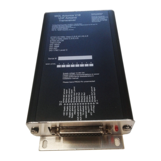
- Page 1 MGL Avionics V16 Aviation band transceiver A14/A16 Intercom system Digital audio and control Integration Manual Full document is available for download at www.mglavionics.co.za...
- Page 2 Table of Contents General............................3 Document history........................3 Applicability..........................3 Description..........................3 PTT connections.........................4 Setup............................4 RX Volume..........................4 V16 audio inputs and outputs.....................4 Installation limitations........................5 Single COM transceiver wiring....................5 Dual COM transceiver wiring......................6 Audio signal flow.........................6 Mixed operation...........................7 A14 vs A16..........................7 A16/V16 LED with digital audio link....................7...
- Page 3 Starting from firmware version V16 180222 (ddmmyy) and A14/A16 firmware release 7 (released on 18 February 2022) the A14 or A16 may be connected to one or two V16 transceivers in a fully digital manner eliminating the need for any audio wiring as well as PTT wiring between the devices.
- Page 4 Sidetone during transmit is available via the digital link. Note that this can be switched off in the V16 if so desired. Note further that the intercom itself has a side tone function that is configurable to bypass the radio completely if so desired.
- Page 5 Single COM transceiver wiring In this configuration the V16 microphone inputs are not used and should be left unconnected. PTT inputs on the V16 also also not used. Audio output of the V16 remains active but is not usually connected to anything.
- Page 6 Audio output of the V16 remains active but is not usually connected to anything. The position of the V16 in the wiring determines if it acts as COM1 or COM2. The V16 that has its RX line connected to the A16 TX line is always COM1.
- Page 7 It is possible to create a system with one A14/A16 intercom, one V16 using the digital link and a further COM or NAV/COM radio using a conventional analog audio connection. In this case wire the intercom and V16 as shown for a single V16. This V16 will appear as COM1 in the interface controller (Razor or EFIS).
Need help?
Do you have a question about the V16 and is the answer not in the manual?
Questions and answers