
Related Manuals for Ados T060E PN Series


Summary of Contents for Ados T060E PN Series
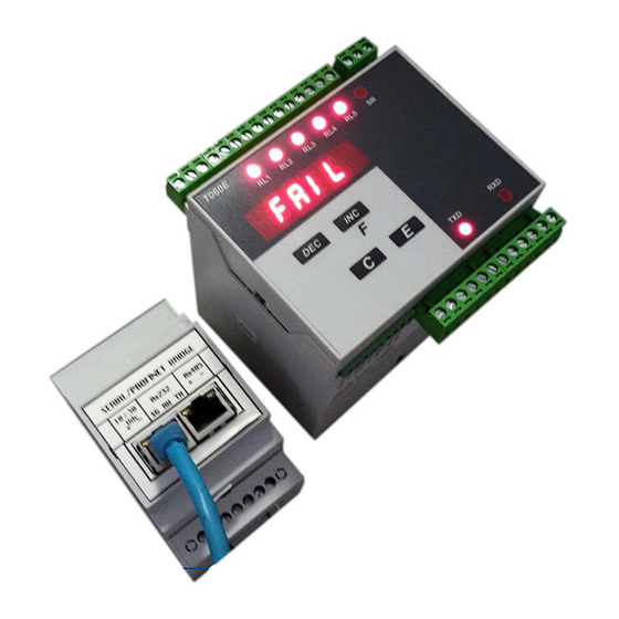
- Page 1 ELECTRONIC WEIGHING TRANSMITTER (PROFINET VERSION) T060Ex-PN User and installation manual 1710‐ PT060PNE Rev. 0 Page 1 of 57 ...
-
Page 2: Table Of Contents
Table of contents INTRODUCTION ............................4 Overview ................................4 Description ................................ 4 1.2.1 Options/ Versions ............................4 Use ..................................5 Description of labels ............................5 Operating specifications ............................ 6 ... - Page 3 5.4.12 Minimum alarm time of relay 1 ......................33 5.4.13 Minimum time to return to idle mode of relay 1 ..................33 5.4.14 Enabling of FAIL function for channel 1 ....................33 5.4.15 Enabling of FAIL function for channel 2 ....................
-
Page 4: Introduction
INTRODUCTION Overview This manual describes the installing, programming and troubleshooting procedures of weight transmitter, mod. T060E. The instruction manual must be stored properly and made available to all authorised staff. The instruction manual must be preserved until the equipment is put out of service. Additional copies can be requested to the Company’s assistance centre. For any clarifications or technical information, please contact the Company’s assistance centre. Please note that any instrument alterations will void the warranty, therefore, in case of issues, contact exclusively the Company’s assistance centres. The user of the equipment must comply with all safety standards applicable in the country where the device is used, ... -
Page 5: Use
THE FOLLOWING IS PROHIBITED: Open and apply changes and/or alterations to the equipment. If this clause is not respected, the warranty will be voided. Wet and/or immerse the instrument in any liquid. Expose it to strong magnetic and/or electric fields Use in areas subject to explosion hazard Open the equipment (it can be opened exclusively by authorised people) DANGER: Cut‐off power before performing any intervention on the instrument. Inspect the power supply cable on a regular basis to check if there are any damages, and if so, cut‐off power and replace it. The manufacturer declines any liability for damages caused to people or objects derived from an improper use of the device. Description of labels The labels affixed on T060E contain: indication of manufacturer identification of the instrument's model ... -
Page 6: Operating Specifications
Operating specifications From 9÷24 V ±10% (option) Power supply 110‐230~±10% Absorbed power 10W Operating temperature from –10 °C to +40 °C Storage temperature from –20 °C to +50 °C Relative humidity 95% non condensing Main display 6 digits, 11 mm LEDS Status signals 8 5 mm LEDS Keyboard 4 mechanical keys Load cell input power supply /114 mA (max 8 cells of 350 Ω in parallel) Load cell input 2 input power supply (optional) /114 mA (max 8 cells of 350 Ω in parallel) Input sensitivity 0.02 µV Linearity Temperature drift Converter’s resolution 24 bit Resolution of displayed weight 50000 div. Analogue signal From – 2 mV/V to + 3 mV/V Conversion speed 100 Hz Digital filter Selectable Serial ports ... -
Page 7: Instrument's Operation
INSTRUMENT’S OPERATION Turning on the instrument When the instrument is turned on, the following sequence of indications appears on the primary display, approx. every two seconds apart: 1. 0 (Revision of the installed software) When reaching this phase, the instrument becomes immediately operative and the weight value appears on the display. 1710‐ PT060PNE Rev. 0 Page 7 of 57 ... -
Page 8: Transmitter's Functions
Transmitter’s functions Instrument T060E is a weight transmitter with potential threshold relay management function. Therefore, it is not a traditional weighing instrument, since Gross, Net and Tare management functions are not available. Only ZERO corrections can be executed (through external inputs) with the purpose to recover zero derivatives or deviations relative to the weighing system. The onboard relays are managed as alarm relays, therefore they are always kept energized and are de‐energized in ... -
Page 9: Sum Value Function
2.2.2 Sum value function The T060Ei the double channel weighing version (D option) foresees the possibility to handle the sum value of the two channels. The value can be displayed both pushing and in association with one or more threshold relays alarms (see chapter 2.5). In case of systems with capacity or different unit measure, the operator mus realign the value to the same unit measure, deciding which of the two channels must be taken as reference channel. I.E.: Channel 1F.S. 10.00t and channel 2 1000kf F.S. considering channel 1 as reference channel(parameter PRIOR), we should return the channel 2 to a display in t. In order to get this the T060E with parameter MULTIP allows dividing or multiplying the channel value. In our example dividing by 1000 the channel 2 value is displayed as for channel 1 in t. According to different systems capacities, multiplying or dividing, it is possible to sum values with the same measure unit. 2.2.3 Management of the zero The external inputs can be used to reset potential zero derivatives or deviations relative to the weighing system. The ... -
Page 10: Signal Filtering
2.2.4 Signal filtering The instrument allows introducing filtering methods of the signal coming from load cells (FIR filters). This method is based on Digital Signal Processing (DSP) modes and allows handling at best, signals containing strong harmonic components (e.g. generated by mixers). During the configuration phase, it is possible to select three typical filters (with moving average) and 5 DSP filters. The former allow quicker response times but are less effective with regards to interferences, therefore they must be used when extremely quick weight variations must be detected. The latter allow mitigating interferences (since they boast a higher filtering effect) at the disadvantage of the response time to weight variations. In both cases, the higher is the filter’s number, the greater is the filtering effect and the response time to a weight variation. For example, the response to a step weight variation is shown in the chart below, based on the selected filter. The chart shows that filter FIR 1 boasts a response time of approx. 0.2 seconds, while filter FIR 5 boasts a response time of approx. 2.5 seconds. 1710‐ PT060PNE Rev. 0 Page 10 of 57 ... -
Page 11: Front Panel
Front panel 2 1 0 0 0 0 2.3.1 Display In normal operating conditions, the display indicates the weight values according to the following criteria: the irrelevant initial zeros are not displayed the “minus” sign (in case of negative weight values) is displayed in the first left digit If the negative weight value is of six digits (e.g. ‐324210), the first left digit will indicate the “minus” sign and the weight value, alternatively. If the negative weight value is of seven digits, the less significant five digits are displayed and the message starts flashing in order to indicate the presence of a non‐visible initial “1”. The first left digit will indicate the “minus” sign and the weight value, alternatively. The weight indication limits are: Lower limit: ‐ 20% of full scale upper limit: 120% of full scale If the weight is lower than the lower limit, the following indication is displayed: - - U L - - If the weight is greater than the upper limit, the following indication is displayed: - - O L - - ... -
Page 12: Led Signals
2.3.2 LED signals The meaning of the messages provided by the signal LEDS located on the instrument’s front panel is the following: RL1 ÷ RL5 The LED is on due to the triggering of the relative threshold The LED is on to notify the triggering of the safety signal The LED flashes to signal the transmission activity of serial port 1. The LED flashes to signal the receiving activity of serial port 1. 2.3.3 Key functions If the instrument is in operating mode, it allows commuting the reading (if the instrument foresees the optional second channel) to display the weight value of the second channel or total value (channel 1 + channel 2). ... -
Page 13: Management Of Relays
Management of relays The basic instrument is equipped with five relays that can be configured as required. A generally open contact (NA) not under voltage is available for each relay. The relays’ operation is linked to the conditions defined in the configuration phase. The relays’ commutation takes place when the threshold value set in the configuration phase (SET # parameter) is reached and remains in this condition for a timeframe equal to or exceeding the alarm minimum time (DAL # parameter). It is restored in normal conditions when the weight value is dropped below the value determined by the ... -
Page 14: Installation
INSTALLATION Receiving the material Before signing the transport document, make sure there are no damages to the equipment caused during transport and if so, notify the carrier. In addition to the instrument, the following must be present: 1 series of female flying terminals for connecting the power supply and input and output signals 1 copy of the instruction manual 1 copy of the instrument’s testing report (check that the serial number appearing in the relative label corresponds to the serial number indicated on the testing sheet). MODEL T060E1 INPUT 100‐240 V ~ 10 W 50 / 60 Hz S.N. 20160234 Each device features the required information for proper identification: model and serial number. This data, together with the software version, must be indicated when requesting information. Assembling the instrument WARNING ... -
Page 15: Connections
Connections All instrument’s connections are carried out on the side of the instrument. Rear panel A label containing screen‐printed indications to facilitate the operator in carrying out cabling operations is affixed on the sides of the instrument near terminals. SIDE B SIDE A Power supply tag Before connecting the equipment to a power source, make sure that the selected value on the label corresponds to the foreseen voltage. If the foreseen values differs from the voltage indicated on the tag, do not connect the equipment and contact exclusively a company’s assistance centre to change the version if needed. 1710‐ PT060PNE Rev. 0 Page 15 of 57 ... -
Page 16: Connection To Power Supply (Side B)
Connection to power supply (side B) 10 11 12 13 14 15 16 17 18 100-240VAC 24VAC 48VAC 24VDC 3.6.1 Version 110÷230V~ 24-48V~ INDICATION FUNCTION TERMINAL Neutral Line Ground Connect the instrument’s safety ground terminal to the system’s ground bar through flexible cable. 3.6.2 Version 12÷24V ... -
Page 17: Connection Of Load Cells (Side A)
Connection of load cells (side A) The cable coming from the load cells or junction box must be connected to the terminals located on the rear of the instrument and called LOAD CELL 1. Connection between the load cell and the instrument must be carried out with a shielded cable. The cable’s shield must be connected to the ground. Connection must take place respecting the colour code indicated on the load cells. T060 foresees the standard connection of 6‐wire load cells. In case of connection of 4‐wire load cells, connect the reference wires to the relative polarities of the power supply cables. MAKE SURE THE CONNECTION CABLE BETWEEN LOAD CELLS AND INSTRUMENT IS DUCTED IN TROUGHS SEPARATE ... - Page 18 In case of 4‐wire connection, short‐circuit the terminals – Excitation with ‐ Reference and + Excitation with + Reference. CONNECTION WITH 4‐WIRE LOAD CELLS CONNECTION WITH 6‐WIRE LOAD CELLS 1710‐ PT060PNE Rev. 0 Page 18 of 57 ...
-
Page 19: Connection Of Load Cells 2 Input
3.7.2 Connection of load cells 2 input T060E foresees an optional second load cells input. The considerations made for the main channel also apply for the optional input channel. 28 29 30 32 33 LOAD CELL 2 LOAD CELL 1 OPTO OPTO ANALOG SERIAL SERIAL OUTPUT OUT 2 OUT 1 INDICATION FUNCTION TERMINAL + Excitation ... -
Page 20: Wiring Example (Single Weighing System)
3.7.3 Wiring example (single weighing system) In the case of plant consists of a single weighing system with one or more cells connected in parallel the wiring must be made on channel 1 (see diagram as an example) Example of a system consisting of a single weighing system with only two load cells in parallel 1710‐ PT060PNE Rev. 0 Page 20 of 57 ... -
Page 21: Wiring Example (Double Weighing System)
3.7.4 Wiring example (double weighing system) In the case of plant consists of a double weighing system with one or more cells connected in parallel the wiring must be made like a diagram as an example Example of a system consisting of a double weighing system with only one load cells for each system 1710‐ PT060PNE Rev. 0 Page 21 of 57 ... -
Page 22: Connection Of Serial Lines (Side A)
Connection of serial lines (side A) T060E is equipped with 2 serial lines. Output 1, opto‐isolated and configurable as RS485 or RS232 and output 2 foreseen for the RS485 interface. Output 2 is disabled in case of PROFINET option. In compliance with EIA standards, the cable’s length must not exceed 15 metres in case of RS232 and 1000 metres in case of RS485. RS232 It is suggested to use a shielded cable and connect the shield on one side only. RS485 Use a twisted shielded cable (1 couple) suitable for serial communications. Use separate troughs from those of power lines, where possible. 28 29 30 32 33 LOAD CELL 2 LOAD CELL 1 OPTO OPTO ANALOG SERIAL SERIAL OUTPUT OUT 2 OUT 1 ... -
Page 23: Digital Inputs (Side B)
Digital inputs (side B) In its standard version, the instrument is equipped with two (2) opto‐isolated digital inputs. Use separate troughs from those of power lines, where possible. Activation takes place by connecting the common terminal and the input terminal. Closing must take place with potential free contact not under voltage (the inputs are self‐powered internally by the T060E). 10 11 12 13 14 15 16 17 18 100-240VAC 24VAC 48VAC 24VDC INDICATION FUNCTION TERMINAL INP 1 Tare channel 1 INP 2 Tare channel 2 C INP Common 1710‐ PT060PNE Rev. 0 Page 23 of 57 ... -
Page 24: Connection Of Relay Outputs (Side B)
3.10 Connection of relay outputs (side B) In its standard version, the instrument is equipped with five (5) SPST relay outputs. For each relay, the user boasts a generally open contact (NA) not under voltage. The capacity of the contacts is 0.5A to 48 V on resistive load. If the relay contacts are used to control relay coils, arc suppression devices parallel to the contact must be foreseen. Use separate troughs from those of power lines, where possible. The relays are managed as alarm relays, therefore they are always kept energized and are de‐energized in case of alarm. 10 11 12 13 14 15 16 17 18 100-240VAC 24VAC 48VAC 24VDC INDICATION FUNCTION TERMINAL OUT 1 Relay 1‐ NO OUT 1 Relay 1‐ C ... -
Page 25: 3.11 Optional Analogue Output
3.11 Optional analogue output T060E is equipped with an analogue output (active type) that can be configured either as analogue output under voltage or as analogue output under current. It is recommended to use a shielded cable and if required, the use of separate troughs in order not to prejudice the proper use of the equipment and optimal performances. The shield must be connected on one side only. 28 29 30 32 33 LOAD CELL 2 LOAD CELL 1 OPTO OPTO ANALOG SERIAL SERIAL OUTPUT OUT 2 OUT 1 INDICATION FUNCTION TERMINAL VOUT Output under voltage ... -
Page 26: 3.12 Profinet Output
3.12 PROFINET output 1 7 PIN FUNCTION 1 + 10 ÷ 30 Vdc (positive) POWER SUPPLY 2 Massa (negative) 3 GND 4 RX Rs232 5 TX 6 + (positive) Rs485 7 ‐ (negative) 1710‐ PT060PNE Rev. 0 Page 26 of 57 ... -
Page 27: Maintenance On The Instrument
MAINTENANCE ON THE INSTRUMENT Preventive maintenance The instrument does not require particular preventive maintenance operations. For safety purposes, check the connections of the safety wires on a regular basis, with a visual inspection. Corrective maintenance Each corrective maintenance operation concerning instrument’s faults must be carried out exclusively at ADOS’ laboratories or anyhow, by ADOS staff. ANY INSTRUMENT’S ALTERATION WILL VOID THE WARRANTY. 1710‐ PT060PNE Rev. 0 Page 27 of 57 ... -
Page 28: Management Of The Instrument
MANAGEMENT OF THE INSTRUMENT Introduction T060E transmitter is a programmable instrument able to carry out a series of functions that may be adapted and/or personalized by the user, intended for multiple applications. These functions can be modified through the configuration parameters. Therefore, the instrument must be configured according to the specific application, before being used. All configuration parameters are stored in a non‐volatile memory. The status of the parameter memory is checked when turning on the instrument: in case of negative outcome, the instrument is automatically re‐initialized to the basic configuration and must be re‐configured and re‐calibrated. Operational sequence After performing all connections, the logic operational sequence foresees: The configuration of operational parameters The system’s calibration Selection of the management functions The following management functions are foreseen: CONFIGURATION S et‐up of general parameters CALIBRATION Weight calibration INSTRUMENT TEST Management of test functions To access the instrument’s management mode, press key . The instrument is ready to configure the parameters and displays the following message: By pressing key , the management level is commuted and the following messages appear: Press to confirm the selection, while press key to cancel the management request and return ... -
Page 29: Configuration Of Operational Parameters
Configuration of operational parameters 5.4.1 Selection of operational parameters By accessing the configuration mode from the selection menu of configuration levels, the instrument is ready to configure the first parameter and displays the following message: Press key to select all configurable parameters in sequence (once the last one is reached, the system returns to the first one automatically). ... -
Page 30: Editing Of The Value Of Operational Parameters
5.4.2 Editing of the value of operational parameters By accessing the configuration mode from the parameter selection menu, the instrument shows the parameter's value or code on the main display. The display flashes to indicate that the instrument is ready to accept the edited parameter’s value. Press key to increase the value of the selected parameter (once the maximum value is reached, the system returns automatically to 0). If the data shown is a weight (e.g. a relay threshold), the increase takes place according to the configured sensitivity. By keeping key pressed, the increase gradient is automatically increased up to maximum 128 times the basic increase value. Press key to decrease the value of the selected parameter (once zero is reached, the system returns automatically to the maximum value). ... -
Page 31: Setting The Load Cells' Signal
5.4.3 Setting the load cells’ signal It is the sensitivity value of the load cell. The maximum allowed signal is 3.5 mV/V. 5.4.4 Setting the weighing system capacity It is the capacity of the weighing system. The maximum capacity consists of 100000 divisions. 5.4.5 Setting the system resolution The value can be selected within the range from 50 to 0.001 divisions. The system resolution is given by the ratio between capacity and resolution. See also point 2.2.1 5.4.6 Average settings This parameter is used for the digital filtering of the weight signal, ... -
Page 32: Reference Channe Selection (Only With Instrument With Double Channel)
5.4.7 Reference channe selection (only with instrument with double channel) This parameter define the reference channel CH 1 CH 2 5.4.8 Scale factor selection ((only with instrument with double channel) This parameter define the scale factor selection. Value multiplying for 10 Value multiplying for 100 1000 Value multiplying for 1000 10000 Value multiplying for 10000 10000 Value dividing for 10000 1000 Value dividing for 1000 Value dividing for 100 Value dividing for 10 5.4.9... -
Page 33: Threshold Value Of Relay 1
5.4.10 Threshold value of relay 1 This parameter defines the threshold value to assign to relay 1. See chapter 2.5. 5.4.11 Hysteresis value of relay 1 This parameter defines the hysteresis value assigned to relay 1. See chapter 2.5. 5.4.12 Minimum alarm time of relay 1 This parameter defines the minimum time to trigger the alarm of relay 1. See chapter 2.5. 5.4.13 Minimum time to return to idle mode of relay 1 This parameter defines the minimum time for relay 1 to ... -
Page 34: Function Of Serial Port 1
5.4.16 Function of serial port 1 Serial port excluded. Serial port with constant string transmission. Serial port with logic HALF DUPLEX protocol. The instrument responds as BIDIR slave. In case of multi‐point operating mode, the data structure foresees the additional ID RS485 address field. MODBUS Serial port enabled to MODBUS‐RTU protocol 5.4.17 Physical interface of serial port 1 RS-485 Physical interface RS485 on two balanced wires RS-232 Physical interface RS232 (point‐point connections) ... -
Page 35: 5.4.18 Data Transmitted On Serial Port 1 In Continuous Mode
5.4.18 Data transmitted on serial port 1 in continuous mode CELL 1 Weight value relative to channel 1 CELL 2 Weight value relative to channel 2 TOTAL Weight value relative to sum (channel 1 + channel 2) 5.4.19 Baud rate of serial port 1 1200 2400 4800 9600 19200 38400 ... -
Page 36: 5.4.21 Analogue Output
5.4.21 Analogue output The configuration of the analogue output foresees 3 steps: Definition of the type of output required. AN VAL Definition of the operating mode of the analogue output. Definition of the full scale to associate to the analogue output. 5.4.22 Definition of the type of analogue output A 4-20 Output under 4‐20 mA current. A 0-20 Output under 0‐20 mA current. U 0-10 Output under 0‐10 V voltage. U10-10 Output under 10‐10 V voltage. 5.4.23 Function of the analogue output ... -
Page 37: 5.4.24 Full Scale Of The Analogue Output
5.4.24 Full scale of the analogue output It defines to which weight value, the maximum value of the analogue output must correspond. The change of the analogue function cause the clearance of the analog output data (AN FS). 1710‐ PT060PNE Rev. 0 Page 37 of 57 ... -
Page 38: Calibration
Calibration 5.5.1 Theoretical calibration procedure In general, the best calibration method consists in applying a known weight (sample weight) on the weighing system. This method is not always possible to execute, when weights boasting a too high mass are used. Other systems implemented, in case of large size tanks, consist of: use of tested litre counters or filling with a specific water quantity. In case of tanks of large capacity, when sufficient calibration weights are not available or geometries do not allow loading large masses, calibration is carried with substitute weights: 1. The tank is loaded with known weight masses 2. The value read by the indicator is recorded 3. The known weights are removed 4. The tank is loaded with the material (or water, or material used by the system) until reaching the weight value indicated in point 1 5. Re‐load the same weights previously loaded in point 1 6. The value read by the indicator is recorded 7. The known weights are removed once again 8. The tank is loaded with the material until reaching the weight value indicated in point 3 9. Repeat steps 1 and 2 until reaching the nominal load, then correct the calibration curve (SPAN) if needed. During the calibration phase, by using known masses, it is possible to check the interferences and errors caused by the application of the load on mechanical parts or load cells. After carrying out the configuration steps of the THEORETICAL calibration (setting of the nominal capacity of the load cells system and relative sensitivity), it is a good practice to check the system’s calibration. Calibration consists of the following steps: Tare with permanent storage Calibration of the zero value Calibration of full scale ... -
Page 39: Permanent Tare
5.5.2 Permanent tare To access the calibration menu, you must enter the instrument’s management menu by selecting the following function: Press Key Press key or to cancel the operation. Press Key 1710‐ PT060PNE Rev. 0 Page 39 of 57 ... -
Page 40: Zero Calibration
5.5.3 Zero calibration Before calibrating the zero, make sure the weighing system is completely empty and the reading is stable. Zero calibration foresees the resetting of the tare value, therefore make sure the structure is complete. To access the calibration menu, you must enter the instrument’s management menu by selecting the following function: Press Key Press key or to cancel the operation. The instrument is ready to receive the confirmation command. By pressing key , the instrument performs the calibration and displays message: The operation can be repeated a few times. Zero calibration is the same also for channel 2. 1710‐ PT060PNE Rev. 0 Page 40 of 57 ... -
Page 41: Span Calibration
5.5.4 Span calibration Before calibrating the span, load the weighing system with the known weight exceeding the full scale by 12.5% and wait until the reading stabilizes. The more the known weight is closer to the full scale value, the more accurate the full scale calibration will be. The system is ready to carry out the calibration with a known weight corresponding to the value of the weight currently on the scale. The operator can modify the procedure by setting directly the known weight value, using keys to increase or decrease the displayed value. To access the calibration menu, you must enter the instrument’s management menu by selecting the following function: Press Key Press key or ... -
Page 42: Linearization
5.5.5 Linearization The system foresees the option to linearize the calibration curve through interpolations in four points. Linearization will be effective only if the error can be repeated. To access the calibration menu, you must enter the instrument’s management menu by selecting the following function: Press Key Press key or to cancel the operation. Press key or to cancel the operation. Press key or to cancel the operation. By pressing key the instrument goes in calibration mode and the display shows the calibration value and function in progress, alternatively (LIN 1). The operator can modify the procedure using keys or to increase or decrease the displayed value. Once the required weight value is input, by pressing key ... -
Page 43: Analogue Output Adjustment
5.5.6 Analogue output adjustment The adjustment functions of the analogue output are the same for output under voltage and under current. The adjustment of the analogue output foresees 3 steps: 1. Setting of the analogue scale (FULL SCALE D/A) 2. Zero alignment (ZERO ADJUSTMENT D/A) 3. Full scale alignment (SPAN ADJUSTMENT D/A) The first step defines to which weight value, the maximum value of the analogue output must correspond. For example, the weighing full scale could be 5000, but the maximum value of the analogue output could be set to 3000. This way, for weight values from 0 to 3000, the analogue output will range from 0 to 10 V (or from 4 to 20 mA); for higher values, the output will remain set to the maximum value. Similarly, for negative weight values, the analogue output will remain set to the minimum value. The second phase consists in aligning the analogue output so that zero (minimum possible value) is exactly at 0 V or at 4 mA. The third phase consists in aligning the analogue output so that the span (maximum possible value) is exactly at 10 V or at 20 mA. The ajustment procedure must be viewed on the receiving system of the transmitted analogue signal. -
Page 44: Zero Adjustment D/A
5.5.7 Zero adjustment D/A To continue, connect a digital multimeter to the terminals of the instrument's analogue output, paying attention to make the proper connections. Set‐up the multimeter to measure voltage or current, according to the type of output of T060E. To access the calibration menu, you must enter the instrument’s management menu by selecting the following function: Press Key Press key until visualizing the parameter: By pressing key , the instrument begins the zero adjustment procedure of the analogue output. A numeric value, proportional to the output value under voltage or current read on the multimeter, is visualized in this phase. Press keys to modify this value until 0V or 4 mA are exactly read on the multimeter. Press to confirm the displayed value and press to cancel. 1710‐ PT060PNE Rev. 0 Page 44 of 57 ... -
Page 45: Full Scale Adjustment D/A
5.5.8 Full scale adjustment D/A To continue, connect a digital multimeter to the terminals of the instrument's analogue output, paying attention to make the proper connections. Set‐up the multimeter to measure voltage or current, according to the type of output of T060E. To access the calibration menu, you must enter the instrument’s management menu by selecting the following function: Press Key Press key until visualizing the parameter: By pressing key , the instrument begins the zero adjustment procedure of the analogue output. A numeric value, proportional to the output value under voltage or current read on the multimeter, is visualized in this phase. Press keys to modify this value until 10 V or 20 mA are exactly read on the multimeter. Press to confirm the displayed value and press to cancel. 1710‐ PT060PNE Rev. 0 Page 45 of 57 ... -
Page 46: Instrument Test
Instrument test This function allows the user checking the optimal operation of some sections of the instrument, such as: Proper connection of relay outputs Optimal operation of digital inputs Optimal operation of the analogue output The signal generated by load cells 5.6.1 Testing relay outputs and digital inputs To access the test menu, you must enter the instrument’s management menu by selecting the following function: Press Key Press to check the relay connections and optimal operation of the inputs; the instrument displays two messages: Test relay outputs Test inputs Press to energize each relay in sequence and individually while, in order to test inputs, close the required input and test the actual closing by reading the following message: Input 1 closing Press to cancel the test. 1710‐ PT060PNE Rev. 0 Page 46 of 57 ... -
Page 47: Testing The Analogue Output
5.6.2 Testing the analogue output To access the test menu, you must enter the instrument’s management menu by selecting the following function: Press keys and until selecting message: Press key to confirm the selection; the instrument displays two messages, alternatively: By pressing keys , the analogue output is increased or decreased by 1/10 full scale until reaching the full scale or zero, then it returns to zero or full scale. Press to cancel the test. 1710‐ PT060PNE Rev. 0 Page 47 of 57 ... -
Page 48: Testing Load Cell Inputs
5.6.3 Testing load cell inputs To access the test menu, you must enter the instrument’s management menu by selecting the following function: Press keys and until selecting message: Test input of cell 1 Test input of cell 2 Press key to confirm the selection; the instrument displays two messages, alternatively: Signal coming from load cells of channel 1 (value expressed in 0. 4 mV/V. The test of channel 2 follows the same procedure. Press to cancel the test. 1710‐ PT060PNE Rev. 0 Page 48 of 57 ... -
Page 49: Serial Protocol Communication
Transmission to repeater (Repeat) The instrument transmits a string to a serial repeater model CS089. The transmission parameters of both lines are : 8 bit ‐ No Parity ‐ 1 Stop When using ADOS protocol the point to point or multidrop connection is determined by the value of the configuration parameter “address 485”: if the parameter is 0 the connection is point to point, otherwise it is multidrop. The modality is activated independently from the physical configuration of the board, therefore it is possible to operate with addressed frames on the physical line RS232. The data frames are the same in both configuration, with the only addition of the address field (two characters from “01” to “32”) in reception and in transmission. 1710‐ PT060PNE ... -
Page 50: String Format In Continuous Mode
String format in continuous mode The ASCII string transmitted is the same for both ports. ID485 = 0 (lenght 16 characters) 1° character <STX> (Hex 02) Start of text 2° character [SIGN] SPACE> (Hex 20) if the weight value is positive <‐> (Hex 2D) if the weight value is negative 3° character [WEIGHT 1] from <0> (Hex 30) to <9> (Hex 39) to indicate the numeric weight value with an eventual decimal point <.> (Hex 2E) or <SPACE> (Hex 20) to cancel the insignificant zeros in front of the number 4° character [WEIGHT 2] as above 5° character [WEIGHT 3] as above 6° character [WEIGHT 4] as above 7° character [PESO 5] as above 8° character [WEIGHT 6] as above 9° character [WEIGHT 7] as above 10° character [RELAY] 1 character for alarm relay status. Hexadecimal coded character (*) ... - Page 51 ID485 > 0 (lenght 18 characters) 1° character [STX] (Hex 02) Start of text 2° character [ID485 H] from <0> (Hex 30) to <9> (Hex 39) to indicate the tens of the set ID485 value 3° character [ID485 L] from <0> (Hex 30) to <9> (Hex 39) to indicate the units of the set ID485 value 4° character [SIGN] SPACE> (Hex 20) if the weight value is positive <‐> (Hex 2D) if the weight value is negative 5° character [WEIGHT 1] from <0> (Hex 30) to <9> (Hex 39) to indicate the numeric weight value with an eventual decimal point <.> (Hex 2E) or <SPACE> (Hex 20) to cancel the insignificant zeros in front of the number 6° character [WEIGHT 2] as above 7° character [WEIGHT 3] as above 8° character [WEIGHT 4] as above 9° character [PESO 5] as above 10° character [WEIGHT 6] as above 11° character [WEIGHT 7] as above 12° character [RELAY] 1 character for alarm relay status. Hexadecimal coded character (*) ...
-
Page 52: Calculation Of The Checksum
6.2.1 Calculation of the checksum The two ASCII characters which identify the checksum must be calculated in the following way: Calcolate the XO R binary of all the characters from the 1° to the 12° included in the case of strings of 16 characters (ID485 = 0) or to the 14° included in the case of strings of 18 characters (ID485 > 0). Separate the XOR values obtained into a high area (first 4 bit) and a low area (last 4 bit) Code the high area according to the ASCII hex table, which will become the character written in position [CHK 1] (13° character in the case of a string of 16 characters, 15° in the case of a string of 18 characters). For example the binary value 5 (0101) will become character <5> (Hex 35), or the binary value B (1011) will become character capital <B> (Hex 42). Code the lower area according to the ASCII hex table, which will become the character written in position [CHK 2] (14° character in the case of a string of 16 characters, 16° in the case of a string of 18 characters). ... -
Page 53: Bi-Directional Modality With Modbus Protocol
Bi-directional modality with MODBUS protocol The RTU version of MODBUS is used. Received and transmitted frame structure. General frame structure is as follows: ADRESS FUNCTION DATA CHECK 8 bits 8 bits N x 8 bits 2 x 8 bits ADDRESS FUNCTION DATA CHECK 8 bits 8 bits N x 8 bits 2 x 8 bits ADDRESS 8 bit defining the slave address and ranging from 1 to 32 FUNCTION 8 bit defining the required function. The functions supported by T060E are the following Code 03 Read Holding Registers Code 05 Force Single Coil DATA ... -
Page 54: T060E Registers List
Function 05 ‐ Force Single Coil Allows the host to force a single coil. In T060E the command is used to issue a TARE or POF reset command. The below is a valid example: ADDR FUNC COIL COIL DATA DATA CHECK # # VALUE VALUE HI LOW HI LOW 01 05 00 00 FF 00 8C 3A The normal response is to retransmit the query message: ADDR FUNC COIL COIL DATA DATA ... -
Page 55: Status Word Coding
6.4.2 Status word coding 15 14 13 12 11 10 3 2 IN2 IN1 SR R5 R4 R3 FAIL2 OL1 FAIL1 POF Power On Flag. Indicates a return of power supply to the transmitter Flag is set to 1 by T060E and can be resetted to 0 by host by forcing Coil #0 S If = 1 indicates configuration in progress or in test R1 ... -
Page 56: Profinet Protocol
PROFINET protocol 6.5.1 Data from T060E weight transmitter (INPUT DATA AREA) Register Funzione 0x0000 Status word 0x0001 Gross weight channel 1 (MSB) 0x0002 Gross weight channel 1 (LSB) 0x0003 Gross weight channel 2 (MSB) 0x0004 Gross weight channel 2 (LSB) 0x0005 Total gross (CH1+CH2) (MSB) 0x0006 Total gross (CH1+CH2) (LSB) 0x0007 Net weight channel 1 (MSB) 0x0008 Net weight channel 1 (LSB) 0x0009 Net weight channel 2 (MSB) 0x000A Net weight channel 2 (LSB) 0x000B Total net ((CH1‐Tara)+(CH2‐Tare)) (MSB) 0x000C Total net ((CH1‐Tara)+(CH2‐Tare)) (LSB) 6.5.2 Status word coding 15 ... - Page 57 ADOS s.r.l. Cap.soc. € 36.400,00 int.ver. Via Lazio, 25 R.E.A. 851258 20090 Buccinasco MILANO - Italy C.F./P.IVA n 01070150154 Tel +39-2-45700120 http:\\www.ados.it Fax +39-2-48840833 Email: info@ados.it EU Declaration of conformità (DoC) The Company: ADOS s.r.l Via Lazio, 25...
Need help?
Do you have a question about the T060E PN Series and is the answer not in the manual?
Questions and answers