Table of Contents
Advertisement
Instruction Manual
Table of Contents
● Safety considerations ........................... 1
● Caution during use ............................... 2
● Installation instructions ....................... 3
● Product overview ................................. 4
● Order of the operation .......................... 7
● SETUP group ........................................ 9
● Setting the timer ................................... 13
● Setting the program ............................. 15
● Error display ......................................... 18
● When operating safety devices ........... 18
● Factory defaults .................................... 19
● About the maintenance ....................... 19
● Trouble shooting .................................. 20
● Specifications ....................................... 21
● FAQs ...................................................... 22
● Contact information ............................. 26
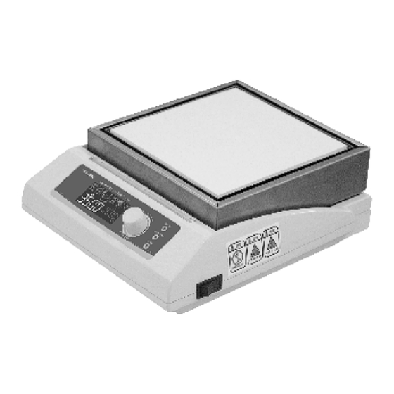
Thank you for your selecting Digital Hotplate NDK Series.
For your safety & life span of the product, please read this "instruction manual" fully
before using and keep these instructions.
After reading this instruction, keep it in a place where you can see it at any time.
Make sure that this instruction with the product should be given to the following
users for safe use.
Digital Hotplate
................. 11
........ 17
CORPORATION
1-4601-31-90,-91、1-4601-32-90,-91
NDK-1A-I, NDK-1A-F
Advertisement
Table of Contents

Related Manuals for AS ONE NDK-1A-I

Summary of Contents for AS ONE NDK-1A-I
-
Page 1: Table Of Contents
1-4601-31-90,-91、1-4601-32-90,-91 Digital Hotplate Instruction Manual Table of Contents ● Safety considerations ......1 NDK-1A-I, NDK-1A-F ● Caution during use ....... 2 ● Installation instructions ....... 3 NDK-2A-I, NDK-2A-F ● Product overview ......... 4 ● Order of the operation ......7 ●... -
Page 2: Safety Considerations
➊ -|Transparent setting guide|- Safety considerations Please read "Safety considerations" before using and use the product correctly. The suggestions below have possible to connect the serious result. Please keep these instructions for safety. Warning mark & meaning Danger Danger of death or serious injury is near at hand with wrong handling. -
Page 3: Caution During Use
➊ -|Transparent setting guide|- Caution during use When you receive the product, inspect it to check any problems from the delivery or damages. If the product is damaged or does not work as specifications, contact the purchasing place. ◆ Caution for shipping When shipping the product after opening it, use the packaging materials used for the original packaging. -
Page 4: Installation Instructions
➊ -|Transparent setting guide|- Installation instructions ● This product works well in rated power supply and frequency. Before supplying the power, be sure to check the rated power and frequency. ● Use the included power cable. Also, do not use this with other devices. ●... -
Page 5: Product Overview
➊ -|Transparent setting guide|- Product overview ■ Unit Description The front side ◆ 1. LED bar: LED lights up or blinks based on the operating status (normal / error) and the temperature of the top plate when the operation stops. 2. - Page 6 ➊ -|Transparent setting guide|- Product overview ◆ The back side 1. Power input terminal : External power cable (approx. 1.8m) 2. Fuse holder : Fuse specifications (250V 7A Ø6.4×30mm) 3. Alarm output terminal : It is a connector to connect alarm output (relay contacts) wires. 4.
-
Page 7: Ndk-2A-I, Ndk-2A-F
➊ -|Transparent setting guide|- Product overview ■ Dimensions (Unit: mm) NDK-1A-I, NDK-1A-F ◆ NDK-2A-I, NDK-2A-F ◆ - 6 -... -
Page 8: Order Of The Operation
Please set the power switch at ON in the back side of the body. After the power is on, the LCD indication part shows [ AS-1 ] and model name (e.g., [ ND-1 ] for NDK-1A-I/F) for 5 seconds and then shows the state of stop operation. 3. Setting the set temperature (SV) The set temperature (SV) flashes when the operation stops. - Page 9 ➊ -|Transparent setting guide|- Order of the operation 5. All parameters PROGRAM press once It is activated when setting program Setting program [ PRG ] in the SETUP group is set to ON . See Setting the program SETUP press once It enter the SETUP group.
-
Page 10: Setup Group
➊ -|Transparent setting guide|- SETUP group SETUP ※ Press the key once during the operation, checking the parameter value of the SETUP group is only available. (The setting cannot be changed.) STOP SETUP SETUP mode ※ Press the key once to return to the RUN mode. ※... - Page 11 ➊ -|Transparent setting guide|- SETUP group Sampling Setting range: 5, 10, 15, 30 sec/1, 2, 5, 10, 15, 30, 60 min Sampling time ※ It appears when sampling [ SP ] is set to ON . Setting range: 0.0~100.0℃ Proportional ※ON/OFF control: Set proportional band [ P ] to 00)0 band ※PID control: Set proportional band [ P ] over 00)1 .
-
Page 12: Setup Group Function
➊ -|Transparent setting guide|- SETUP group function 1. Alarm [ ALM ] You can use the alarm function. Alarm[ ALM ] is set to ON to use, and when the alarm is not used, set to OFF . When set to ON , appears on the icon display part. - Page 13 5 seconds. (Up to 7,700 values) You can check the saved data using the comprehensive device management program (DAQMaster for AS ONE) by connecting the main unit and PC. For more information, see the DAQMaster for AS ONE user manual.
-
Page 14: Setting The Timer
➊ -|Transparent setting guide|- Setting the timer You can set the time for start, progress and end of control output. Set the timer mode in timer [ ST-T ]of the SETUP group. when the operation stops, press the to set the time in the timer mode. MODE 1. - Page 15 ➊ -|Transparent setting guide|- Setting the timer 2. Setting the time mode In the STOP mode, press the key once, turning the JOG switch to set time of each timer MODE mode in the timer [ ST-T ] of SETUP group. ※...
-
Page 16: Setting The Program
➊ -|Transparent setting guide|- Setting the program You can set the conditions for temperature control as a program. Select one program out of 9 programs. One program should consist of at least 2 to 8 steps. Each step consists of the target value [ SV □], run time [ TIM □],and wait time [ WAT □]. Temperature control is executed based on the target value, run time and wait time. - Page 17 ➊ -|Transparent setting guide|- Setting the program ※ Program setting [ PRG ] of SETUP group is set to On to set a program. 2. Program setting ※ The program setting is unavailable in the RUN mode. PROGRAM ※ Press the key once to return to the RUN mode at any parameter.
-
Page 18: Other Functions
➊ -|Transparent setting guide|- Other functions 1. Key lock ( key 3 sec.) SETUP Lock the front keys and JOG switch, preventing unintentional changes of setting value. SETUP In the stop mode, press the key for more than 3 seconds to set / release the key lock. LOCK setting: The front keys and JOG switch cannot be used. -
Page 19: Error Display
➊ -|Transparent setting guide|- Error display If an error occurs, a corresponding message and alarm are generated. (It is not related to the operation sound [ BUZ ] of the SETUP group.) Display Description If the PV is higher than the display range, it flashes every 0.5 seconds on the PV indication part. -
Page 20: Factory Defaults
➊ -|Transparent setting guide|- Factory defaults Parameter Initial value Parameter Initial value Parameter Initial value 0040 0010 AL-H 30)0 AL-L 00)0 00@0 REST 05)0 ST-T 00#0 About the maintenance Please unplug first for maintenance and repair. ◆ Daily maintenance ● Please clean the alien material on the body with soft and dry towel. ●... -
Page 21: Trouble Shooting
● Check the characteristics of the controlled subjects based on this product's performance. It cannot be communicated ● See [DAQMaster for AS ONE user manual] in the additional CD-ROM. well. If it cannot be repaired with the guides above, please stop the using, unplug the power, and contact the purchasing place. -
Page 22: Specifications
➊ -|Transparent setting guide|- Specifications Model NDK-1A-I NDK-1A-F NDK-2A-I NDK-2A-F Power supply 220VACᜠ 50/60Hz Current consumption 3.1A 4.6A Heater capacity 680W 1000W The appearance size (W×L×H) 240×280×90mm 320×360×90mm The top plate size (W×L) 170×170mm 250×250mm Material of the top plate... -
Page 23: Faqs
➊ -|Transparent setting guide|- FAQs Q. I want to set the temperature faster. Is it just a way to turn the JOG switch? A. You can move the set value via the MODE key. Q. Please release the drawings of the heater. A. - Page 24 ➊ -|Transparent setting guide|- - 23 -...
- Page 25 ➊ -|Transparent setting guide|- - 24 -...
- Page 26 ➊ -|Transparent setting guide|- - 25 -...
-
Page 27: Contact Information
➊ -|Transparent setting guide|- Contact information Corporate Headquarters: ASONE Corporation 2-1-27, Edobori, Nishi-ku Osaka 550-8527 Japan Tel: 81-6-6447 8905 Fax: 81-6-6447 8911 E-mail: asoneint@so.as-1.co.jp CORPORATION ■ ABOUT REPAIR For repair inquiries, please contact the distributer where you purchased the product. ※The specification and dimensions can be changed without notice in order to improve the product.
Need help?
Do you have a question about the NDK-1A-I and is the answer not in the manual?
Questions and answers