Advertisement
Available languages
Available languages
Quick Links
EN
INSTRUCTION
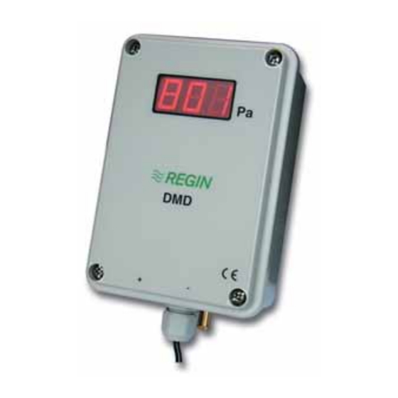
DMD
IN20008 REV. B, 2019-10-03
C C a a u u t t i i o o n n ! ! Read and understand the instruction before using the product.
C C a a u u t t i i o o n n ! ! Ensure that the installation complies with local safety
regulations.
C C a a u u t t i i o o n n ! ! Before installation or maintenance, the power supply should first
be disconnected. Installation or maintenance of this unit should only be
carried out by qualified personnel. The manufacturer is not responsible
for any eventual damage or injury caused by inadequate skills during instal-
lation, or through removal of or deactivation of any security devices.
Technical Data
Supply voltage
24 V AC/DC (21...27 V AC/DC)
Power consumption
5 VA
Load impedance, 0...10 V
> 2 kΩ
Load impedance, 4...20 mA
< 500 Ω
Protection class
IP54
Ambient humidity
Max. 90 % RH (non-condensing)
Ambient temperature
0...50 °C
Storage temperature
-40...+50 °C
Media temperature
0...70 °C
Max. overload pressure
20 kPa
Mounting
Wall
Media
Air and non-corrosive gases
Measuring range, pressure
0...100 / 0...300 / 0...500 / 0...999 Pa
Output signal, pressure
0...10 V DC / 4...20 mA
Temperature dependency,
± 0.05 %/°C
pressure
Accuracy, pressure
±1 % full scale at 20 °C
Display
Yes
Display type
LED, three digits
Cable connection
Screw terminals max. 1.5 mm² (AWG 16)
Pressure connection
Connection pipes for 6 mm tube
Electronic damping
0...20 s
Zero-point adjustment
Manual
Dimensions, external (WxHxD)
89 x 129 x 58 mm
Weight (incl. packaging)
0.39 kg
Accessories, included
2 pressure outlets (article MTU) and 2 m
plastic tube, 6 mm
Installation
Mount the unit on a steady, non-vibrating surface. It should preferably
be mounted vertically with the pressure connections pointing
downwards. The two screw pockets located in the lower part of the unit
are used when mounting the unit.
The hose with the positive pressure is mounted to the connector marked
+ on the front cover and the hose with the negative pressure is mounted
to the connector marked -.
Wiring
Terminal
Description
1
Supply voltage
2
System neutral
3
Signal neutral
4
Output signal, 0...10 V DC
5
Output signal, 4...20 mA
6-8
Not used
9
Ground
Teminal 1 is connected to + and teminal 2 to - for DC supply.
The ground should be connected since several protection functions are
internally coupled to this terminal.
DMD
Settings
The setting of measuring range, electronic damping and zero-point
adjustments are made in the menu system, using three buttons under the
front cover (Up, Down, Enter).
Up and Down are used to scroll upwards and downwards between the
possible settings. Enter is used to select the alternative which currently
appears on the display. If the buttons are left unattended for a period of
10 seconds, the unit automatically returns to running mode.
Always start by setting the working range and doing a zero-point
adjustment. The zero-point adjustment should be done before
connecting the pressure hoses.
A zero-point adjustment is done the following way:
1. Press Enter. The display shows -01.
2. Press Up until the display shows -08.
3. Press Enter and the display shows 000.
4. Press Enter again and the new zero-point is stored in the memory.
After that the transmitter automatically returns to running mode.
The settings are changed the following way:
1. Remove the front cover.
2. Press Enter. The display shows -01.
3. Press Up until the display shows the required menu.
4. Press Enter and the display shows the currently set value. The
display alternates between the value and the menu number.
5. To change the value press the Up or Down buttons until the required
value appears.
6. Press Enter again to confirm the setting which is then stored in the
memory. After that the display automatically returns to running
mode and shows the current pressure.
The pressure signals are automatically scaled to the set working range.
Table 1 Available menu settings
Setting
Menu number in the display
Measuring range, pressure
-01
Electronic damping
-03
Zero-point adjustment
-08
Electronic damping is used if the pressure signal is experienced as being
too unstable. The unit then does a continuous mean-value calculation
over the set damping time and uses the calculated value as output signal
and display value.
1
Advertisement

Related Manuals for Regin DMD


Summary of Contents for Regin DMD
- Page 1 INSTRUCTION Settings Media Air and non-corrosive gases Measuring range, pressure 0...100 / 0...300 / 0...500 / 0...999 Pa The setting of measuring range, electronic damping and zero-point adjustments are made in the menu system, using three buttons under the Output signal, pressure 0…10 V DC / 4…20 mA front cover (Up, Down, Enter).
-
Page 2: Installation
Contact Nollpunktsjusteringen bör göras innan tryckslangarna ansluts. Tryckanslutning Anslutningsrör för 6 mm slang AB Regin, Box 116, 428 22 Kållered, Sweden Nollpunktsjusteringen görs på följande sätt: Elektronisk dämpning 0…20 s Tel: +46 31 720 02 00, Fax: +46 31 720 02 50 1. - Page 3 Mit der dritten Taste (Enter) wird die Display-Typ LED, dreistellig angezeigte Alternative ausgewählt. Werden die Tasten für mindestens 10 AB Regin, Box 116, 428 22 Kållered, Sverige Kabelanschluss Schraubklemmen, max. 1,5 mm² (AWG16) Sekunden nicht bedient, schaltet das Gerät automatisch in den Tel: +46 31 720 02 00, Fax: +46 31 720 02 50 Betriebsmodus um.
- Page 4 LED, 3 chiffres automatiquement au mode de fonctionnement. Raccordement câble Borniers à vis max. 1,5 mm² (AWG 16) Regin Controls Deutschland GmbH, Haynauer Str. 49, 12249 Berlin, Veuillez toujours commencer par indiquer la plage de fonctionnement et Deutschland Raccord de pression Tuyaux de raccordement pour tubes de 6 ajuster le point zéro.
- Page 5 3. Appuyer sur Haut jusqu'à ce que l'écran affiche le menu souhaité. 4. Appuyer sur Entrée pour que l'écran affiche la valeur de AB Regin, Box 116, 428 22 Kållered, Sweden paramétrage actuelle. L'écran affiche alternativement la valeur et le Tel: +46 31 720 02 00, Fax: +46 31 720 02 50 numéro du menu.
Need help?
Do you have a question about the DMD and is the answer not in the manual?
Questions and answers