Table of Contents
Advertisement
Quick Links
1. GENERAL INFORMATION .................................................................................................................................................................2
1.1. Placement at level .......................................................................................................................................................................2
1.2. Shocks .........................................................................................................................................................................................2
1.3. Electrical weldings .......................................................................................................................................................................2
1.4. Lightning ......................................................................................................................................................................................3
1.5. Protection hood ...........................................................................................................................................................................3
1.6. Exterior mechanical influences ....................................................................................................................................................3
2. ADJUSTEMENT THRUST...................................................................................................................................................................4
2.1. Setting of anti-reverse .................................................................................................................................................................4
2.2. Setting of overload protection ......................................................................................................................................................4
3. CABLING .............................................................................................................................................................................................5
3.1. Cable ...........................................................................................................................................................................................5
3.2. Wiring ..........................................................................................................................................................................................5
3.3. Parallel wiring ..............................................................................................................................................................................5
3.4. Calibration ...................................................................................................................................................................................6
3.5. Measurement errors ....................................................................................................................................................................6
3.6. Insulation test ..............................................................................................................................................................................6
3.7. Output impedance .......................................................................................................................................................................7
3.8. Input impedance ..........................................................................................................................................................................7
4. USE IN POTENTIALLY EXPLOSIVE ATMOSPHERE (OPTION) .......................................................................................................8
4.1. Intrinsic safety protection .............................................................................................................................................................8
5. Periodic inspections .............................................................................................................................................................................8
6. Use features ........................................................................................................................................................................................9
7. Guarantee ............................................................................................................................................................................................9
8. DRAWINGS AND WIRING DIAGRAMS ..............................................................................................................................................9
9. EU Declaration of Conformity ............................................................................................................................................................14
MA-5510_EN.doc
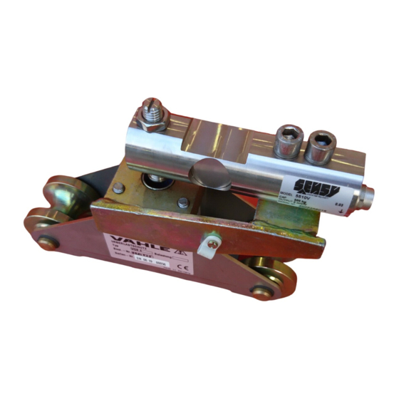
5510 CELL SERIES
INSTALLATION MANUAL
Page 1 on 14
Rev: 27-03-19
Advertisement
Table of Contents

Subscribe to Our Youtube Channel
Summary of Contents for SENSY 5510 Series
-
Page 1: Table Of Contents
5510 CELL SERIES INSTALLATION MANUAL 1. GENERAL INFORMATION .................................2 1.1. Placement at level ..................................2 1.2. Shocks ......................................2 1.3. Electrical weldings ..................................2 1.4. Lightning ......................................3 1.5. Protection hood ...................................3 1.6. Exterior mechanical influences ..............................3 2. ADJUSTEMENT THRUST...................................4 2.1. Setting of anti-reverse .................................4 2.2. -
Page 2: General Information
Rev. Date Reason 27/03/2019 Adding point 4, 5, 6, 7, 8 and 9 (EU Declaration of Conformity) 1. GENERAL INFORMATION 1.1. Placement at level Differences of a few tenths can usually be tolerated with the 5510 bending cell series. Nevertheless, when the differences are greater and when the mounting is higher than three feet, it is important, for correct use, to install shim packs that ensure equal force distribution between them. -
Page 3: Lightning
Stranded ground wire 1.4. Lightning If there is a risk of lightning, it is advised to isolate the cell the best possible and derive the former by stranded wire. In order to do that; place a rubber sheet under the sole and polyamide waterproof washers under the fixing screws. -
Page 4: Adjustement Thrust
2. ADJUSTEMENT THRUST 2.1. Setting of anti-reverse This setting is done when the cell is UNLOADED. Using wrenches, lock the central nuts A&B to the middle of the threaded rod. To turn the stop screw upwards, move nut A. To go down, move nut B. The setting is done when the base plate is in contact with the head of the screw. -
Page 5: Cabling
(preferably screwed connections). It is advised to place a bag of SILICA GEL to keep dry inside the junction box. SENSY could provide PVC junction box with a PG9 packing-gland, which could receive 4 or 6 parallel cells. -
Page 6: Calibration
If there is no fault to be seen, it is necessary to verify the internal circuit. SENSY can help to diagnose on the basis of the associated diagnosis sheet provided in the appendix and filled in beforehand. -
Page 7: Output Impedance
3.7. Output impedance The Wheatstone bridge is made up of 350 Ω gauges. At the output signal (OUT+: green, OUT-: white), the resistance is 350 Ω ± 3 Ω. This impedance must be in accordance with the individual cell data sheet, which can easily be determined with a multimeter. -
Page 8: Use In Potentially Explosive Atmosphere (Option)
2. Make sure that the axle beam has not been knocked (markings) or chemically attacked (some corrosive greases). If points 1 and 2 are not accounted for, just take preventive measures. (annually) 3. In case of doubt, reply to the diagnostic questionnaire available on Web: www.sensy.com/support. 4. Verify the integrity of the cable. -
Page 9: Use Features
The manufacturer’s guarantee is applicable as far as mounting recommendations and general use principle, like above described, are respected. For any particular use, not described in this document, it is mandatory to obtain a prior written agreement from SENSY S.A. for the validity of the guarantee. 8. DRAWINGS AND WIRING DIAGRAMS MA-5510_EN.doc... - Page 10 Ref. Item Capacities Weight (kg) 5510-A 0.5 - 2 t 0.95 Other capacities and dimensions available on request Dimensions in mm Wiring Accessories Load direction...
- Page 11 X-VIEW X-VIEW (SEE ARROW DIRECTION AND CABLE POSITION) Ref. Item* Capacities F5510-A 0.5 - 2 t * Material: stainless steel Other capacities and dimensions available on request Dimensions in mm Other views...
- Page 12 Ref. Item* Capacities Ø1 Weight (kg) I551x-A 0.5 - 2 t 12.5 ±6.76 * x=Material: I5510 - stainless steel; I5515 - alloy steel Other capacities and dimensions available on request Dimensions in mm Other views Electrical ground strap...
- Page 13 R5510-A1 R5510-A2 Range: 500 kg - Weight: 0.097 kg Range: 750 kg - Weight: 0.127 kg Ref. Item* Capacities R5510-A1 500 kg R5510-A2 750 kg - 2 t * Material: R5510 - stainless steel Other capacities and dimensions available on request Dimensions in mm Other views 70.5...
-
Page 14: Eu Declaration Of Conformity
CONCERNED ITEMS: 5510, see calibration certificate related to model and serial number. SENSY S.A. certify that the items described here above have been duly designed, manufactured and tested for use in accordance with the essential requirements defined in the European Directives listed here under.


Need help?
Do you have a question about the 5510 Series and is the answer not in the manual?
Questions and answers