
Related Manuals for Konsberg mPAP 201-C


Summary of Contents for Konsberg mPAP 201-C
- Page 1 µPAP 201-C Portable Acoustic Positioning system Instruction manual 494326/A September 2022 © Kongsberg Maritime AS...
- Page 2 Document information • : Kongsberg µPAP 201-C Product • : Instruction manual Document • : 494326 Document part number • Revision • : 1 September 2022 Date of issue Copyright The information contained in this document remains the sole property of Kongsberg Maritime AS.
-
Page 3: Table Of Contents
Instruction manual Table of contents ABOUT THIS MANUAL .............. 5 INTRODUCTION............... 6 System description ......................7 System diagram........................8 System units ........................9 µPAP 201-C transducers...................9 Responder Driver Unit (optional)................10 Junction box (optional)...................10 APOS - the µPAP 201-C operator system.............. 11 Scope of supply........................ 11 General supply conditions....................12 Receipt, unpacking and storage................12 Equipment responsibility..................12... - Page 4 µPAP 201-C TECHNICAL SPECIFICATIONS..........33 Performance specifications ....................34 Power specifications......................36 Environmental specifications ...................37 Weights and outline dimensions ..................38 DRAWING FILE..............39 Installing the transducer to the ship’s side pole ...............40 µPAP 201-C series outline dimensions................41 Responder Driver Unit dimensions..................42 µPAP 201-C junction box dimensions................43 Fibre to responder drive converter, wiring diagram ............44 494326/A...
-
Page 5: About This Manual
About this manual About this manual This manual includes all necessary documentation to safely install, operate and maintain the system. Target audience This manual is intended for all users of the system. Online information All end-user documentation can be downloaded from our website. https://www.kongsberg.com/maritime/ Registered trademarks Observe the registered trademarks that apply. -
Page 6: Introduction
µPAP 201-C Instruction manual Introduction Topics System description, page 7 System diagram, page 8 System units, page 9 Scope of supply, page 11 General supply conditions, page 12 Support information, page 13 494326/A... -
Page 7: System Description
Introduction System description The product range consists of several models. µPAP is a portable and compact acoustic positioning system for tracking ROVs, tow fish, divers or other subsea objects at several thousand metres range. The system is housed in a compact transducer casing, making it well suited for installation onboard an Uncrewed Surface Vehicle (USV). -
Page 8: System Diagram
µPAP 201-C Instruction manual System diagram The system diagram outlines the standard configuration of a µPAP portable acoustic positioning system and its main units. Only the main connections between the units are included in the diagram. Customer’s computer Customer’s power supply unit Transducer Responder Driver Unit (optional) Ethernet switch (optional) -
Page 9: System Units
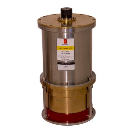
Introduction System units µPAP 201-C transducers The transducer’s casing is made of stainless steel and bronze in order to obtain optimal anti-corrosion properties. The casing encloses and protects the electronics and the acoustic transducer elements needed for transmitting and receiving acoustic signals, as well as the roll and pitch motion sensor and the power supply. -
Page 10: Responder Driver Unit (Optional)
µPAP 201-C Instruction manual Responder Driver Unit (optional) The Responder Driver Unit controls and distributes responder trigger signals to responders. The Responder Driver Unit is a stand-alone unit. The Responder Driver Unit is connected to the transducer. APOS controls and activates the designated drive prior to reception of the sync/timing signal from the transceiver. -
Page 11: Apos - The Μpap 201-C Operator System
Introduction APOS - the µPAP 201-C operator system A µPAP 201-C transducer is operated from an acoustic positioning operator station (APOS). The acoustic positioning operator station, or APOS for short, is a PC running Windows OS with dedicated acoustic positioning software (APOS software). The µPAP 201-C transducer has a built-in PC running Windows OS with an APOS pre-installed. -
Page 12: General Supply Conditions
µPAP 201-C Instruction manual General supply conditions General supply conditions apply to this µPAP 201-C delivery. Receipt, unpacking and storage Upon accepting shipment of the equipment, the shipyard and/or the dealer must ensure that the delivery is complete and inspect each shipping container for evidence of physical damage. -
Page 13: Support Information
Introduction Support information Should you need technical support for your µPAP 201-C system you must contact a Kongsberg Maritime office. A list of all our offices is available on our website. You can also contact our main support office in Norway. Manuals and technical information can be downloaded from our support website. -
Page 14: Installation
µPAP 201-C Instruction manual Installation Topics Installing the transducer, page 15 Installing the Responder Driver Unit (optional), page 16 Converting from fibre optical to electrical signal, page 17 494326/A... -
Page 15: Installing The Transducer
Installation Installing the transducer µPAP is designed for easy installation onboard ships and other surface units. Prerequisites Caution The cabling must be done before installing the transducer. Context The transducer is mounted on the ship’s arrangement for the transducer. This may be on a pole lowered through a moon pool or a hull unit. -
Page 16: Installing The Responder Driver Unit (Optional)
µPAP 201-C Instruction manual Mount the transducer with the forward indicator pointing forward. Fasten the stud bolts. Installing the Responder Driver Unit (optional) The Responder Driver Unit is a stand-alone unit and can be mounted either horizontally or vertically. Prerequisites The unit should be located where it is most suitable for connecting the cables to the responders. -
Page 17: Converting From Fibre Optical To Electrical Signal
Installation Converting from fibre optical to electrical signal The converter works both ways and can be used to create an optical isolation between high voltage equipment and a transceiver. Context You need one kit for each responder signal. Connectors are included to lengthen the cable if needed. -
Page 18: Cabling
µPAP 201-C Instruction manual Cabling Topics Cable plan, page 19 Cable list, page 20 µPAP 201-C pinout, page 21 Connecting the system cables, page 22 494326/A... -
Page 19: Cable Plan
Cabling Cable plan The cables are not part of the delivery with the main units. Customer’s computer Customer’s power supply unit Transducer Responder Driver Unit (optional) Ethernet switch (optional) Junction box (optional) 494326/A... -
Page 20: Cable List
µPAP 201-C Instruction manual Cable list Cables C1-C3 are required to make the system operational. Cables C4-C15 are required if an optional Responder Driver Unit together with an Ethernet Switch are part of the system. An optional special pigtail cable is available upon request. Cable Type From/To... -
Page 21: Μpap 201-C Pinout
Cabling µPAP 201-C pinout This is the pin configuration for a male connector, as seen towards the connector (face view). The connector is a Gisma 10.00.4.19.2.10-Y 19 pin male with keyway 66°. Pin number Signal Ethernet Tx – Ethernet Rx + Ethernet Rx –... -
Page 22: Connecting The System Cables
µPAP 201-C Instruction manual Connecting the system cables All relevant wires in the pigtail cable must be terminated before connecting the system units. Make sure all wire terminations have been performed correctly. Procedure Connect the pigtail cable to the transducer. (C1) Connect the ethernet cable to the pigtail and to the Computer. -
Page 23: Pinout Responder Trigger Signal Cables With D-Sub Connectors
Cabling Pinout responder trigger signal cables with D-sub connectors The responder trigger signal cables connecting the Responder Driver Unit and the responders are not included in the delivery and must be supplied by the installation shipyard. Terminate the responder trigger signal cables as illustrated with D-sub connectors. 494326/A... -
Page 24: Operating Procedures
µPAP 201-C Instruction manual Operating procedures Topics Accessing APOS online help on a µPAP 201-C, page 25 Positioning principles and processing, page 26 494326/A... -
Page 25: Accessing Apos Online Help On A Μpap 201-C
Operating procedures Accessing APOS online help on a µPAP 201-C A µPAP 201-C transducer is operated from an acoustic positioning operator station (APOS). The acoustic positioning operator station, or APOS for short, is a PC running Windows OS with dedicated acoustic positioning software (APOS software). Context The µPAP 201-C transducer has a built-in PC running Windows OS with an APOS pre-installed. -
Page 26: Positioning Principles And Processing
µPAP 201-C Instruction manual Positioning principles and processing µPAP Processing The μPAP system identifies the position of a subsea target, either a transponder or a responder, by directing a reception beam towards the target and measure the heading and range to the target. The target’s position is displayed on the APOS’ display either as a 2D or a 3D position projection of the target relative to the ship. -
Page 27: Maintenance
Maintenance Maintenance Topics Preventive maintenance schedule, page 28 Inspecting and cleaning the transducer, page 29 Creating a backup, page 29 494326/A... -
Page 28: Preventive Maintenance Schedule
µPAP 201-C Instruction manual Preventive maintenance schedule Preventive maintenance must be carried out periodically in order to preserve reliability and ensure safe operation during the system’s service life. The preventive maintenance activity is broken down into specific tasks and the tasks are organized periodically in a preventive maintenance schedule. -
Page 29: Inspecting And Cleaning The Transducer
Maintenance Inspecting and cleaning the transducer The transducer must always be handled correctly in order to preserve its accuracy and prolong its service life. Context A transducer is a delicate precision instrument and must be treated as such. Incorrect handling may damage the transducer beyond repair. Procedure Clean the unit thoroughly with a lot of fresh water. -
Page 30: Spare Parts
µPAP 201-C Instruction manual Spare parts Topics µPAP 201-C spare parts, page 31 Responder driver unit spare part, page 32 Junction box spare part, page 32 494326/A... -
Page 31: Μpap 201-C Spare Parts
Spare parts µPAP 201-C spare parts • µPAP 201-C Part name: • 468079 Part number: • µPAP 201-C-m30 Part name: • 465865 Part number: • µPAP 201-C-X Part name: • 468078 Part number: 494326/A... -
Page 32: Responder Driver Unit Spare Part
µPAP 201-C Instruction manual Responder driver unit spare part • : Responder driver unit spare part Part name • : 321990 Part number The spare part kit consists of: • Responder Driver Unit • AC/DC Power supply • Trigger cable •... -
Page 33: Technical Specifications
Technical specifications Technical specifications Topics Performance specifications, page 34 Power specifications, page 36 Environmental specifications, page 37 Weights and outline dimensions, page 38 494326/A... -
Page 34: Performance Specifications
µPAP 201-C Instruction manual Performance specifications These performance specifications summarize the main functional and operational characteristics of the system. Transducer • 20-30 kHz Frequency: • 4000+ m. Range capability is depending on line of sight, Range capability: transponder's transmit power setting, ship's acoustic system and influence of ambient noise and ray bending. - Page 35 Technical specifications • Angular accuracy: 0.26°/0.45%, range: ±0.02 m • Motion sensor accuracy Roll: 0.01° Pitch: 0.01° Heading: 0.1° Range: ±180° µPAP 201-C-X • Part number: 465078 • Angular accuracy: 0.39°/0.68%, range: ±0.02 m • Motion sensor accuracy Roll: 0.02° Pitch: 0.02°...
-
Page 36: Power Specifications
µPAP 201-C Instruction manual Power specifications These power characteristics summarize the supply power requirements for the system. µPAP 201-C • 24 VDC nominal (18-36 VDC) Voltage requirement: • Max. 75 W, nominal 25 W Power consumption: µPAP 201-C-m30 • 24 VDC nominal (18-36 VDC) Voltage requirement: •... -
Page 37: Environmental Specifications
Technical specifications Environmental specifications These environmental specifications summarize the temperature and humidity specifications for the system. µPAP unit • 0° C to +35° C Operating temperature: • -20 ° C to + 70 ° C Storage temperature: Responder Driver Unit •... -
Page 38: Weights And Outline Dimensions
µPAP 201-C Instruction manual Weights and outline dimensions These weights and outline dimension characteristics summarize the physical properties of the system. µPAP 201-C • 199 mm Diameter: • 404 mm Height: • 16.0 kg Weight: µPAP 201-C-m30 • 199 mm Diameter: •... -
Page 39: Drawing File
Drawing file Drawing file Topics Installing the transducer to the ship’s side pole, page 40 µPAP 201-C series outline dimensions, page 41 Responder Driver Unit dimensions, page 42 µPAP 201-C junction box dimensions, page 43 Fibre to responder drive converter, wiring diagram, page 44 494326/A... -
Page 40: Installing The Transducer To The Ship's Side Pole
µPAP 201-C Instruction manual Installing the transducer to the ship’s side pole This is an example of how to install the µPAP transducer to the pole. 494326/A... -
Page 41: Μpap 201-C Series Outline Dimensions
Drawing file µPAP 201-C series outline dimensions 494326/A... -
Page 42: Responder Driver Unit Dimensions
µPAP 201-C Instruction manual Responder Driver Unit dimensions 494326/A... -
Page 43: Μpap 201-C Junction Box Dimensions
Drawing file µPAP 201-C junction box dimensions 494326/A... -
Page 44: Fibre To Responder Drive Converter, Wiring Diagram
µPAP 201-C Instruction manual Fibre to responder drive converter, wiring diagram 494326/A... - Page 46 µPAP 201-C Instruction manual Index support ............ 13 technical support ......... 13 about how to document downloads ........5 clean the transducer......... 25, 29 online information ........5 create a backup ........... 29 registered trademarks........5 install the RDU........... 16 target audience ..........
- Page 47 Index system diagram..........8 offices............13 plan Support information ........13 cable ............19 system positioning principles and processing....26 diagram............. 8 power system cables requirements ..........36 list ............20 preventive system software maintenance ..........28 backup ............. 29 maintenance schedule ........
- Page 48 ©2022 Kongsberg Maritime...
Need help?
Do you have a question about the mPAP 201-C and is the answer not in the manual?
Questions and answers