Table of Contents
Advertisement
Quick Links
Residual Oxygen / Carbon Dioxide Meter
PACK LEADER
Operation Manual
Thank you for purchasing the PACK LEADER.
The PACK LEADER is an analyzer that samples gas from bags, bottles, cans, etc.,
and measures the residual oxygen concentration (O
and carbon dioxide concentration (CO
This manual describes how to operate the PACK LEADER and the precautions that
must be observed to ensure proper and safe use. Always read this manual and fully
understand the operation before starting use.
Keep this manual near the device for quick reference at any time.
/ RO-105LS
), gas replacement rate (REP),
2
) .
2
With Warranty
Advertisement
Table of Contents

Related Manuals for Iijima PACK LEADER RO-105LS


Summary of Contents for Iijima PACK LEADER RO-105LS
- Page 1 Residual Oxygen / Carbon Dioxide Meter / RO-105LS PACK LEADER Operation Manual With Warranty Thank you for purchasing the PACK LEADER. The PACK LEADER is an analyzer that samples gas from bags, bottles, cans, etc., and measures the residual oxygen concentration (O ), gas replacement rate (REP), and carbon dioxide concentration (CO This manual describes how to operate the PACK LEADER and the precautions that...
- Page 2 Before starting use 1. Safety precautions (Always observe) This section explains the precautions that must be observed to prevent injury to the user or other persons or damage to property. ■ Thefollowingsymbolsclassifyandexplainthedegreeofharmorpropertydamagethatmayresultifthe contents of the symbols are ignored and the product is used improperly. This symbol indicates a dangerous situation that could result in fatal or Warning serious injuries if the information is ignored and the product is handled...
- Page 3 Caution Do not damage the power cord or power Handle the battery correctly. plug. The battery could rupture or ignite if handled incorrectly. If the battery fluid leaks, it could Do not damage, process, place heavy objects corrode the device or contaminate hands or on, heat, place near a source of heat, forcibly clothing.
- Page 4 Oxygen sensor warranty x 1 copy “WAGNIT ” is a registered trademark of the Iijima Electronics Corporation oxygen sensor. ® * Refer to the instructions enclosed with each product for details on handling.
-
Page 5: Precautions For Oxygen Sensor (Model: Wa-Sgf2)
■WA-SGF2warrantyterm When the sensor is already mounted in the main unit, the warranty is valid for one year from the date of shipment from Iijima Electronics Corporation. When purchasing the single sensor unit, the warranty is valid for one year from the date that the sensor package is opened. (Note that the maximum... -
Page 6: Table Of Contents
Contents Before starting use 1. Safety precautions ( Warning, Caution, Note) 2. Confirmation of package contents Package contents, Accessories (options), Accessories (Consumable parts) 3. Precautions for oxygen sensor (Model: WA-SGF2) Names and functions of each part Main unit section • • • • • • • • • • • • • • • • • • • • • • • • • • • • • • • • • • • • • • • • • • • • • • • • • • • • • • • • • • • • • • • • • • 1 Housing section /... -
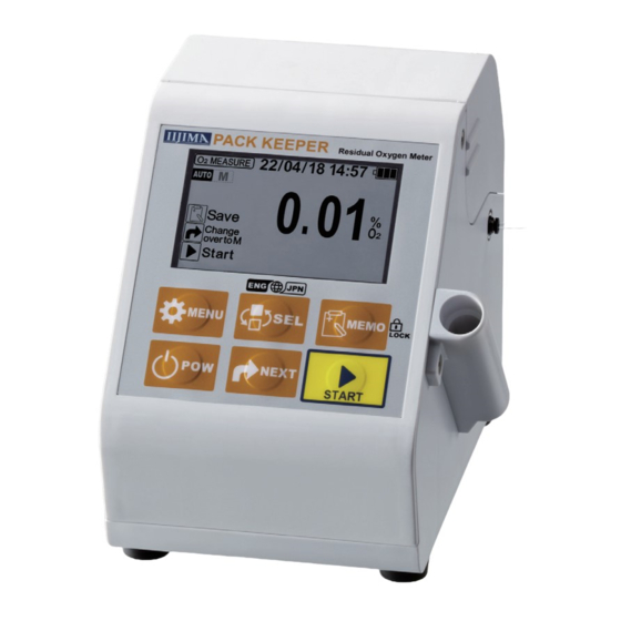
Page 7: Names And Functions Of Each Part
Names and functions of each part Main unit section The correct order and direction for connecting the sampling adaptor are indicated with a sticker. Main cover When operating or storing the unit, refer to this sticker and confirm that the sampling adaptor is correctly connected. -
Page 8: Sensor
Housing section Probe Probe cable Oxygen sensor Housing sensor (already mounted inside) O-ring for Oxygen sensor housing Oxygen sensor (WAGNIT ® (Model: WA-SGF2) Product name O x y g e n S e n s o r WAGNIT ® Model Serial No. M... -
Page 9: Operation Methods
Operation Methods 1. Preparing for use Using the PACK LEADER with batteries The batteries are mounted before shipment, so the PACK LEADER can be used right away. When replacing the batteries, use AA alkaline batteries or nickel-metal hydride batteries (ENELOOP). Using the PACK LEADER with 100 VAC power Always use the enclosed AC adapter. -
Page 10: Switching The Measurement Mode / Automatic Stability Decision Function / Key Lock / Unlock Function
T h e m o d e i s s e t t o A u t o a s t h e d e f a u l t w h e n t h e u n i t i s Switching the measurement mode shipped. -
Page 11: Japanese / English Selection Function
Japaneseisthefactorydefaultsettingforthedisplay.The Japanese/Englishselectionfunction displayedlanguagecanbeswitchedbetweenJapanese and English from any screen. Usually, the language can be switched between Japanese and English from any screen if the power is ON. Note that the language cannot be switched during the following operations. The language can be switched once the operation is fin- ished or canceled and the built-in pump has stopped. -
Page 12: Calibration (O Measurement)
3. Calibration (O measurement) The calibration process adjusts the instrument measured value so that the span point and zero point during O measurement match the sensor output when the reference gases (atmosphere, nitrogen) were measured. Perform span calibration once a day before starting measurements. Ideally, span calibration Span calibration should be performed when the temperature of the oxygen sensor and temperature sensor are sufficiently stable, such as first thing in the morning before operating the air conditioning... -
Page 13: Zero Calibration
To accurately measure low concentrations when measuring O , use nitrogen gas for calibration. Zero calibration Set the needle so it can suction the nitrogen gas. Press The MENU screen opens, and “CAL” is selected (flashes). Press The O CAL screen opens. * If even one measurement has been taken, the previous measured value will display. -
Page 14: Measurement And Recording
4. Measurement and recording Preparing to measure • It may not be possible to measure if the sample gas quantity is less than 10mL. • A measurement can be taken even if the inside of the sample is depressurized, but if the package’s internal pressure is less than -30kPa, a correct measurement value may not be obtained. -
Page 15: O /Co /Co
Measurement (Auto mode) The measurement starts automatically when is pressed. Refer to the section “Switching the measurement mode” (page 4 ) for details on switching between the auto mode and manual mode. When the Measurement Standby screen is displayed, press The measurement starts, and the Stability Decision screen opens. - Page 16 The measured value is not automatically saved in the internal memory. Using the Memory function following steps, up to 300 values can be saved and retained in the internal memory. When 300 values are exceeded, the oldest data is automatically deleted. Press on the Measurement Complete screen.
-
Page 17: Erasing The Measurement History / Guidance Display Function [Procedure Display]
The latest measurement value records can be deleted one item at Erasing the measurement history a time. Use this when a measurement value has been accidentally saved. Hold down for 1 seconds or longer on the HISTORY Screen. “Erase Complete” displays for approx. one second, and then contents of the data saved last are erased from the internal memory. -
Page 18: Various Settings And Functions
Various Settings and Functions The display method can be changed to display the O Setting the O displays [O DISP SET] measurement value as gas replacement rate. However, even if the display is changed to the replacement rate % display, the CO measurement value will not change from the concentration display to the replacement rate display. -
Page 19: Setting The Time [Time Set]
Setting the time [TIME SET] Set the time if the displayed time has deviated. When the Measurement Standby screen is displayed, press The MENU screen opens. Immediately after opening, “CAL” is selected (flashes). Press The cursor moves, and “SET” is selected (flashes). Press The SETTING MENU screen opens. -
Page 20: Time Zone Selection Function [Timezone]
When using the instrument in a country or region Time zone selection function [TIMEZONE] otherthanJapan,theinstrument’sinternalclock can be changed to the local UTC (coordinated universal time). A time zone is a geographical region that uses the same standard time. The deviation from the UTC (coordinated universal time) is expressed with a positive or negative sign, such as “UTC+9:00”. -
Page 21: Output Setting [Out Set]
Complete the settings to use the printer (optional, sold separately) or to use Output setting [OUT SET] a personal computer (prepared by the user) to read the measured values or perform control. (The factory default setting is “No Output”.) When the Measurement Standby screen is displayed, press The MENU screen opens. -
Page 22: Checking For Clogging [Clog Check]
Checking for clogging [CLOG CHECK] If the gas path, such as the needle or tubing, is clogged, the gas cannot be suctioned properly, and correct measurement cannot be made. A clogging check is performed to check for any clogging. The clogging check makes a decision using the pressure sensor that is built into the gas path. If the gas path is not clogged, the pressure will be between 0 and -5kPa. - Page 23 Follow the on-screen instructions and steps below to check for clogging. <Example 1> To check for clogging in the needle (1) Expose the tip of the needle to the atmosphere and press The pump operates for 5 seconds and decides whether there is clogging. Does not change from “-40.3kPa”...
-
Page 24: Initialization [Initialize]
Use this function if the measured value is incorrect after calibration. It resets the Initialization [INITIALIZE] display setting, O calibration value, CO disable setting, upper limit setting, calibration value, measurement mode, and output setting to the factory default settings. The initialization will reset any arbitrary settings to the factory default settings. -
Page 25: Erasing The Entire History [Clr All Hst]
Erasing the entire history [CLR ALL HST] The measurement data saved in the internal memory with the “Memory Function” (refer to page 10 ) can be erased in a batch. Note that the data cannot be redisplayed once it has all been erased. When the Measurement Standby screen is displayed, press The MENU screen opens. -
Page 26: Co 2 Functions And Settings
functions and settings When not measuring the CO , the CO value displayed on the Disabling the CO display [CO OFF] bottom line of the MEASURE screen can be disabled. If the CO disable display setting is set to “ON”, the CO is not measured, and only the O is measured. -
Page 27: Upper Limit Setting [Up Limit Set]
Upper limit setting [UP LIMIT SET] When measuring a sample with a high O concentration and a high CO concentration, the upper limit can be set to 100% so that the total of the O measurement value and CO measurement value does not exceed 100%. When the upper limit is set, the amount exceeding the 100% total is subtracted from the CO value and displayed. - Page 28 Press The CO UP LIMIT screen opens. The currently setting status is selected (flashes). Each time is pressed, the cursor will move between * The display on the left shows the upper limit setting set to “OFF”. Select , and press The upper limit setting complete screen opens, and the setting of the CO disable is completed.
-
Page 29: Co 2 Calibration [Co 2 Cal]
Calibration [CO CAL] If the displayed CO measurement value is abnormal, the deviation can be calibrated with CO calibration. Prepare CO standard gas (15 to 90% CO ) with a random concentration. Set the concentration in the PACK LEADER and calibrate. Ideally, the calibration should be performed when the CO sensor temperature is sufficiently stable in the measurement environment. - Page 30 Press The CO calibration value setting screen opens. * The display on the left shows the state with “+” selected. Set the CO calibration value with the following steps. Press . The cursor will move in the order of When is pressed, the cursor function will activate.
-
Page 31: Connecting To An External Device (Serial Communication)
Connecting to an external device (Serial communication) The measurement data can be printed out by connecting a printer (optional, sold Connecting a printer separately). A printer cable is required to connect the printer. (RS-232C serial cross cable 25-pin male to 9-pin female) Refer to page 15 and set the output setting destination to “PRINTER”. -
Page 32: Maintenance
Maintenance Knurled screws for the Main cover main cover Replacing the oxygen sensor Loosen the knurled screws fixing the main cover on the back of the main unit. Open and remove the main cover. <Back side> Turn the sensor counterclockwise and pull it straight out Sensor Housing of the housing (red). -
Page 33: Replacing The Membrane Filter / Replacing The Check Valve
If liquids enter the membrane filter, the gas path will be clogged, and Replacingthemembranefilter measurement will not be possible. If liquids accidentally get inside, replace the membrane filter to resume measurements. (Note that if the liquid contains oil, it might pass through the membrane filter. Carefully observe the passage state when measuring samples containing oil.) Remove the needle from the membrane filter. -
Page 34: Troubleshooting
Troubleshooting Troubleshooting If you suspect any malfunction or trouble, always perform the following confirmation and remedy before requesting repairs. If the symptoms do not subside, refer to the section “After Sales Service”(page 37) and contact the dealer from which you purchased the product. When inquiring, you may be asked to provide the Displaying the product information product information, which can be displayed with the... - Page 35 If the symptoms do not improve even after taking the above The CO sensor can be replaced only by Iijima Electronics Corporation. actions, the CO sensor may have reached its service life or Contact the dealer from which you purchased the product for replace- may be faulty.
- Page 36 If the symptoms do not improve even after taking the above The CO sensor can be replaced only by Iijima Electronics Corporation. actions, the CO sensor may have reached its service life or Contact the dealer from which you purchased the product for may be faulty.
- Page 37 Make a request for repairs. actions, the main unit or printer may be faulty. Reference: Refer to the Iijima Electronics Corporation website for information on troubleshooting, handling, and maintenance. https://www.iijima-e.co.jp/ Contact the dealer from which you purchased the product if you have any questions or inquiries regarding handling.
-
Page 38: Error Messages
CO calibration. calibration. If the symptoms are not resolved even after The CO sensor can be replaced only by Iijima taking the above actions and confirming Electronics Corporation. Contact the dealer the calibration conditions, the CO sensor... - Page 39 Refer- Symptom Check Action ence page Sensor warranty expired The oxygen sensor cannot be used for more The oxygen sensor can be used past the warranty than one year. term. However, the following “Sensor life reached” error will occur in time, and calibration and This message indicates that the measurements will not be possible.
- Page 40 If the symptoms do not improve even after The CO sensor can be replaced only by Iijima taking the above actions, the CO sensor may Electronics Corporation. Contact the dealer from have reached its service life or may be faulty.
- Page 41 Refer- Symptom Check Action ence page High concentration gas Was a high concentration gas sample just If the sensor is exposed to high concentration gas, the measured? life could be shortened. When halting measurements detected for two minutes or longer, measure the atmosphere This message indicates that high once to lower the concentration.
-
Page 42: Product Specifications
Approx. 620g (including batteries) When measuring multiple samples successively in the Auto mode. • “WAGNIT ® ” is a registered trademark of the Iijima Electronics Corporation oxygen sensor. • These specifications are subject to change without notice for product improvement. -
Page 43: After Sales Service
PACK LEADER: Two years from the date of shipment from Iijima Electronics Corporation Oxygen sensor: One year from the date of the sensor package is opened Note that the maximum warranty term is two years from the date of shipment from Iijima Electronics Cor- poration, including the storage term* and warranty term. - Page 44 1-1, Ishida, Toyooka-cho, Gamagori-shi, Aichi 443-0011 JAPAN Telephone: +81-533-67-2827 Facsimile: +81-533-69-6814 https://www.iijima-e.co.jp/...
Need help?
Do you have a question about the PACK LEADER RO-105LS and is the answer not in the manual?
Questions and answers