
Related Manuals for Acer KG241Q


Summary of Contents for Acer KG241Q
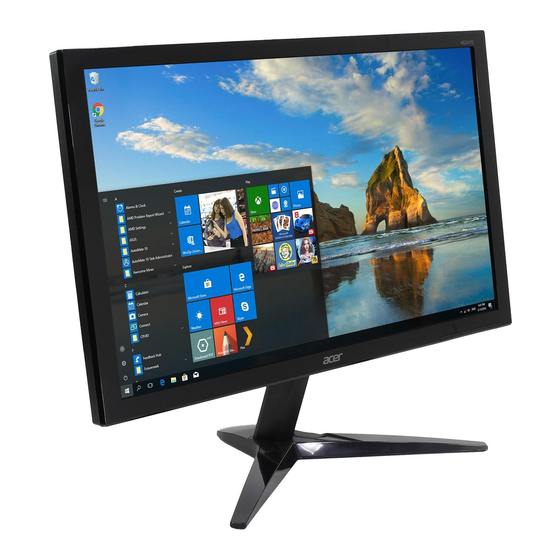
- Page 1 23.6" LCD Monitor ACER KG241Q Service Service Service Acer Monitor KG241Q LIFECYCLE EXTENSION GUIDE...
-
Page 2: Table Of Contents
Contents Important Safety Notice............................ 3 1. Exploded view diagram with list of items ...................... 4 2. Mechanical Instruction ..........................5 3. Firmware Upgrade Process ........................13 4. Writing EDID Process ..........................13 5. FRU (Field Replaceable Unit) List ......................27 6. -
Page 3: Important Safety Notice
Important Safety Notice Proper service and repair is important to the safe, reliable operation of all ACER Company Equipment. The service procedures recommended by ACER and described in this service manual are effective methods of performing service operations. Some of these service operations require the use of tools specially designed for the purpose. -
Page 4: Exploded View Diagram With List Of Items
1. Exploded view diagram with list of items ACER Part Item Description TPV Part No. KEY BOARD KEPCEQBA 55.TA2M2.003 LCD M236HGE-L20 C5 NB IDC 750GBN236GEK52N000 #N/A ADAPTER BOARD PLPCFE321AGE7 55.T2BM2.007 MAIN BOARD-CBPRITMC0Q1 756GQGCB0BA156000Q 55.TA2M2.001 395GLM3030L5790000 CABLE 30P 160MM (MB TO PANEL) -
Page 5: Mechanical Instruction
2. Mechanical Instruction Tools Required List the type and size of the tools that would typically can be used to disassemble the product to a point where components and materials requiring selective treatment can be removed. Tool Description: − Screwdriver (Phillip-head, Hexagonal head) −... - Page 6 2.1 Disassembly Procedures: Remove the stand ASS’Y and unscrew the screw on rear cover. Remove the rear cover. Use a tool (like picture using) to open all latches. (Be careful the position of the key board.) Tear up all tapes and disconnect the LVDS cable (main board to panel), lamp power cable (power board to panel), remove the key board from the bezel.
- Page 7 Separate the panel and the bezel. Take off the mylar and turn over the shield and unscrew the screws on main board and power board. Take off the speakers.
- Page 8 Use a Hex-head screwdriver to tighten the screws and unscrew the screw for locking the connector. Remove the main board and power board. Disconnect the cables.
- Page 9 2.2 Assembly Procedures: Prepare a main board, a power board, a key board and some essential cables. Connect every cable as the below picture. Use a screwdriver to tighten the screws till the power board and main board with shield are firmly attached and paste the mylar on the power board.
- Page 10 Prepare speakers, a mainframe. Assemble the speakers to the mainframe as below picture. Use a Hex-head screwdriver to tighten the screws for locking the connector. Prepare a panel. Put panel into bezel.
- Page 11 Paste the tapes and connect lamp power cable (mainboard to panel, power board to panel). Assemble bezel and key board. Prepare a rear cover to assemble it. Use the screws to lock the rear cover. Assemble the stand-base ass’y to rear cover...
-
Page 13: Firmware Upgrade Process
3. Firmware Upgrade Process 1.Materials list ISP JIG: 715GT089-C VGA cable TPV P/N: 089G728 GAA DB Monitor USB cable TPV P/N: 089G1758 X USB port driver ISP tool: New F/W... - Page 14 2.Connection 3.Install USB driver. 3.1. When insert the USB cable to PC USB port, will pop up a Hardware Wizard to help you install the USB driver if you use this ISP board first time. You can install it successfully as the below instruction step by step. Remark: The USB driver files path: D:\FTC100103(Mstar)\FTCUSB.INF...
- Page 16 After installation the USB serial port driver, please check the port. Look the properties of “my Computer” 4. Install RTD tool. 4.1. double- clicks the icon to run it. Note: Must to install driver firstly...
- Page 17 4.2. Choose the FTDIUSB communication way. 4.3 Click “ISP” and “ISP Option” to set the parameter.
- Page 18 4.4 Close the “ISP Option” window and click the “BigBin” to load the correct F/W. 4.5 Click to start programming.
- Page 19 4.6 After about 20 minutes, there will pop up message as below figure which promotes the upgrade successful. 5. Check the FW version after upgrade. 5.1. The way to open factory menu. (1) Connect VGA source to monitor and turn it on. (2) The way to factory menu: Pressing the left button and DC on, when the screen lights, release the key and press the left botton again to open the menu with “F”...
- Page 20 Check this F/W version. (3)Do “Auto Color” in factory mode. 5.2. Do factory reset in user menu. (1)Restart the monitor after open factory menu. And then open the user menu.
- Page 21 (2)Factory reset will turn off “Burn in” mode which screen color switches among red, green, blue and black.
-
Page 22: Writing Edid Process
4. Writing EDID Process 1.Materials list ISP JIG: 715GT089-C VGA CABLE USB CABLE TPV P/N: 089G728 GAA DB TPV P/N: 089G1758 X MSTAR driver Monitor USB port driver ISP tool EDID... - Page 23 4.1. Change the EDID files name as below rule. VGA EDID WA.dat HDMI EDID WH.dat HDMI2 EDID WH2.dat 4.2. Copy these files to one folder named as Acer KG241Q which must contains “config.ini” file. 4.3. Copy Acer KG241Q to DDC folder and put DDC and ISP tool together.
- Page 24 5. Run the ISP tool 5.1. Double-click the icon to open the tool. 5.2. Select the EDID folder.
- Page 25 Load EDID successful. 5.4 Start to writing. Click “write EDID” to start writing. When The green “PASS” appear, the process is finished.
- Page 26 6. Troubleshooting. 6.1. Can’t write! (1) AC on the monitor and turn on it.(Restart the monitor) (2)Take apart the monitor and connect the 7pin of EEPROM to GND to diable write protection then write EDID one by one. (3) Set the Burn in on last to try again.
-
Page 27: Fru (Field Replaceable Unit) List
5. FRU (Field Replaceable Unit) List This chapter gives you the FRU (Field Replaceable Unit) listing in global configurations of ACER KG241Q Refer to this chapter whenever ordering for parts to repair or for RMA (Return Merchandise Authorization). Please note that WHEN ORDERING FRU P ARTS, you should c heck the most up-to-date information available on your regional web or channel. - Page 28 CABLE 6P 160MM (PB TO 395G801406WJ54 50.LS1M2.005 PANEL) CABLE (MB TO 395G801404LF72 50.T4ZM2.002 SPEAKER) HDMI CABLE 389G0184GAA502 50.LZ2M2.005 1500 D-SUB CABLE 089G-725CAA-2A 50.LNY0B.014 1500 AUDIO CABLE 389G017356G596 50.LXPM2.001 1500 POWER CORD 1500MM BLACK 389G404A15NCXG 27.T2JM2.001 (EUROPE)
- Page 29 BEZEL Q34G8002AEMI3L0130 60.TA2M2.001 REAR COVER Q34G8463AEM03S0100 60.TA2M2.002 STAND HINGE 705GQGCS034312 60.T8VM2.003 ASSY BASE ASSY 705GQGCS034326 60.T8WM2.005 MAINFRAME Q15G2072101Y0100ZA 33.TA2M2.001...
-
Page 30: Trouble Shooting Instructions
6. Trouble shooting instructions...
Need help?
Do you have a question about the KG241Q and is the answer not in the manual?
Questions and answers