
Subscribe to Our Youtube Channel
Related Manuals for Electrolux Professional PD9C


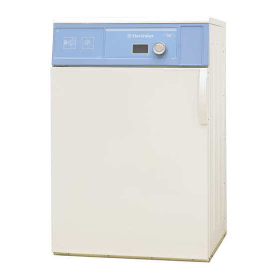
Summary of Contents for Electrolux Professional PD9C
- Page 1 Installation manual Tumble dryer PD9C Type N1190.. 438 9055-00/EN Original instructions 2022.10.06...
-
Page 3: Table Of Contents
Contents Contents 1 Safety Precautions ..........................5 General safety information......................6 Commercial use only........................6 Symbols............................7 2 Warranty terms and exclusions......................8 3 Technical data.............................9 Drawing ............................9 Technical data .........................10 Connections ..........................10 4 Setup ...............................10 Unpacking ..........................10 Siting ............................11 Mechanical installation ......................11 5 Marine installation ..........................12 6 Reversing the door ..........................13 7 Evacuation system ..........................15... -
Page 5: Safety Precautions
Installation manual 1 Safety Precautions • Servicing shall be carried out only by authorized personnel. • Only authorized spare parts, accessories and consumables shall be used. • The machine is not to be used if industrial chemicals have been used for cleaning. •... -
Page 6: General Safety Information
Installation manual • Oil-affected items can ignite spontaneously, especially when exposed to heat sources such as in a tumble dryer. The items become warm, causing an oxidation reaction in the oil. Oxidation creates heat. If the heat cannot escape, the items can become hot enough to catch fire. -
Page 7: Symbols
Installation manual 1.3 Symbols Caution Caution, hot surface Caution, high voltage Read the instructions before using the machine... -
Page 8: Warranty Terms And Exclusions
Warranty will be applicable where the customer has used only genuine spare parts and has performed maintenance in accordance with Electrolux Professional user and maintenance documentation made available in paper or elec- tronic format. Electrolux Professional strongly recommends using Electrolux Professional approved cleaning, rinse and descaling agents to obtain optimal results and maintain product efficiency over time. -
Page 9: Technical Data
Installation manual 3 Technical data 3.1 Drawing B(a) B(b) Operating panel Door opening, ⌀ 400 mm Electrical connection Exhaust connection B(a) B(b) 1114... -
Page 10: Technical Data
Installation manual 3.2 Technical data Weight, net Drum volume litres Drum diameter Drum depth Drum speed Rated capacity, filling factor 1:18 (Max. load) 10.6 Rated capacity, filling factor 1:22 (Recommended. load) Heating: Electricity Air consumption, Electric heating, 6 kW Air consumption, Electric heating, 8 kW Pressure drop, Electric heating, 6 kW Max. -
Page 11: Siting
Installation manual 4.2 Siting The machine should be positioned so that there is plenty of room for working, both for the user and service personnel. The figure shows minimum distance to a wall and/or other machines. 10 mm / 10 mm / 400 mm / 3/8 inch 3/8 inch... -
Page 12: Marine Installation
Installation manual 5 Marine installation To ensure steadiness of the machine it is important to fasten the machine to the foundation. Fasten the four fittings (supplied with the marine machine model) to the foundation using four x M10 set screws. If the four fittings are not supplied, order kit No. -
Page 13: Reversing The Door
Installation manual 6 Reversing the door Disconnect the power to the machine. Demount the hinge (A) and refit the screws into the same holes in order to secure the panel on the back. Mount the hinge (A) at the bottom of the opposite side. Demount the door by carefully lifting it of the front. - Page 14 Installation manual Demount the door handle and remount the screws. Mount the door handle on the opposite side using the existing scews. Mount the door by lifting it back on the fitting on the opposite side. Mount the hinge (B) at the top. fig.7658 Demount the magnetic door lock (E) and magnet for switch (F) and mount on the opposite side.
-
Page 15: Evacuation System
Installation manual 7 Evacuation system 7.1 Air principle The fan creates low pressure in the machine, drawing air into the drum via the heating unit. The heated air passes through the garments and the drum vents. The air then flows out through a lint filter positioned in the door. After this, the air is evacuated through the fan and ex- haust system. -
Page 16: Shared Exhaust Duct
Installation manual 7.4 Shared exhaust duct It is recommended that each machine is connected to a separate exhaust duct. When several machines shall use the same exhaust duct the exhaust duct must increase after each machine. The recommended diameter increase progression is the one in the table. If several machines are installed on the same exhaust pipe, it is recommended to adjust the airflow on the machines when all machines are started and running a program with no heat. -
Page 17: Electrical Connection
Installation manual Diagram with pressure drop curve The grey area marks the recommended working area. Check that the pressure drop is within the recommended working area. 6 kW 8 kW Y = Pa Y = Pa x = m3/h x = m3/h 8 Electrical connection 8.1 Electrical installation The electrical installation may only be carried out by qualified personnel. -
Page 18: Single-Phase Connection
Installation manual 8.2 Single-phase connection Demount the cover panel from the supply unit. Connect the earth and other wires as shown. 1NAC 1NAC When the installation is completed remount the cover panel and check: • That the drum is empty. •... -
Page 19: Electrical Connections
Installation manual 8.4 Electrical connections Heating alternative Main voltage Heating power Total power Recommended fuse Electric heated 220–240V 1 ~ 50/60 6.0/8.0 6.3/8.3 35/50 220–230V 3 ~ 50/60 6.0/8.0 6.3/8.3 20/25 240V 3 ~ 50/60 6.0/8.0 6.3/8.3 16/25 380–415V 3 ~ 50/60 6.0/8.0 6.3/8.3... -
Page 20: At First Power Up
Installation manual 9 At first power up When the installation is complete and the power is connected for the first time you will be forced to make the following settings. When one setting is ready you will automatically enter the next one. •... -
Page 21: Function Check
Installation manual 10 Function check May only be carried out by qualified personnel. A function check must be made when the installation is finished and before the machine can be ready to be used. Whenever a repair has been made, a function check must be performed before the machine can be used again. Check the automatic stop of the machine •... -
Page 22: Disposal Information
Installation manual 11 Disposal information 11.1 Disposal of appliance at end of life Before disposing of the machine, make sure to carefully check its physical condition, and in particular any parts of the structure that can give or break during scrapping. The machine’s parts must be disposed of in a differentiated way, according to their different characteristics (e.g. - Page 24 Electrolux Professional AB 341 80 Ljungby, Sweden www.electroluxprofessional.com...
Need help?
Do you have a question about the PD9C and is the answer not in the manual?
Questions and answers