Table of Contents
Advertisement
Advertisement
Table of Contents

Related Manuals for AC Infinity AIRPLATE Series

Summary of Contents for AC Infinity AIRPLATE Series
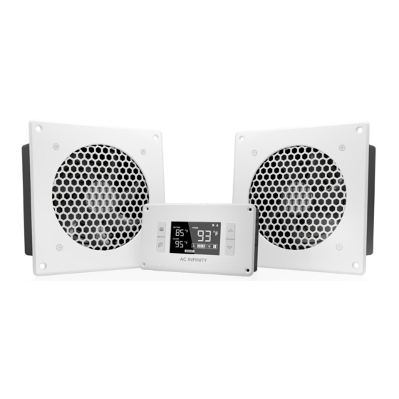
- Page 1 AIRPLATE SERIES CABINET COOLING SYSTEM USER MANUAL...
- Page 3 WELCOME Thank you for choosing AC Infinity. We are committed to product quality and friendly customer service. If you have any questions or suggestions, please don’t hesitate to contact us. Visit www.acinfinity.com and click contact for our contact information. EMAIL LOCATION support@acinfinity.com...
- Page 4 MANUAL CODE CF2207X1 PRODUCT MODEL UPC-A AIRPLATE S1 AI-CFS80BA 854759004044 AIRPLATE S2 AI-APS2 854759004723 AIRPLATE S3 AI-CFS120BA 854759004006 AIRPLATE S5 AI-CFD80BA 854759004105 AIRPLATE S7 AI-CFD120BA 854759004068 AIRPLATE S9 AI-APS9 854759004549 AIRPLATE P7 AI-APP7 819137022812 AIRPLATE T3 AI-APT3 854759004372 AIRPLATE T7 AI-APT7 854759004389 AIRPLATE T8...
-
Page 5: Manual Index
Powering Other Devices ..............Page 19 Programming: S-Series ..............Page 20 Programming: T-Series ..............Page 21 Programming: P-Series ..............Page 27 Multi-Zone Controller ..............Page 29 Frequently Asked Questions ............Page 30 AC Infinity Products ............... Page 31 Warranty ..................Page 32... -
Page 6: Product Warning
PRODUCT WARNING TO REDUCE THE RISK OF FIRE, ELECTRIC SHOCK, OR INJURY TO PERSONS, OBSERVE THE FOLLOWING: Ensure your power source conforms to the electrical requirements of this product. Check your local code restrictions for additional safety measures that may be needed for a proper code compliant installation. - Page 7 CABINET COOLING GUIDE INTAKE AND EXHAUST All cabinet fan systems should contain an intake and an exhaust variable, which can either be fans or ventilation holes. This is required to balance the static pressures between the inside and outside of the cabinet. FAN POSITIONING Due to natural convection, warmer air which is less dense than colder air will rise on its own.
-
Page 8: Key Features
SMART energy mode. and CNC machined corners. AC INFINITY DUAL BALL BEARINGS THERMAL PROBE FAN EXPANSION PORTS Fans contain long-life ball The corded sensor probe Each fan unit contains an USB bearings rated at 67,000 hours. - Page 9 KEY FEATURES P-SERIES EFFICIENT MOTOR THERMALLY ACTIVATED SLEEK FRONT PLATE PWM-controlled motor Programmed with four speed Features an aluminum frame featuring precise speed settings and thermal triggering to with a brushed black finish and control, low noise operation, turn on the fans upon reaching CNC-machined edges for a and energy efficient DC power.
-
Page 10: Product Contents
S-SERIES CABINET PLASTIC MOUNTING USB POWER FAN UNIT STENCIL SCREW SET ADAPTER (x1) (x1) (x4) (x1) T-SERIES (Includes S-SERIES Fan Units) AC INFINITY THERMAL THERMAL PLASTIC MOUNTING AC POWER CONTROLLER PROBE STENCIL SCREW SET ADAPTER (x1) (x1) (x1) (x4) (x1) - Page 11 CHANGING FAN DIRECTION STEP 1 Unplug the cabinet fan before flipping the internal fan. Remove the screws using a Phillips screwdriver to separate the front plate and the internal fan from the shell. STEP 2 Identify the airflow direction to achieve your desired configuration;...
- Page 12 CHANGING FAN DIRECTION STEP 3 Lift the fan guard to run the cord through one of the open grooves, then guide the fan into the shell. Reapply the screws to secure the fan, fan guard, and shell together. STEP 4 Replace the grille and front plate over the open side.
- Page 13 MOUNTING STEP 1 Determine your desired mounting location. Place and secure the stencil over it using tape and mark the drilling points and outline. STEP 2 Drill the mounting holes into your wall space. Cut the rectangular outline to create the opening.
- Page 14 MOUNTING STEP 3 S-Series Push the cabinet fan into the cut opening to create a flush mount, making sure the fan's backside does not touch its perimeter to minimize vibration noise. P-Series...
- Page 15 MOUNTING STEP 4 S-Series Screw the bolts into the mounting holes to secure the cabinet fan. P-Series...
- Page 16 POWERING S/T-SERIES S-SERIES Power the cabinet fan by plugging the USB connector into either a USB port or into the included power adapter, to then plug into an outlet. T-SERIES Plug the cabinet fan’s USB connector into one of the multi-zone controller’s USB ports. Plug the power adapter’s male connector into the multi-zone controller’s power port, then plug the two-pronged end into an outlet.
- Page 17 POWERING P-SERIES STEP 1 Plug the AC power cord into the 3-pin port, located on the backside of the cabinet fan. STEP 2 Plug the AC power cord into a wall outlet to power the cabinet fan.
- Page 18 (AIRPLATE S7 contains two fans and AIRPLATE S9 contains three fans). Fan units connected with the thermal controller will share the same speed and temperature settings. If the fans contain an inline speed controller, set their speeds to HIGH. AC INFINITY AC INFINITY...
-
Page 19: Powering Other Devices
POWERING OTHER DEVICES P-SERIES STEP 1 You may use the two rear USB ports to power up to two USB devices (supports up to 5V per port). These devices are powered on and off using the switch on the front side. STEP 2 You may use the four rear outlet sockets as you would a power strip to power up to four... -
Page 20: Speed Controller
PROGRAMMING S-SERIES SPEED CONTROLLER Sets the fan speed to OFF, LOW, MEDIUM, or HIGH. Daisy-chained fans will also adjust to this setting. All systems with more than four daisy-chained fans must set their inline speed controller to HIGH to prevent overloading this speed controller (ex. - Page 21 PROGRAMMING T-SERIES 1. MODE BUTTON 2. UP / DOWN BUTTON 3. LEAF BUTTON Cycles through the unit’s modes: Adjusts the value of the setting Shuts off the display while AUTO, SMART, OFF, ON, and alarm temperatures, allowing programs to run. ALARM.
-
Page 22: Quick Start
PROGRAMMING T-SERIES QUICK START Navigate to the AUTO Mode using the MODE button. Use the up and down buttons to adjust the SETTING temperature. The PROBE temperature displays the thermal probe’s current measurement. When the PROBE temperature meets or exceeds the SETTING temperature, the fans will start running. -
Page 23: Off Mode
PROGRAMMING T-SERIES OFF MODE PROBE SETTING Your fan will not run while in this mode. Use the up and down buttons to adjust the backlight brightness. Setting the brightness to the auto-dim level (1st ALARM and 3rd bars illuminated) will dim the display to the lowest setting whenever the controller is not being used after 30 seconds. -
Page 24: Alarm Setting
PROGRAMMING T-SERIES ALARM SETTING PROBE SETTING Sets a temperature alarm that will trigger when the PROBE temperature meets or exceeds the ALARM temperature. Use the up and down buttons to adjust the ALARM temperature. ALARM Leave the ALARM Mode after adjusting its setting for it to be active. -
Page 25: Controller Lock
PROGRAMMING T-SERIES VARIATION BUFFER Adjusts the gap from your SETTING temperature to prevent the fans from shutting off too quickly due to fluctuating change in the environment. This setting toggles between 4°F (2°C) and 2°F (1°C) buffers. Hold the MODE button and DOWN button together for 3 seconds to change the variation buffer to 2°F (1°C). -
Page 26: Alert Icons
PROGRAMMING T-SERIES ALERT ICONS Two alert icons are displayed at the top right corner of the screen. These icons denote which system function is being monitored. Icons may flash when the controller signals an alert to notify you of any triggered function. PROBE SETTING ALARM... -
Page 27: Powering On/Off
PROGRAMMING P-SERIES SPEED MODE POWERING ON/OFF Flip the switch to turn on or turn off the rear outlets and USB ports. This switch will control the power of additional devices plugged into the cabinet fan. FAN SPEED ADJUSTING Press the button to adjust the cabinet fan's speed level from 0-4. -
Page 28: Trigger Setting
PROGRAMMING P-SERIES THERMAL MODE THERMAL ADJUSTMENT 4 || 96° Hold the button until the indicator light changes 3 || 92° to orange to switch to Thermal Mode. 2 || 88° This button will only control the cabinet fan, and will not control any additional devices plugged 1 || 84°... - Page 29 ALARM FANS POWER LABEL AC INFINITY OTHER SETTING DIFFERENCES Hold the ZONE button to set the display to Fahrenheit or Celsius. Hold the MODE button to lock or unlock the display. Hold ZONE and MODE buttons to turn the display off while programs run.
- Page 30 AIRPLATE FAQ Can I mount this cabinet fan vertically? Yes. The AIRPLATE can be mounted in any orientation, including vertically. How do I flip the fan to create intake or exhaust airflow? Unplug the fan unit to power it off. Unscrew the bolts from the frontplate and the body, then flip the fans within the body and screw the bolts back in.
- Page 31 AC INFINITY PRODUCTS Component USB Fans The MULTIFAN series fans can be placed on top of AV components and electronics to economically exhaust hot air. It features an inline speed controller and can be powered by a USB port. The fans can also be powered through a power outlet with a boost speed adapter (sold separately).
-
Page 32: Warranty
WARRANTY This warranty program is our commitment to you, the product sold by AC Infinity will be free from defects in manufacturing for a period of two years from the date of purchase. If a product is found to have a defect in material or workmanship, we will take the appropriate actions defined in this warranty to resolve any issues. - Page 33 No part of the materials including graphics or logos available in this booklet may be copied, photocopied, reproduced, translated or reduced to any electronic medium or machine readable form, in whole or in part, without specific permission from AC Infinity Inc.
- Page 36 www.acinfinity.com...
Need help?
Do you have a question about the AIRPLATE Series and is the answer not in the manual?
Questions and answers