Advertisement
Quick Links
ADMX-512
512 Channel DMX/RDM Controller
Please read through this manual thoroughly before use, any damage
caused by misuse of product will not be covered by warranty.
A powerful 512 channel DMX/RDM controller with 32 fixtures. Each fixture controls up to 32 channels per
unit. There are 32 storable scenes and 32 storable chases, each with up to 100 steps which can be
triggered manually, by sound or automatically using the time faders between 0.1 seconds and 10 minutes.
An integrated USB port provides back up of up to 16 banks of DMX settings, scenes and chases on an
attached USB storage device. The hardwearing metal chassis can be used standalone or 3U rackmount if
preferred and the detachable carry handle makes the unit easy to move from event to event.
In the box:
Your ADMX-512 should arrive with you in a single carton in good condition. The carton should contain
1 x main unit, 1 x UK power adaptor and 1 x user guide.
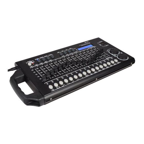
Controls Overview:
17.
18.
3.
1.
2.
www.avsl.com
5.
11. 12. 13. 14.
4.
6. 7.
Item ref: 154.105UK
User Manual
15.
154.105UK User Manual
16.
10.
8.
9.
Advertisement

Related Manuals for Qtx ADMX-512


Summary of Contents for Qtx ADMX-512
- Page 1 In the box: Your ADMX-512 should arrive with you in a single carton in good condition. The carton should contain 1 x main unit, 1 x UK power adaptor and 1 x user guide.
- Page 2 1. Channel faders 1-16: For adjusting the DMX values of the connected light effect units. The current DMX value is indicated in the display. Controls 1-4 also adjust the brightness ratio of the red, green, blue and white LEDs of the connected light effect units and control 5 adjusts the total brightness. 2.
-
Page 3: Operation
17. Power input: Insert the jack plug of the supplied PSU. 18. Power on/off switch: Switches the controller on and off. Setting up: 1. Connect the power supply to the socket on the side of the unit and plug into a mains socket. 2. - Page 4 •For optimum results of the color effects triggered by buttons 15 and 16, the operation with a least 8 devices is recommended. 4. The parameters of the movement patterns and color effects can be edited and adapted to your application. •Movement patterns 1-9: Press the SWAP button to switch between the parameters and adjust the values with the Pan/Tilt wheels.
- Page 5 Calling Illumination Scenes: Static scenes from the memory bank can only be used in manual mode. 1. There should be no device selected. If one of the control LEDs of the number buttons 1- 16 is lit, press the corresponding button to deselect. 2.
- Page 6 •The display indicates the number of the control channel in the lower line and the current output value as a DMX value. 7. It is also possible to call a scene previously memorized or a movement pattern or color effect and insert it into the chase.
- Page 7 5. A flashing LED indicates which chase can be adjusted when several chases are selected simultaneously. The chase selected last can be adjusted. To adjust a different chase instead, keep the corresponding number button pressed until its LED flashes. 6 To stop a chase, press the corresponding number button so that its LED goes out. Adjusting Fade-in for the Color Channels: It is possible to adjust a fade in time for chases affecting the RGBW color channels 1-4 and the dimmer channel.
- Page 8 Configuration and System Settings Manual Assignment of DMX Starting Addresses: It is possible to individually assign the DMX starting addresses to the controller. The assignment can be made in the system settings. 1. Switch on the controller with the rear power switch. The unit is in manual mode and the display indicates “Manual”...
- Page 9 8. Press the DEL button to delete an assignment (indication "NULL“). •To confirm the deleting procedure, all LEDs of the controller flash three times. 9. After your settings, exit the system settings. For this, keep the MENU button pressed for 2 seconds. Inverting Output Values: It is possible to individually invert the output values of the 512 control channels.
-
Page 10: System Setting
pan wheel). Press the ENTER button to begin with the configuration. The display indicates “PLEASE SELECT FIXTURE”. 3 Keep the number button pressed of the unit to be copied. 4 In addition, press the number button you would like to copy the values to. The display shortly indicates “COPY“. - Page 11 RDM DMX Address setup [RDM DMX address assignments]: This menu allows identifying connected RDM devices and changing their DMX address assignment. 1. Keep the MENU button pressed for 2 seconds to call the system settings. 2. Call the menu item "05.RDM DMX Address setup" with the pan wheel and confirm with ENTER. 3.
-
Page 12: Specifications
3. Call the menu item "07. Data load" with the pan wheel and confirm with ENTER. •The display indicates “Press number key Select file“ (select relevant file with number button). •The control LED of a number button lights up, when data is available on the USB memory device for this memory bank.
Need help?
Do you have a question about the ADMX-512 and is the answer not in the manual?
Questions and answers