Table of Contents
Advertisement
Quick Links
Chipsmall Limited consists of a professional team with an average of over 10 year of expertise in the distribution
of electronic components. Based in Hongkong, we have already established firm and mutual-benefit business
relationships with customers from,Europe,America and south Asia,supplying obsolete and hard-to-find components
to meet their specific needs.
With the principle of "Quality Parts,Customers Priority,Honest Operation,and Considerate Service",our business
mainly focus on the distribution of electronic components. Line cards we deal with include
Microchip,ALPS,ROHM,Xilinx,Pulse,ON,Everlight and Freescale. Main products comprise
IC,Modules,Potentiometer,IC Socket,Relay,Connector.Our parts cover such applications as commercial,industrial,
and automotives areas.
We are looking forward to setting up business relationship with you and hope to provide you with the best service
and solution. Let us make a better world for our industry!
Contact us
Tel: +86-755-8981 8866 Fax: +86-755-8427 6832
Email & Skype: info@chipsmall.com Web: www.chipsmall.com
Address: A1208, Overseas Decoration Building, #122 Zhenhua RD., Futian, Shenzhen, China
Advertisement
Table of Contents

Related Manuals for VTI SCP1000

Summary of Contents for VTI SCP1000
- Page 1 Chipsmall Limited consists of a professional team with an average of over 10 year of expertise in the distribution of electronic components. Based in Hongkong, we have already established firm and mutual-benefit business relationships with customers from,Europe,America and south Asia,supplying obsolete and hard-to-find components to meet their specific needs.
- Page 2 Doc.Nr. 8268000.03 SCP1000 DEMO KIT User Manual...
-
Page 3: Table Of Contents
SCP1000 DEMO KIT User Manual TABLE OF CONTENTS 1 Introduction .........................3 2 Quick start for using the SCP1000 DEMO KIT ..............3 3 Hardware..........................4 4 GUI software ........................5 GUI software displays .......................7 4.1.1 USB serial port selection .......................7 4.1.2 Start up and Reset demo ......................7 4.1.3... -
Page 4: Introduction
• Exit the GUI software before unplugging the DEMO KIT from PC (button in upper right corner of the GUI) • After GUI software is stopped, the DEMO KIT can be unplugged from the PC (the SCP1000 DEMO KIT uses virtual serial COM port driver, so it can not be found as a USB device). -
Page 5: Hardware
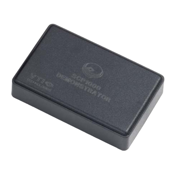
User Manual Hardware The SCP1000 DEMO KIT USB interface board and SCP1000 PCB are shown in Figure 1. The USB interface card converts the USB interface to SPI or TWI interface. The SCP1000 pressure sensor is soldered on chip carrier PCB which is connected to interface board with board to board connectors. -
Page 6: Gui Software
SCP1000 DEMO KIT User Manual GUI software SCP1000 DEMO KIT is controlled via USB serial port by GUI software. The software must be installed into location that is suggested during installation procedure. Screen capture of the GUI is presented in Figure 3. - Page 7 SCP1000 DEMO KIT User Manual The SCP1000 GUI software flow chart is presented in Figure 4 below. Start the GUI sw Back to Meas results display MCU: - resets the SCP1000 - detects the sensor type - detects the serial bus...
-
Page 8: Gui Software Displays
SCP1000 internal EEPROM. SCP1000 also initialised during the start up screen. The MCU software version as well as SCP1000 sensor type is displayed in text field. Figure 6. Start up screen. VTI Technologies Oy 7/19 www.vti.fi Doc.Nr. 8268000.03... -
Page 9: Meas Results
(see Figure 3 and Table 1). The "Trig measurement" button is displayed in the extension part of the window only when the SCP1000 is in low power measurement mode. The Table 5 information 4.1.4 Register config... -
Page 10: Pres Offset Adjustment
Read the current SCP1000 offset adjustment data from the two EEPROM registers ("Read current adjustment data" button) Reset the SCP1000 offset adjustment data by writing zeros in to two EEPROM registers ("Zero offset adjustment data" button) Please refer to the following documents: "TN48 SCP1000 Pressure Offset Adjustment"... -
Page 11: Setup
SCP1000 DEMO KIT is used without the GUI software, see further details from section 5. In this example the SCP1000 DEMO KIT uses COM4 serial port. Standard window frames can be enabled / disabled. In Figure 10 the window frames are disabled. -
Page 12: Using The Scp1000 Demo Without The Gui Software
4. Open the pre-configured Windows HyperTerminal software from the DEMO KIT CD-ROM: SCP1000_Demo_pre-configured_HyperTerminal_connection.ht 5. Type ' * ' (asterisk character), the SCP1000 DEMO KIT sends an info text to HyperTerminal (see Figure 11). If the HyperTerminal software is unable to connect the SCP1000 DEMO... -
Page 13: Communication Commands
After the HyperTerminal connection to SCP1000 USB demo is established, user can communicate with the SCP1000 in side the USB demo according to the communication flow chart presented in Figure 12 below. The register listing is presented in Table 5, see SCP1000 datasheet for further information. - Page 14 Set MCU software to measurement mode selection mode Commands that are used to read/write the SCP1000 registers and to control the SCP1000 are listed in Table 4 below. The register address and data is always in hex format unless otherwise noted.
-
Page 15: Using Two Scp1000 Demo Kits Simultaneously
"Copy of SCP1000-USB-DEMO-VER.2.5.exe". When both demo kits are connected to one PC, the SCP1000 data can be logged to separate files as instructed in section 4.1.3. If the both demo kits are used for data logging purposes, the data can be synchronized with the time stamp in the result file (time is from the PC's system clock). -
Page 16: Usb Interface Board Circuit Diagram
SCP1000 DEMO KIT User Manual USB interface board circuit diagram SCP1000 demo USB interface board circuit diagram is presented in following pages. Figure 13. SCP1000 DEMO KIT USB interface board circuit diagram (sheet USB). VTI Technologies Oy 15/19 www.vti.fi Doc.Nr. 8268000.03... - Page 17 SCP1000 DEMO KIT User Manual Figure 14. SCP1000 DEMO KIT USB interface board circuit diagram (sheet MCU). VTI Technologies Oy 16/19 www.vti.fi Doc.Nr. 8268000.03 Rev.0.03...
-
Page 18: Usb Interface Board Pcb Layout
SCP1000 DEMO KIT USB interface board PCB layout and silkscreen is presented below. Figure 15. SCP1000 demo USB interface board PCB layout (left, top / right, bottom ). Figure 16. SCP1000 demo USB interface board silkscreen (left, top / right, bottom ). -
Page 19: Troubleshooting
DELL laptops (Latitude D600, D610, D410) and desktop PCs with Win2000 and WinXP operating system. If the SCP1000 DEMO KIT does not work properly or it’s operation is limited, the following items may help to sort the problems out: •... -
Page 20: Document Revision History
Change Description 0.01 30.08.2006 First release for GUI version 2.4, Document "TN49 SCP1000 register access with USB-demo" is included in to this document 0.02 08.09.2006 GUI software updated to version 2.5 (user can select the used units in 'Meas results' display) 0.03...
Need help?
Do you have a question about the SCP1000 and is the answer not in the manual?
Questions and answers