
Related Manuals for VTI K85-13.0 Series

Summary of Contents for VTI K85-13.0 Series
- Page 1 Manual of Instruction VTI Quick Release Valve Series K85-13.0/K85-50.0 For transportable and stationary fire fighting installations VTI© 2009 Rev.6 page 1 / 8...
- Page 2 The information in this document is literary property of VTI Ventil Technik GmbH. VTI Ventil Technik GmbH keeps all rights to this document reserved including all copies or partial copies of it produced by customers.
- Page 3 4. VTI Ventil Technik GmbH does in no way assume liability for damages, which can result from improper or misunderstood use of this operation manual. 5. Rights and duties of VTI Ventil Technik GmbH and of the customers / users of this operation manual are defined exclusively by the "General Terms and Conditions"...
- Page 4 The test pressure of the valves for the mentioned inert gases is 240 bar. The test pressure of valves for CO2 is depending on the mounted bursting device, it is max. 250 bar. VTI© 2009 Rev.6 page 4 / 8...
- Page 5 Screw the valves into approved steel cylinders with a torque of: 160 to 180 Nm into 25E acc. to EN 629-1 160 to 180 Nm into 1“ – 11 ½“ NGT 3.2 Mounting Instruction for dip tubes VTI© 2009 Rev.6 page 5 / 8...
- Page 6 6) Leakage test in closed position, as shown in pic. "A" (e.g. by means of a leakage detection spray). 7) Screw on a closing nut (is not necessarily included in the delivery of valves) VTI© 2009 Rev.6 page 6 / 8...
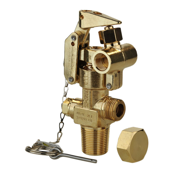
- Page 7 Charge the pneumatic release device with pressure. Effect the release by the operation centre or by external pressure. setting-screw stick-on lever Release cylinder internal thread G 3/8“ (2x) transport safety device closing nut VTI© 2009 Rev.6 page 7 / 8...
- Page 8 2) Screw the housing (pos.2) into the mounting hole of the valve body until it blocks 3) Tighten the screw connection with a torque of 30 – 35 Nm 4) Mount indication disc (pos. 3) VTI© 2009 Rev.6 page 8 / 8...
Need help?
Do you have a question about the K85-13.0 Series and is the answer not in the manual?
Questions and answers