Table of Contents
Advertisement
This manual contains information necessary for the safe and proper use of the PuraLev
specifications for the standard configurations of the pump system and instructions regarding its use, installation,
operation, adjustment, inspection and maintenance. For special configurations of the pump system refer to
accompanying information. If the system must be configured for other parameter settings, then the Levitronix
Software version V2.0.5.0 or higher (with according manual Levitronix
yourself with the contents of the manual to ensure the safe and effective use of this product. After reading this
manual, please store the manual where the personnel responsible for operating the pump system can readily refer to
it at any time.
PL-4034-00, Rev02, DCO# 20-144
®
PuraLev
4.3 bar
140 liters/min
USER MANUAL
User Manual for PuraLev
2000SU
(62.4 psi)
(37 gallons/min)
Doc.# PL-4046-00) is necessary. Familiarize
®
2000SU
www.levitronix.com
®
2000SU. Included are
®
Service
First Release: 20-Apr-2012
Last Update: 09-Jul-2020
Advertisement
Table of Contents

Subscribe to Our Youtube Channel
Related Manuals for Levitronix PuraLev 2000SU

Summary of Contents for Levitronix PuraLev 2000SU
- Page 1 For special configurations of the pump system refer to ® accompanying information. If the system must be configured for other parameter settings, then the Levitronix Service ...
-
Page 2: Table Of Contents
Assembly into Circuit ............................37 TROUBLESHOOTING ............................. 38 Troubleshooting for Operation with Controller LPC-2000.1 ................38 Troubleshooting for Operation with Controller LPC-2000.2 ................38 ® Troubleshooting with Levitronix Service Software ..................38 TECHNICAL SUPPORT ............................38 APPENDIX ................................39 Regulatory Status ............................39 Symbols and Signal Words .......................... -
Page 3: Safety Precautions
Installation shall be done by qualified personnel only. Following safety precautions and all “CAUTION”, “WARNING” and “DANGER” indications in the relevant sections shall be followed. CAUTION ® Do not under any circumstances open the controller or motor. Levitronix does not assume responsibility for any damage, which occurs under such circumstances. CAUTION High magnetic field strength of pump impeller. -
Page 4: Specifications
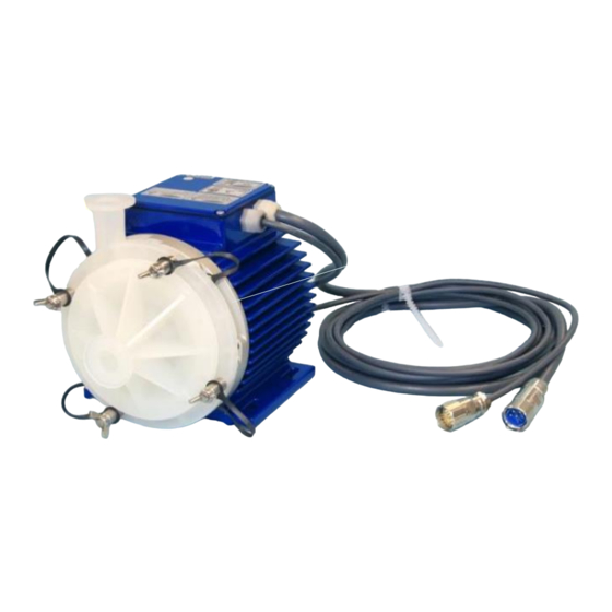
® User Manual for PuraLev 2000SU www.levitronix.com 2 Specifications 2.1 Specification of Components Figure 1 shows the main system components (motor, controllers, and pump head) and Figure 2 illustrates the accessories. Figure 1: Pump system with standard components Figure 2: Pump System Accessories... - Page 5 ® User Manual for PuraLev 2000SU www.levitronix.com System Name Article # Pump Head Motor Controller Note Socket PLD-2000SU.1 100-90726 LPM-2000.7 LPC-2000.1-04 Adaptor/Extension (0.5 - 10m) cables according to Table 3 (Position 4a and 4b) have to be ordered as separate article with specified length.
-
Page 6: Standard System Configurations
A ® USB interface allows communication with a PC in connection with the Levitronix Service Software. Hence parameterization, firmware updates and failure analysis are possible. -
Page 7: General Environmental Conditions
Transient over-voltages typically present on Surge immunity according to EN 61000-4-5 the mains supply Pollution degree Table 5: Environmental conditions for pump system ® Note 1: Contact Levitronix technical department (see Section 7) for outdoor usage. PL-4034-00, Rev02, DCO# 20-144... -
Page 8: Pressure-Flow Curves
® User Manual for PuraLev 2000SU www.levitronix.com 2.4 Pressure-Flow Curves [gpm] Specific gravity = 1 g/cm Viscosity = 0.7 cP Liquid Temp.: 40 C 8000 rpm 7000 rpm [bar] [psi] 6000 rpm 5000 rpm 4000 rpm [lpm] Figure 6: Pressure/flow curves for aqueous liquids (Measured with pump-head DCP-2000.2) -
Page 9: Maximum Static Pressure For Pump Heads
® User Manual for PuraLev 2000SU www.levitronix.com 2.6 Maximum Static Pressure for Pump Heads [°F] Burst pressure at ambient temperature = 25 C is >15 bar after gamma radiation of 40 kGy and 2 times temperature cycling between -25 C and +75 C. -
Page 10: Basic Dimensions Of Main Components
® User Manual for PuraLev 2000SU www.levitronix.com 2.7 Basic Dimensions of Main Components Outlet Triclamp 1“ ASME BPE-2009 ID = 22.1mm Manual Screws (M8) 4pcs M8x25mm Inox A4 (for socket fixation) Inlet Triclamp 1“ ASME BPE-2009 ID = 22.1mm Figure 9: Basic dimensions (in mm and [inch]) of motor LPM-2000.x with pump head DCP-2000.2... - Page 11 ® User Manual for PuraLev 2000SU www.levitronix.com Air Connection Port: NPT ¼“ with max. depth = 14mm Figure 10: Basic dimensions (in mm and [inch]) Motor LPM-2000 with Air Cooling Module ACM-4.2 (Same basic dimenions for ACM-4.3) Cable Cable OD...
-
Page 12: Engineering Information
® User Manual for PuraLev 2000SU www.levitronix.com 3 Engineering Information 3.1 Material and Sealing Concept Figure 12: Sealing and material concept of motor with pump head (Motors LPM-2000.x with pump head DCP-2000.2 and Pump Head Socket PHS-2000.2) Item System Materials... -
Page 13: Ac Supply And Power Consumption
® User Manual for PuraLev 2000SU www.levitronix.com 3.2 AC Supply and Power Consumption 3.2.1 Power Consumption [gpm] 2000 Specific gravity = 1 g/cm 8000 rpm Viscosity = ~ 0.7 cP Liquid Temp.: 40 C 1600 7000 rpm 1200 [Watts] 6000 rpm... -
Page 14: Temperature Monitoring
® User Manual for PuraLev 2000SU www.levitronix.com Situation t Value in [A Peak Value in [A] Switch-on after complete discharge of controller (> 60 s). 29.3 For this case inrush current limiter in the controller are active. Switch-on after in-complete discharge (< 60 s, worst case) 350.8... -
Page 15: Thermal Management
® User Manual for PuraLev 2000SU www.levitronix.com 3.4 Thermal Management 3.4.1 Motor Temperature The motor temperature depends on the ambient and liquid temperature, as well as on the hydraulic operation point and the characteristics (viscosity and density) of the liquid. Figure 16 illustrates the temperature characteristics for aqueous liquids at room temperature. - Page 16 ® User Manual for PuraLev 2000SU www.levitronix.com [gpm] Absolute Temperature Limit 8000 rpm Ambient Temp = 25 C Liquid Temp. = 60 C Specific gravity = 1 g/cm Viscosity = 0.7 cP Recommended Operational Limit Air cooling with ACM-4.2 7000 rpm [°F]...
- Page 17 ® User Manual for PuraLev 2000SU www.levitronix.com The above curves are measurements of the motor temperature at certain liquid and ambient temperatures. Equation (Eq. 1) shows how to approximately extimate the motor temperature for other liquid and ambient temperatures based on these curves.
- Page 18 ® User Manual for PuraLev 2000SU www.levitronix.com 3.4.2 Controller Temperature Depending on the ambient temperature and the placement of the controller additional cooling may be required (see Figure 20). To improve cooling of the controller, place the device into a moving air stream. If the controller is mounted in a compact area or adjacent to additional heat sources (e.g.
-
Page 19: Hydraulic Circuit Design
Figure 21: Avoidance of stress forces and torques at the inlet and outlet of the pump head ® Contact the Levitronix Technical Service department (see Section 7) for more detailed considerations and support on the design of the hydraulic circuit. -
Page 20: Installation
® User Manual for PuraLev 2000SU www.levitronix.com 4 Installation 4.1 Electrical Installation of Controller 4.1.1 Overview The LPC-2000 controllers have signal processor controlled power converters with switched inverters for the drive and the bearing windings of the motor. The signal processor allows precise control of pump speed and impeller position. - Page 21 User Manual for BPS-2000 www.levitronix.com Figure 23: Overview of the controller LPC-2000.2 for extended operation Interface (as labeled) Description Position, field and temperature sensor signals from motor. “SENSORIC” Torque spec. for tightening of connector screws on motor side: Min. = 0.4 Nm, Max. = 0.6 Nm - Analog current input: 4 –...
- Page 22 ® User Manual for PuraLev 2000SU www.levitronix.com 4.1.2 General Installation Instructions WARNING Hazardous voltage may be present. Always isolate the electrical power supply before making or changing connections to the unit. To remove the power it is recommended to use an isolating device.
- Page 23 ® User Manual for PuraLev 2000SU www.levitronix.com 4.1.3 Electrical Installation of Controller LPC-2000.1 for Standalone Operation For standalone operation the LPC-2000.1 is disabled when power is turned on. It can be enabled manually by using the “UP” button on the display. If the controller shall be enabled automatically, when power is applied the “ENABLE”...
- Page 24 ® User Manual for PuraLev 2000SU www.levitronix.com 4.1.5 Installation of PLC Interface for Extended Controller LPC-2000.2 To operate the pump system with a PLC, a minimum set of two digital inputs and one analog input is needed. The digital and analog outputs can be used to monitor the pump status and operating parameters.
- Page 25 Table 14: Signals of the PLC connector for standard firmware Note 1: For other configurations of PLC inputs and outputs refer to alternate firmware documentation. ® Note 2: Configurations can be done with Levitronix Service Software. Note 3: All ground wires have to be connected.
-
Page 26: Mechanical Installation Of The Motor
® User Manual for PuraLev 2000SU www.levitronix.com 4.2 Mechanical Installation of the Motor 4.2.1 Standard Installation Instructions and Information WARNING Overheating of the Motor Power and Extension Power Cable To prevent an overheating of the motor power and extension power cables, do not roll-up or install several motor power cables in the same cable channel. - Page 27 ® User Manual for PuraLev 2000SU www.levitronix.com 4.2.2 Installation of ATEX / IECEx Motors WARNING Motors for ATEX / IECEx and Hazardous Location Cl1 Div2 applications. Only specific types of motors LPM-2000 are classified for the use in Ex classified locations. Refer to the corresponding section in the manual.
-
Page 28: Mechanical Installation Of The Controller
If explosive flammable gases are present, place the controller in an explosion-proof cabinet. CAUTION ® Do not under any circumstances open the controller. Levitronix does not assume responsibility for any damage, which occurs under such circumstances. PL-4034-00, Rev02, DCO# 20-144... -
Page 29: Mechanical Installation Of Adaptor/Extension Cables
® User Manual for PuraLev 2000SU www.levitronix.com 4.4 Mechanical Installation of Adaptor/Extension Cables For connecting the motor to the controller the adaptor cables MCAP-2000.x (for power cable) and MCAS- 600.x (for sensor cable) shall be used (see Table 3 for adaptor cables). For the cables which use an M23 threaded metallic Hummel connector type, check the connection according to the following pictures: ... -
Page 30: System Operation With Lpc-2000.1 (Stand-Alone Version)
® User Manual for PuraLev 2000SU www.levitronix.com 4.5 System Operation with LPC-2000.1 (Stand-Alone Version) 4.5.1 State Diagram of LPC-2000.1 The controller LPC-2000.1 allows stand-alone operation with manual speed setting (“Button Control Mode”) as well as extended operation with analog speed setting (Analog Control Mode). Figure 34 shows the state diagram which can be controlled with the manual buttons and the signals on the “USER INTERFACE”... - Page 31 ® User Manual for PuraLev 2000SU www.levitronix.com 4.5.2 Standalone Operation (Button Control Mode) ▪ When applying power the system defaults into the “Button Control Mode” and goes into the status “OFF ButtonControl” according to Figure 34. Levitation is disabled and the display indicates “OF”.
- Page 32 ® User Manual for PuraLev 2000SU www.levitronix.com 4.5.3 Extended Operation (“Analog Control Mode”) ▪ In order to be able to control the pump with external signals (PLC) the mode “Analog Control Mode” has to be set with the display buttons. The “UP” and “Down” buttons have to be pressed simultaneously during 5 seconds.
-
Page 33: System Operation With Controller Lpc-2000.2 (Plc Version)
® User Manual for PuraLev 2000SU www.levitronix.com 4.6 System Operation with Controller LPC-2000.2 (PLC version) 4.6.1 State Diagram of the PLC Interface Power On Enable: not active Reset: active Status : not active State 1 Priming: on Enable: active Reset: not active... - Page 34 2000SU www.levitronix.com State “Off”: ® The pump system is switched off and the motor has no power. In this state, Levitronix Service Software has full control. State “ON” (speed control mode): The pump system is switched ON and the impeller is rotating with the referenced speed. The motor has electrical power when in this state.
-
Page 35: System Operation For Atex / Iecex Applications
® User Manual for PuraLev 2000SU www.levitronix.com 4.7 System Operation for ATEX / IECEx Applications Specific precautions may be considered while using the pump system in potential explosive gas atmospheres according to ATEX / IECEx category 3G/3D. The pump head of the pump systems must be filled completely with liquid at all time during operation to avoid the occurrence of combustible atmospheres inside the pump casing. -
Page 36: Instructions For Use Of Pump Head
CAUTION The pump head should be inspected prior to use for any damage. Do not use the pump head if any ® damage is found. Contact Levitronix regarding return of any suspected pump head. Gamma Sterilization The pump heads DCP-2000 have been tested to be 5.1.3 Traceability for Troubleshooting... -
Page 37: Mounting Of Pump Head
® User Manual for PuraLev 2000SU www.levitronix.com Mounting of Pump Head 5.3.3 Mounting Step 2: Manual Screw Fixation Align the pump head holes with the threads of the 5.3.1 Preparation pump head socket. Hand tighten the 4 screws. After removal of the pump head from its 5.3.4 Mounting Step 3: Ready-to-Use Check... -
Page 38: Troubleshooting
USB interface. The software can be used for performing detailed troubleshooting. Note: the Levitronix Service Software can not be used with the standalone controller LPC-2000.1. 7 Technical Support For troubleshooting, support and detailed technical information contact Levitronix Technical Service Department: Levitronix Technical Service Department Technoparkstr. -
Page 39: Appendix
® User Manual for PuraLev 2000SU www.levitronix.com 8 Appendix 8.1 Regulatory Status 8.1.1 CE Marking ® The Centrifugal Pump System PuraLev 2000SU, in its various configurations, is in conformity with the below mentioned European Directives. The pump system is thought to be used in hydraulic circuits of production equipment of the Semiconductor, Chemical and general machinery applications. - Page 40 8.1.6 Immunity to Voltage Sags – Semi F47 ® Based on internally testing at Levitronix the pump system PuraLev® 2000SU in its various configurations is able to handle all the voltage sags defined in SEMI F47. Therefore the pump system full fills the requirements of the SEMI F47 standard.
- Page 41 ® User Manual for PuraLev 2000SU www.levitronix.com 8.1.7 Biocompatibility We declare that the wet materials of the DCP-2000.x pump heads, in the configurations as listed below, satisfy the following biocompatibility specifications: Part Name Impeller Material Housing Material Triclamp Gasket DCP-2000.2...
-
Page 42: Symbols And Signal Words
® User Manual for PuraLev 2000SU www.levitronix.com 8.2 Symbols and Signal Words Symbol / Description Type Source Signal Word Indication of an imminently hazardous situation that, if DANGER not avoided, will result in death or severe injury. Signal word SEMI S1-0701...
Need help?
Do you have a question about the PuraLev 2000SU and is the answer not in the manual?
Questions and answers